


| Previous Blog |
|---|
| Project R.A.G. - Blog #7 - The Mainframe - P1 |
Blog #8 - Mechanical Build P2 - Robot On Rails
1. Introduction
Hi! This will be my eighth blog for the 1 Meter of Pi - Design Challenge. I'll begin by wishing everyone a happy new year! In the last blog I went over the first half of the build on the main box which will enclose our Raspberry and some additional electronics. If you are interested in that blog it will be linked at the top and at the bottom of this blog. In this blog I will continue with some work that I started in blog 6 and also do some maintenance on our astronaut which I think will go good with the theme of this blog.
This is the part 2 of the mechanical build, I covered the first part in my sixth blog which you can check out here: Project R.A.G. - Blog #6 - Mechanical Build P1 - Robot On Rails
2. Plan for this blog
In the first part of this blog we had a bit of a situation which can be described with a single picture:
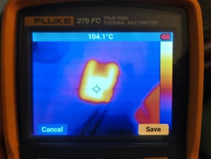
In this blog I will go over why I think this happened and how I fixed the problem (it is working currently, but we will see what will happen with it long term). I've made another change to the system which is the motor which I will also cover here. Besides that, as I've mentioned above, our astronaut needs some work on the motor adapter plate side. This won't be a long blog with a lot of design work, but mostly fixing up stuff and getting them good to go for the finishing of this project. I'll begin by tackling the rail system first.
3. Rail system
To begin with this, let's see where we were last time that we left off, here is a short video test that shows the cart inching forward very slowly with a lot of strange noise as pointed out by dubbie on my last blog where I talked about this.
Shortly after this filming this video, I mounted the robot arm onto its box hooked it up to power, made sure it ran as it should and then trying to connect the motor to the driver only to have nothing happen. I though it was weird at first, but, since I was driving this off of my lab bench power supply where I put the limit on 2A, I could see it was drawing 2A at like 2V or less, every time I tried connecting the driver to power. After playing around a bit with it, I noticed that that happened as soon as I would connect the reset and sleep pins to 5V which turns on the driver, in other words, dead.
Problems from last time
First thing I did when this happened was order new drivers and a new motor to be safe. There are 2 important things to notice in the sentence and that is the plural form of drivers and the new motor, which proved both to be essential. I ordered another DRV8825 but I ordered an additional A4988 driver just in case. Let's begin by talking about what I did in the meantime while waiting for these drivers and motor to arrive. I did some reading trying to understand what went wrong or what I could have messed up. Which gets us into our first troubleshooting and important first step when playing with stepper drivers which is setting the Vref voltage.
Setting the Vref
This is an easy but a really crucial and important step for using these drivers. What is Vref? Vref is the voltage that we can adjust with a tiny screw potentiometer on the stepper driver which gives the driver a current limit for that motor. Adjusting this potentiometer we can limit the max amount of current that goes through the driver.

You can see the small potentiometer on the right side of this picture. To measure the Vref, you need to connect one of the probes to ground and another probe to the screw of the potentiometer itself. An easy way to do this, as suggested on many websites, is to use small alligator clips attached to the screwdriver so you can see the value change as you're turning the screw. Now, to know to what value to set the Vref depends solely on your motor and driver. There is usually a simple formula to follow, for example, for my new motor and DRV8825, the formula is: Current Limit = Vref x 2, and my motor is good up to 1.7A, which means I can set the Vref to no more than 0.85V. For other drivers there is a different formula. Here are guides that cover both the DRV8825 and the A4988:
- https://www.makerguides.com/drv8825-stepper-motor-driver-arduino-tutorial/
- https://www.makerguides.com/a4988-stepper-motor-driver-arduino-tutorial/
Thinking that was it I attached my new motor with it's new long cables and started playing with it and it worked! I mounted than that to the rail system and tried using it there to see it move as it should, for a little while that is... The motor started vibrating again (this time I used the 12V power supply which I made in the last blog and not the lab bench power supply, so I didn't know what kind of current I was drawing) and we have another toasted driver... While checking if the Vref was set correctly is really important, that obviously wasn't the whole thing, there was something more. I will get into that now.
Protecting the driver
One thing that I wasn't adding every time when I played with this circuit was a big cap at the power leads and more thing I shouldn't have done was move the motor by hand specially when using the DRV8825. This sentence sums up pretty much everything that was the problem last time, even more so, this time because I have used really long wires. Initially, I thought the DRV8825 was a better option than the A4988, since it can do 1/32 microstepping and some other stuff, but there is one crucial thing that the A4988 has that the DRV8825 doesn't have. Looking online and at the datasheets it became apparent that the A4988 has 40V Zenner on the inside for protecting the driver while the DRV8825 doesn't. Why is this important? Here is a screenshot from one of those sites linked above:

And this here is the reason for the dying DRV8825 drivers. This is essential on the A4998 which already has more protection, so it's even more important on the DRV8825. To protect the A4988 properly I looked around and found some old caps I desoldered from some PCB-s and put them to good use, another thing I did to further protect the driver was add a 12.1V Zenner. The A4988 has a 40V Zenner as I've already mentioned, but since I am not planning on using that high of voltage, I added the diode as well. This is how the end schematic for me turned out.
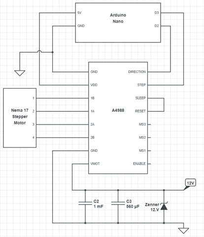
With this, we are almost ready to conduct our first tests with this setup. Besides this, all we needed was a bit of code to test everything out properly. I went to one of the above linked tutorials which covered the A4988 and pasted and modified the code from there. The code that I ended up with looks like this:
#define dirPin 2
#define stepPin 3
#define stepsPerRevolution 200


void setup() {
  // Declare pins as output:
  pinMode(stepPin, OUTPUT);
  pinMode(dirPin, OUTPUT);
}


void loop() {


  digitalWrite(dirPin, HIGH);


  // Spin the stepper motor 5 revolutions fast:
  for (int i = 0; i < 5 * stepsPerRevolution; i++) {
    // These four lines result in 1 step:
    digitalWrite(stepPin, HIGH);
    delayMicroseconds(1000);
    digitalWrite(stepPin, LOW);
    delayMicroseconds(1000);
  }


  delay(1000);


  // Set the spinning direction counterclockwise:
  digitalWrite(dirPin, LOW);


  //Spin the stepper motor 5 revolutions fast:
  for (int i = 0; i < 5 * stepsPerRevolution; i++) {
    // These four lines result in 1 step:
    digitalWrite(stepPin, HIGH);
    delayMicroseconds(1000);
    digitalWrite(stepPin, LOW);
    delayMicroseconds(1000);
  }


  delay(1000);
}
This code was made by using the code from here ( https://www.makerguides.com/a4988-stepper-motor-driver-arduino-tutorial/ ). I modified the code to only spin the motor 5 rotations in one direction and 5 rotations in the other direction. Here is a small test video after uploading this to the Arduino and hooking up the motor and power supply.
As you can see and hear from this video (or better said not hear) this is working so much better now. I've playing around with it quite a bit and was checking the temperatures on the driver but everything seemed great. The only thing I avoid doing as much as I can is rotating to the motor myself by hand. To finish up this part of the blog, all that's left to do is mount the motor to the rails and give it a spin!
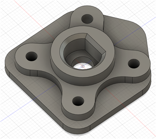
New mount for the motor
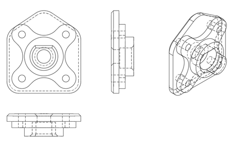
In the last blog for the mechanical build: Project R.A.G. - Blog #6 - Mechanical Build P1 - Robot On Rails . I showed how I designed 2 different mounts for that motor, one for a flat surface mount and the other for mounting it to the 20x20 extrusions. Now it's time to design the third mount since this motor is a bit different. It's roughly the same size with the exact hole spacing of 31mm, but the motor shaft is center while on the other motor it was moved to the side a bit. It was a quick redesign, but a needed one nevertheless. To design the motor mount I used Fusion 360 and printed it on my Ender 3 Pro using Creality white PLA filament. It was printed at standard quality with 205C on the nozzle, 60C on the bed, at 0.2mm layer height using a 0.4mm nozzle. You can find both the STP file and the STL file for this mount on the following link: Rail System 3D models. It will be under name of Nema17 motor mount.
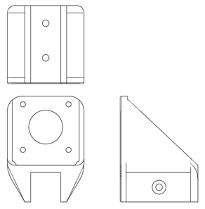
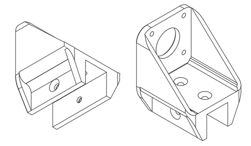
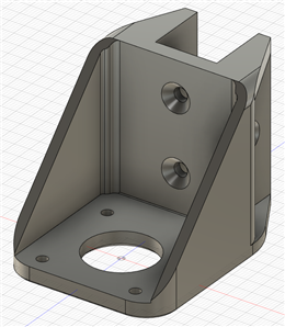
As I've already said, it was almost the same design as the last one, with slightly thicker motor mounting plate and slightly thinner walls to accommodate the slightly wider motor. The only thing left to do is mount this to the rail system and mount the motor so we can finally see if the rail system is working as intended.
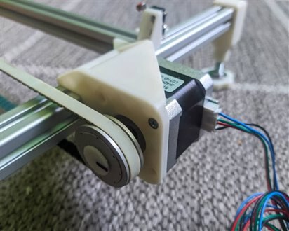
Testing the rail system
Now for the fun part, looking at it move. Here are 2 videos showing the system working, and I'm really happy with how it looks! You can maybe notice that the belt is a bit too lose on the video, I just found through testing that it's functioning much better like that, rather than having the belt too tight. It didn't move as smoothly and also increased the noise. The first test was done with a 1000us delay between the steps, while the second test was done with a 750us delay. I tried 500us also, but it didn't work well.
I am really happy with how it turned out! I've been running it a lot and playing around with it with no issues whatsoever. To recap the things that were wrong and that should be looked at when making a system like this. Calibrate the Vref on your driver according to the rated current of your motor. You can find how to do calculate the Vref for every driver online and can also probably find the motor ratings as well. Capacitors are a must, and without them, the drivers just die, adding a Zenner diode that is closer to your input voltage than 40V won't hurt at all. And lastly, if you can, try avoiding moving the stepper by hand while it's connected to the driver. I'm considering this part completely sorted out now, so it's time to look at our astronaut.
4. Robot surgery
Now it's time to perform surgery on our astronaut. As we have seen before he is a man of many talents, from dancing to art, but even though he is a sporty type, he doesn't handle falls or sudden moves good. The robot arm uses servo motors for moving the joints around. They are a great choice since it makes the arm fairly cheap to make an easy to use, since there are no needed additional motor drivers and so on, the only thing you need to do is send a PWM signal to the data pin of the motor and it will turn from 0 to 180 degrees. The biggest problem however comes in their mechanical design in my opinion.
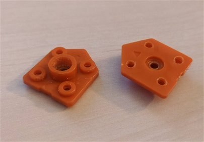
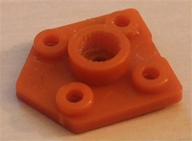
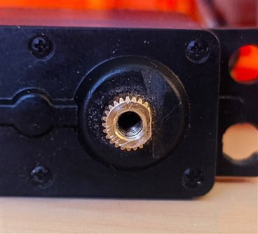
The only problems I ever had with this arm are because of the way the motors are attached to the arm itself. On stepper motors, like the ones I used in this blog earlier, we have what's called a D shaft. It's a thick metal shaft with a flat spot on one side, this gives an ability to transfer great amount of torque easily. On the servo motors however there is a different solution. These motors are usually small and are used for things where a lot of torque is not needed and this problem is obvious when we are using plastic parts. Let's begin by examining the servo motor end.
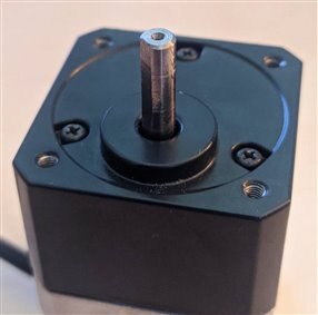
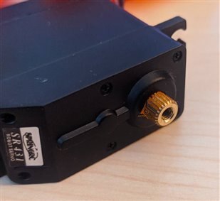
On the first picture you can see the stepper motor and what I talked about. This is a great and reliable way for mounting stuff to the motor, all we need is a mount with the right hole size and shape and a set screw if we want to keep it in place. On the second picture we have the servo motor. You can see that it has small teeth on the outside which are supposed to meat with the teeth on the motor adapter. But here is where we run into the problem. It's good that the teeth on the motor are out of metal, but unfortunately, the motor adapter isn't, it's out of plastic. You can see in the second picture how much orange plastic is stuck between the teeth of the gear from grinding one against the other. To the engineers credit who designed the robot arm, they were aware that this was going to be an issue and made it so you can replace these plates when they fail like they did on me and they even included spares in the box with the robot. Unfortunately, as I've been using this robot for quite a while, I've gone through all of those that were included.
They sell a kit on the store with a spare motor and more of those adapter, but I don't have time to wait for a new set of those, so I need a different solution. This will probably void the warranty (like I haven't done that already with this arm...) but I am going to try and file down a side of this metal gear to make it into a shape of a D shaft and then mimic the shape and holes from the original adapter just with the fitting for the D shaft.
This was surprisingly easy to do with a small hand held file. I thought it would give off a bit more resistance but it went pretty fast. I could have went more, I could have even gone to the thread itself but I thought to stop here and to see if it was good enough. The next thing I had to do was design a small motor adapter to replace the old ones, but, this one had to have the D shape hole in the top. I just used a pair of calipers to get the dimensions and slowly built it up in Fusion but adjusted it so I can print it easily and added a bit more material to be stronger than the original one.
I moved the servo to roughly the 90 degree position because we are losing symmetry by doing this and can't mount the adapter however we want. This just made the modelling process easier knowing that the straight edged part should be at the top as you will see now.
The best thing about it how short the print was at around just 13 minutes. I printed it at 0.2mm layer height, 6 outside walls and 100% infill to make it as strong as possible since it is a small part with only one purpose and that is to transfer torque. If you maybe had the same issue as me and would like to go this way, here is the folder where you can find the 3D model for this part under the name ServoAdapterPlate, you will find both STL and STP files inside: BRACCIO 3D models. All that was left now was to fit this part to our servo.

The adapter fit was spot on! I could have maybe went with a little bit of a smaller diameter on the outer hall but it was already a really tight fit when I was mounting the adapter. The outside dimensions could maybe be trimmed about 0.1-0.2mm to just fit the robot better, but it works great like this as well. I am happy to say that this was the first try for this. The only thing left to do is to see if everything is working on that joint as it should.
That's a relief, the surgery was 100% successful and it promises even more torque ability. As you can see from the video, the range is great and I tried going as fast as I could on the servo with sudden changes to the movement, but nothing gave up. Even if this goes overtime I can just print out more in a matter of minutes, but if I see that it's becoming a recurring problem again, I'll file it down more and redesign the adapter.
5. Testing the motion system
With both systems mended and at 100% I can finally do a test where both of them are doing it's thing. The robot box moving up & down the rails while on top the robot is practicing fencing/art/some other of his many many hobbies. Here's a video of the whole motion system finally working at once!
It works!!! If you're wondering why the robot is moving so slow, in the blog where I covered that build you could see the robot moving really fast, I coded it a bit differently in a way that, when it gets a set of angles that it need to go to, rather than just sending those commands to the servos, I would send current position +/- 1 degree depending on the direction and do that in a loop for all of the servos at once. This way, we don't have the sharp fast movements but rather these much nicer ones but slower. Though, speed is something that can easily adjusted by playing with the size of the step, since now, it's only one degree, and playing with the delay between the 2 steps. I will keep it like this for now, as it gives me the smoothest motion.
6. What's next?
With just a few days remaining there's a fair amount of work left to do, but not impossible. From the hardware standpoint, I need to finish up the construction that will hold the LED-s and modules and make one more module which will be coming soon. The thing that worries me the most is how much I'll be able to do software vise, since that will be the main thing which will connect all of the modules and everything I've done so far into one working project. The next blog will be linked below as soon as I post it!
7. Fun news from the ISS
For this segment of fun news from the ISS, some actual news! The second harvest of radishes was completed by the crew on the ISS. A lot of the harvested plants were documented and taken pictures off and packaged up to be analyzed back on Earth. Some samples were sanitized for consumption by the crew!
8. Summary
This was a shorter blog with not a lot of new design elements, but it was essential never the less. Without getting these 2 things working as they should, the project just wouldn't work as these are the main active components for this project. I am off to the races with finishing up the last module so I can finally play around with the software and finish the project. All of the relevant links for this competition, link to the next and previous blog as well as my GitHub where I'm uploading all of the models can be found underneath. Thanks for reading the blog, hope you liked it and found it interesting!
Milos
Relevant links for the competition:
Link to my GitHub where you can find all of the files used for this project (code, 3D models,...):
Link to my Project Collection:
| Previous Blog | Next Blog |
|---|---|
| Project R.A.G. - Blog #7 - The Mainframe - P1 | Project R.A.G. - Blog #9 - Water & Rail Module |
Top Comments