The emWin is an embedded graphic library and graphical user interface (GUI) framework developed by SEGGER Microcontroller. It provides an efficient, processor- and display- controller-independent GUI for any application that operates with a graphical display and touch including home appliances, automotive, IoT, and industrial. It is compatible with single-task and multi-task environments. Infineon has licensed the emWin library from SEGGER and offers it for free to its customers.
EmWin is a nice tool for displaying bitmap image files which is a main requirement for my project. Using the library in a ModusToolbox project is not a tough job. I was able to use it successfully by doing some research on two example projects (one, two) and the official user guide of emWin.
First I added the emWin library to my project from the Library Manager. (see the image below)

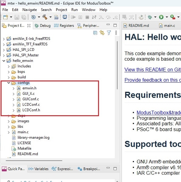
After adding the library I created a sub-directory named as config under the project root directory. I intended to put all emWin related configuration files within this directory to keep those separate from the application files. Before emWin can be used on a target system, the software needs to be configured. Configuring means modifying the configuration files which usually reside in the (sub)directory Configs. The configuration is not very tough, there are some configuration routines which need to be modified in order for the system to work properly with the specific display and environment. According to the documentation of the emWin the following items need to be configured:
- Memory area to be used by emWin
- Display driver to be used for drawing operations
- Color conversion routines to be used
- Display controller initialization
- Hardware acceleration
- Hardware JPEG decoding
The configuration is basically divided into two parts: GUI-configuration and LCD-configuration and all the configuration files can be easily downloaded from Infineon official example project.
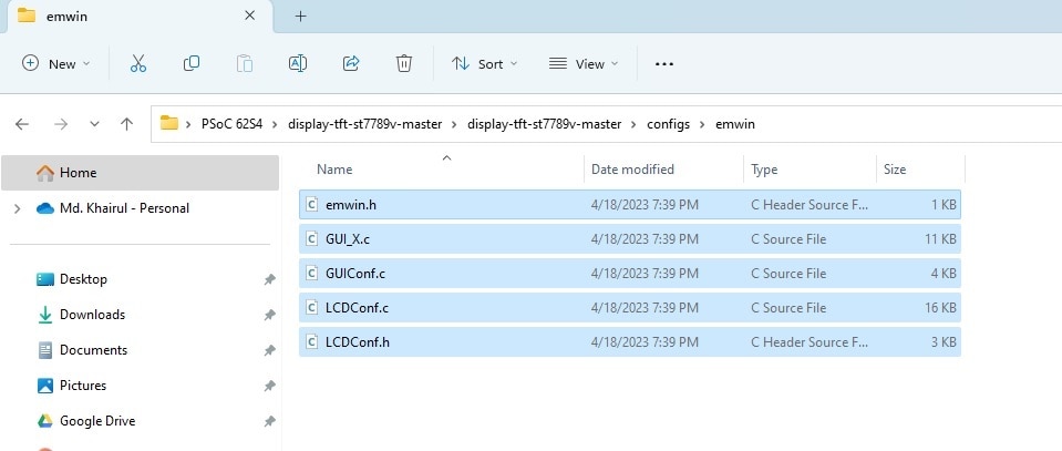
I downloaded the configuration files from this GitHub repository and copied all the configuration files from the configs/emwin directory to the configs directory I just created under root directory of my project.


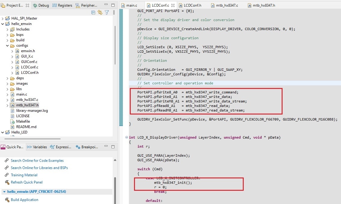
Then I opened the LCDConf.c and LCDConf.h by double clicking the files. This two are the only configuration files you need to modify for successful operation. This LCDConf.c file contains two functions LCD_X_Config() and LCD_X_DisplayDriver() which we need to modify mainly. The main purpose of LCD_X_Config() routine is creating a display driver device and selecting the color conversion routines. Later function is called directly by the display driver. During the initialization process the task of this routine is putting the display controller into operation. A detailed description of the routines are available in the official user guide.
In order to glue the actual hardware with the emWin library we need to provide functions that:
- Initialize the driver – (Tell it what SPI hardware and SPI pins the display is connected to)
- Write data/command bytes and streams to the display driver IC
- Read data streams (which it actually never does) from the display driver IC
For this purpose I made a source file named mtb_hx8347.c which contains lcd initialization function and functions for writing data and command to the display driver IC. This is a short and modified version of lcd_driver which I used in the previous step. This is the source file:
/*
 * mtb_hx8347.c
 *
 *  Created on: Apr 18, 2023
 *  Author: Md. Khairul Alam
 */

#include "cy_pdl.h"
#include "cyhal.h"
#include "cybsp.h"
#include "mtb_hx8347.h"
#include "GUI.h"


extern cyhal_spi_t mSPI;

void lcd_write_byte(uint8_t chByte, uint8_t chCmd)
{
    if (chCmd) {
        __LCD_DC_SET();
    } else {
        __LCD_DC_CLR();
    }
    __LCD_CS_CLR();
        cyhal_spi_send(&mSPI, chByte);
    __LCD_CS_SET();
}


void lcd_write_word(uint16_t hwData)
{
	uint8_t hval = hwData >> 8;
	uint8_t lval = hwData & 0xFF;
    __LCD_DC_SET();
    __LCD_CS_CLR();
        cyhal_spi_send(&mSPI, hval);
        cyhal_spi_send(&mSPI, lval);
    __LCD_CS_SET();
}


void lcd_write_register(uint8_t chRegister, uint8_t chValue)
{
	lcd_write_byte(chRegister, LCD_CMD);
	lcd_write_byte(chValue, LCD_DATA);
}


void lcd_set_cursor(uint16_t hwXpos, uint16_t hwYpos)
{

	if (hwXpos >= LCD_WIDTH || hwYpos >= LCD_HEIGHT) {
				return;
    }

	lcd_write_register(0x02, hwXpos >> 8);
	lcd_write_register(0x03, hwXpos & 0xFF); //Column Start
	lcd_write_register(0x06, hwYpos >> 8);
	lcd_write_register(0x07, hwYpos & 0xFF); //Row Start

}

//clear the lcd with the specified color.
void lcd_clear_screen(uint16_t hwColor)
{
	uint32_t i, wCount = LCD_WIDTH;
	uint8_t hval = hwColor >> 8;
	uint8_t lval = hwColor & 0xFF;
	wCount *= LCD_HEIGHT;


    lcd_set_cursor(0, 0);
    lcd_write_byte(0x22, LCD_CMD);

    __LCD_DC_SET();
    __LCD_CS_CLR();
    for (i = 0; i < wCount; i ++) {
        cyhal_spi_send(&mSPI, hval);
        cyhal_spi_send(&mSPI, lval);
    }
    __LCD_CS_SET();

}


void mtb_hx8347_init(void)
{
    __LCD_DC_OUT();
    __LCD_DC_SET();

    __LCD_CS_OUT();
    __LCD_CS_SET();

    __LCD_BL_OUT();
    __LCD_BL_OFF();

    __LCD_DC_CLR();
    __LCD_CS_CLR();


    lcd_write_register(0xEA,0x00); //PTBA[15:8]
    cyhal_system_delay_ms(5);
    lcd_write_register(0xEB,0x20); //PTBA[7:0]
    cyhal_system_delay_ms(5);
    lcd_write_register(0xEC,0x0C); //STBA[15:8]
    cyhal_system_delay_ms(5);
    lcd_write_register(0xED,0xC4); //STBA[7:0]
    cyhal_system_delay_ms(5);
    lcd_write_register(0xE8,0x38); //OPON[7:0]
    cyhal_system_delay_ms(5);
    lcd_write_register(0xE9,0x10); //OPON1[7:0]
    cyhal_system_delay_ms(5);
    lcd_write_register(0xF1,0x01); //OTPS1B
    cyhal_system_delay_ms(5);
    lcd_write_register(0xF2,0x10); //GEN
    cyhal_system_delay_ms(5);
    //Gamma 2.2 Setting
    lcd_write_register(0x40,0x01); //
    cyhal_system_delay_ms(5);
    lcd_write_register(0x41,0x00); //
    cyhal_system_delay_ms(5);
    lcd_write_register(0x42,0x00); //
    cyhal_system_delay_ms(5);
    lcd_write_register(0x43,0x10); //
    cyhal_system_delay_ms(5);
    lcd_write_register(0x44,0x0E); //
    cyhal_system_delay_ms(5);
    lcd_write_register(0x45,0x24); //
    cyhal_system_delay_ms(5);
    lcd_write_register(0x46,0x04); //
    cyhal_system_delay_ms(5);
    lcd_write_register(0x47,0x50); //
    cyhal_system_delay_ms(5);
    lcd_write_register(0x48,0x02); //
    cyhal_system_delay_ms(5);
    lcd_write_register(0x49,0x13); //
    cyhal_system_delay_ms(5);
    lcd_write_register(0x4A,0x19); //
    cyhal_system_delay_ms(5);
    lcd_write_register(0x4B,0x19); //
    cyhal_system_delay_ms(5);
    lcd_write_register(0x4C,0x16); //
    cyhal_system_delay_ms(5);
    lcd_write_register(0x50,0x1B); //
    cyhal_system_delay_ms(5);
    lcd_write_register(0x51,0x31); //
    cyhal_system_delay_ms(5);
    lcd_write_register(0x52,0x2F); //
    cyhal_system_delay_ms(5);
    lcd_write_register(0x53,0x3F); //
    cyhal_system_delay_ms(5);
    lcd_write_register(0x54,0x3F); //
    cyhal_system_delay_ms(5);
    lcd_write_register(0x55,0x3E); //
    cyhal_system_delay_ms(5);
    lcd_write_register(0x56,0x2F); //
    cyhal_system_delay_ms(5);
    lcd_write_register(0x57,0x7B); //
    cyhal_system_delay_ms(5);
    lcd_write_register(0x58,0x09); //
    cyhal_system_delay_ms(5);
    lcd_write_register(0x59,0x06); //
    cyhal_system_delay_ms(5);
    lcd_write_register(0x5A,0x06); //
    cyhal_system_delay_ms(5);
    lcd_write_register(0x5B,0x0C); //
    cyhal_system_delay_ms(5);
    lcd_write_register(0x5C,0x1D); //
    cyhal_system_delay_ms(5);
    lcd_write_register(0x5D,0xCC); //
    cyhal_system_delay_ms(5);
    //Power Voltage Setting
    lcd_write_register(0x1B,0x1B); //VRH=4.65V
    cyhal_system_delay_ms(5);
    lcd_write_register(0x1A,0x01); //BT (VGH~15V,VGL~-10V,DDVDH~5V)
    cyhal_system_delay_ms(5);
    lcd_write_register(0x24,0x2F); //VMH(VCOM High voltage ~3.2V)
    cyhal_system_delay_ms(5);
    lcd_write_register(0x25,0x57); //VML(VCOM Low voltage -1.2V)
    cyhal_system_delay_ms(5);
    //VCOM offset
    lcd_write_register(0x23,0x88); //for Flicker adjust //can reload from OTP
    cyhal_system_delay_ms(5);
    //Power on Setting
    lcd_write_register(0x18,0x34); //I/P_RADJ,N/P_RADJ, Normal mode 60Hz
    cyhal_system_delay_ms(5);
    lcd_write_register(0x19,0x01); //OSC_EN='1', start Osc
    cyhal_system_delay_ms(5);
    lcd_write_register(0x01,0x00); //DP_STB='0', out deep sleep
    cyhal_system_delay_ms(5);
    lcd_write_register(0x1F,0x88);// GAS=1, VOMG=00, PON=0, DK=1, XDK=0, DVDH_TRI=0, STB=0
    cyhal_system_delay_ms(5);
    lcd_write_register(0x1F,0x80);// GAS=1, VOMG=00, PON=0, DK=0, XDK=0, DVDH_TRI=0, STB=0
    cyhal_system_delay_ms(5);
    lcd_write_register(0x1F,0x90);// GAS=1, VOMG=00, PON=1, DK=0, XDK=0, DVDH_TRI=0, STB=0
    cyhal_system_delay_ms(5);
    lcd_write_register(0x1F,0xD0);// GAS=1, VOMG=10, PON=1, DK=0, XDK=0, DDVDH_TRI=0, STB=0
    cyhal_system_delay_ms(5);
    //262k/65k color selection
    lcd_write_register(0x17,0x05); //default 0x06 262k color // 0x05 65k color
    cyhal_system_delay_ms(5);
    //SET PANEL
    lcd_write_register(0x36,0x00); //SS_P, GS_P,REV_P,BGR_P
    cyhal_system_delay_ms(5);
    //Display ON Setting
    lcd_write_register(0x28,0x38); //GON=1, DTE=1, D=1000
    cyhal_system_delay_ms(5);
    //delay(40);
    lcd_write_register(0x28,0x3F); //GON=1, DTE=1, D=1100
    cyhal_system_delay_ms(5);

    lcd_write_register(0x16,0x18);
    cyhal_system_delay_ms(5);
    //Set GRAM Area
    lcd_write_register(0x02,0x00);
    cyhal_system_delay_ms(5);
    lcd_write_register(0x03,0x00); //Column Start
    cyhal_system_delay_ms(5);
    lcd_write_register(0x04,0x00);
    cyhal_system_delay_ms(5);
    lcd_write_register(0x05,0xEF); //Column End
    cyhal_system_delay_ms(5);
    lcd_write_register(0x06,0x00);
    cyhal_system_delay_ms(5);
    lcd_write_register(0x07,0x00); //Row Start
    cyhal_system_delay_ms(5);
    lcd_write_register(0x08,0x01);
    cyhal_system_delay_ms(5);
    lcd_write_register(0x09,0x3F); //Row End
    cyhal_system_delay_ms(5);

    //lcd_clear_screen(WHITE);
    //lcd_clear_screen(GUI_WHITE);


    __LCD_BL_ON();

}


/*******************************************************************************
 * Writes one byte of data to the software i8080 interface with the LCD_DC pin
 *******************************************************************************/
void mtb_hx8347_write_command(uint8_t data)
{

	__LCD_DC_CLR();

	__LCD_CS_CLR();
	cyhal_spi_send(&mSPI, data);
	__LCD_CS_SET();
}


/*******************************************************************************
 * Writes one byte of data to the software i8080 interface with the LCD_DC pin
 *******************************************************************************/
void mtb_hx8347_write_data(uint8_t data)
{

	__LCD_DC_SET();

    __LCD_CS_CLR();
    cyhal_spi_send(&mSPI, data);
    __LCD_CS_SET();
}


/*******************************************************************************
 * Writes multiple command bytes to the software i8080 interface with the LCD_DC
 * pin set to 0.
 *******************************************************************************/
void mtb_hx8347_write_command_stream(uint8_t *data, int num)
{
    int i;

    __LCD_DC_CLR();

    __LCD_CS_CLR();
    for (i = 0; i < num; i++)
    {
    	cyhal_spi_send(&mSPI, data[i]);
    }
    __LCD_CS_SET();
}


/*******************************************************************************
 * Writes multiple bytes of data to the software i8080 interface with the LCD_DC
 * pin set to 1.
 *******************************************************************************/
void mtb_hx8347_write_data_stream(uint8_t *data, int num)
{
	int i;

	__LCD_DC_SET();

	__LCD_CS_CLR();
	for (i = 0; i < num; i++)
	{
	    cyhal_spi_send(&mSPI, data[i]);
	    //cyhal_spi_transfer(&mSPI, (const uint8_t*)data, num, NULL, 0, 0);
	}
	__LCD_CS_SET();
}


/*******************************************************************************
 * Reads one byte of data from the software i8080 interface with the LCD_DC pin
 * set to 1.
 *******************************************************************************/
uint8_t mtb_hx8347_read_data(void)
{

	CY_ASSERT(0);
	return 0;

}


/*******************************************************************************
 * Reads multiple bytes of data from the software i8080 interface with the LCD_DC
 * pin set to 1.
 *******************************************************************************/
void mtb_hx8347_read_data_stream(uint8_t *data, int num)
{

	//cyhal_gpio_init(CYBSP_USER_LED, CYHAL_GPIO_DIR_OUTPUT, CYHAL_GPIO_DRIVE_STRONG, CYBSP_LED_STATE_OFF);
    //cyhal_gpio_write(CYBSP_USER_LED, 0);
	CY_ASSERT(0);

}


/*******************************************************************************
 * Free all resources used for the software i8080 interface.
 *******************************************************************************/
void mtb_hx8347_free(void)
{
    cyhal_gpio_free(LCD_DC_PIN);
    cyhal_gpio_free(LCD_CS_PIN);
    cyhal_gpio_free(LCD_BL_PIN);
    cyhal_spi_free(&mSPI);

}

/*
cy_rslt_t MTB_E2271CS021_WriteSPIBuffer(uint8_t* data, uint16_t dataLength)
{
    return cyhal_spi_transfer(spi_ptr, (const uint8_t*)data, dataLength, NULL, 0, 0);
}
*/
The corresponding header file is as follows:
/*
 * mtb_hx8347.h
 *
 *  Created on: Apr 18, 2023
 *  Author: Md. Khairul Alam
 */

#pragma once

#include <stdint.h>
#include "cy_result.h"
#include "cyhal.h"
#include "cybsp.h"


#if defined(__cplusplus)
extern "C"
{
#endif


#define LCD_CMD					    0
#define LCD_DATA				    1

#define WHITE						0xFFFF
#define BLACK						0x0000
#define BLUE                        0x001F

#define LCD_WIDTH    240
#define LCD_HEIGHT   320

#define LCD_BL_PIN CYBSP_D9
#define LCD_DC_PIN CYBSP_D7
#define LCD_CS_PIN CYBSP_D10


#define __LCD_CS_OUT()      cyhal_gpio_init(LCD_CS_PIN, CYHAL_GPIO_DIR_OUTPUT, CYHAL_GPIO_DRIVE_STRONG, false)
#define __LCD_DC_OUT()      cyhal_gpio_init(LCD_DC_PIN, CYHAL_GPIO_DIR_OUTPUT, CYHAL_GPIO_DRIVE_STRONG, false)
#define __LCD_BL_OUT()      cyhal_gpio_init(LCD_BL_PIN, CYHAL_GPIO_DIR_OUTPUT, CYHAL_GPIO_DRIVE_STRONG, false)

#define __LCD_CS_CLR()      cyhal_gpio_write(LCD_CS_PIN, false)
#define __LCD_CS_SET()      cyhal_gpio_write(LCD_CS_PIN, true)
#define __LCD_DC_CLR()      cyhal_gpio_write(LCD_DC_PIN, false)
#define __LCD_DC_SET()      cyhal_gpio_write(LCD_DC_PIN, true)
#define __LCD_BL_OFF()		cyhal_gpio_write(LCD_BL_PIN, false)
#define __LCD_BL_ON()		cyhal_gpio_write(LCD_BL_PIN, true)

/**
* \addtogroup group_board_libs TFT Display
* \{
* APIs for controlling the TFT display on the board.
*/


/**
 * Initializes GPIOs for the software i8080 8-bit interface.
 * @param[in] pins Structure providing the pins to use for the display
 * @return CY_RSLT_SUCCESS if successfully initialized, else an error about
 * what went wrong
 */
void mtb_hx8347_init(void);

/**
 * Sets value of the display Reset pin.
 * @param[in] value The value to set on the pin
 */
//void mtb_hx8347_write_reset_pin(bool value);

/**
 * Writes one byte of data to the software i8080 interface with the LCD_DC pin
 * set to 0. Followed by a low pulse on the NWR line to complete the write.
 * @param[in] command The command to issue to the display
 */
void mtb_hx8347_write_command(uint8_t command);

/**
 * Writes one byte of data to the software i8080 interface with the LCD_DC pin
 * set to 1. Followed by a low pulse on the NWR line to complete the write.
 * @param[in] data The value to issue to the display
 */
void mtb_hx8347_write_data(uint8_t data);

/**
 * Writes multiple command bytes to the software i8080 interface with the LCD_DC
 * pin set to 0.
 * @param[in] data Pointer to the commands to send to the display
 * @param[in] num  The number of commands in the data array to send to the display
 */
void mtb_hx8347_write_command_stream(uint8_t *data, int num);

/**
 * Writes multiple bytes of data to the software i8080 interface with the LCD_DC
 * pin set to 1.
 * @param[in] data Pointer to the data to send to the display
 * @param[in] num  The number of bytes in the data array to send to the display
 */
void mtb_hx8347_write_data_stream(uint8_t *data, int num);

/**
 * Reads one byte of data from the software i8080 interface with the LCD_DC pin
 * set to 1.
 * @return The byte read from the display
 */
uint8_t mtb_hx8347_read_data(void);

/**
 * Reads multiple bytes of data from the software i8080 interface with the LCD_DC
 * pin set to 1.
 * @param[in,out]   data Pointer to where to store the bytes read from the display
 * @param[in]       num  The number of bytes to read from the display
 */
void mtb_hx8347_read_data_stream(uint8_t *data, int num);

/**
 * Free all resources used for the software i8080 interface.
 */
void mtb_hx8347_free(void);

/** \} group_board_libs */

void lcd_write_byte(uint8_t chByte, uint8_t chCmd);
void lcd_write_word(uint16_t hwData);
void lcd_write_register(uint8_t chRegister, uint8_t chValue);
void lcd_set_cursor(uint16_t hwXpos, uint16_t hwYpos);
void lcd_clear_screen(uint16_t hwColor);


#if defined(__cplusplus)
}
#endif

/* [] END OF FILE */
After adding this two files inside the root directory I modified the LCDConfig.c. As I already added the lcd initialization function in the mtb_hx8347.c file, first I removed the initialization routine from the LCDConfig.c file.
Then I modified the LCD_X_Config() function and LCD_X_DisplayDriver() function as follows:

Finally I modified the main.c file as follows:
/*******************************************************************************
* Header Files
*******************************************************************************/
#include "cy_pdl.h"
#include "cyhal.h"
#include "cybsp.h"
#include "mtb_hx8347.h"
#include "GUI.h"


/*******************************************************************************
* Macros
*******************************************************************************/
/* SPI baud rate in Hz */
#define SPI_FREQ_HZ                (1000000UL)
/* Delay of 1000ms between commands */
#define CMD_TO_CMD_DELAY           (1000UL)
/* SPI transfer bits per frame */
#define BITS_PER_FRAME             (8)


cy_rslt_t result;
cyhal_spi_t mSPI;


void handle_error(uint32_t status)
{
    if (status != CY_RSLT_SUCCESS)
    {
        CY_ASSERT(0);
    }
}


int main(void)
{


    /* Initialize the device and board peripherals */
    result = cybsp_init();
    /* Board init failed. Stop program execution */
    handle_error(result);

    /* Enable interrupts */
    __enable_irq();

    result = cyhal_spi_init(&mSPI,CYBSP_SPI_MOSI,CYBSP_SPI_MISO,CYBSP_SPI_CLK,
                                    NC,NULL,BITS_PER_FRAME,
                                    CYHAL_SPI_MODE_11_MSB,false);
    handle_error(result);

    result = cyhal_spi_set_frequency(&mSPI, SPI_FREQ_HZ);
    handle_error(result);


    GUI_Init();
    GUI_SetBkColor(GUI_RED);
    GUI_SetColor(GUI_WHITE);
    GUI_SetBkColor(GUI_BLACK);
    GUI_SetFont(GUI_FONT_32B_1);
    GUI_SetTextAlign(GUI_TA_CENTER);
    GUI_DispStringAt("Hello World", GUI_GetScreenSizeX()/2,GUI_GetScreenSizeY()/2 - GUI_GetFontSizeY()/2);


    for (;;)
    {


        /* Give delay between commands */
        //cyhal_system_delay_ms(500);

    }
}
After saving all the modifications I clicked to the build button but I was getting the following error:

I was not sure why I was getting that error. I checked for the GUIConf.h file and found the file in the right place. After doing some research I found that (here) I need to add the following line in the Makefile.

So, I added the above line in the Makefile of my project. The project was then successfully build but nothing was seen in the display.

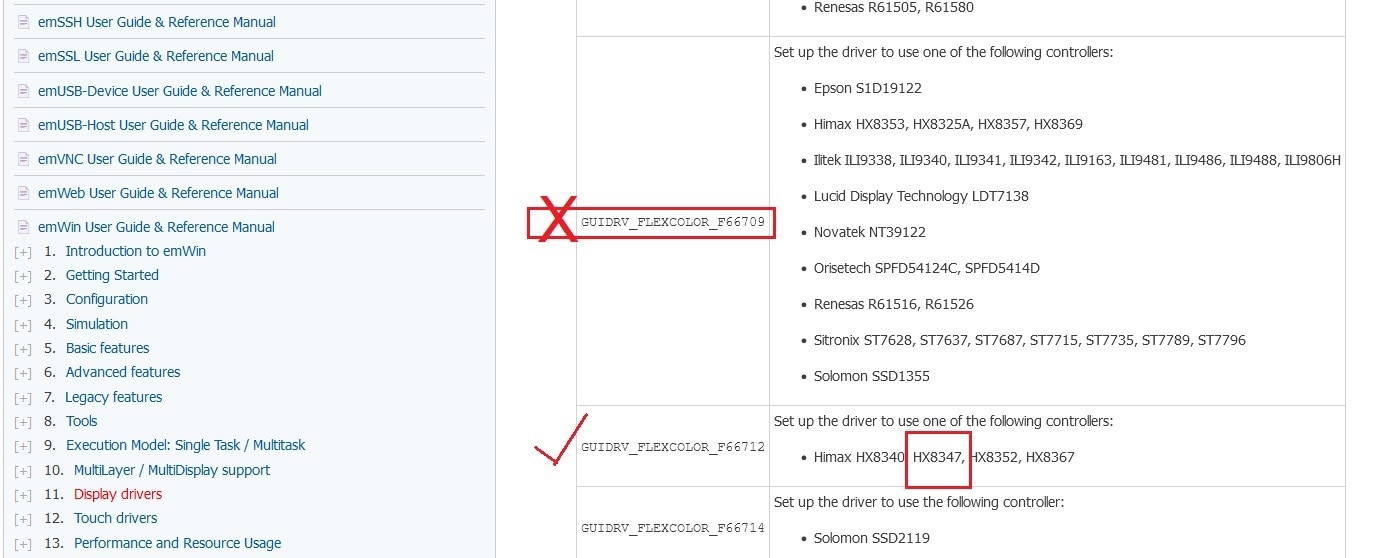
After sending few hours on it I was a bit frustrated. I was reading the emWin user manual for any possible mistakes or solution. Fortunately I understood that I need to change the parameter of the following function inside the LCDConf.c file as my display driver is different from the st7789v.
GUIDRV_FlexColor_SetFunc(pDevice, &PortAPI, GUIDRV_FLEXCOLOR_F66709, GUIDRV_FLEXCOLOR_M16C0B8);

As my driver is HX8347 so I need to change the third parameter of the above function from GUIDRV_FLEXCOLOR_F66709 to GUIDRV_FLEXCOLOR_F66712. So, I modified the function parameter accordingly.

And I got the output! But I seen some color mismatch between blue and red on the display. After doing some more research I finally got the solution of that problem also.

I changed one define statement in the LCDConf.c file as follows and the problem was solved.

This was the final result:

