The PSoC 62S4 Pioneer Kit includes a dual-core PSoC MCU which includes Arm® Cortex®-M4 and Cortex®-M0+ cores, as well as an inter-processor communication (IPC) module. A dual-core architecture provides the flexibility to help improve system performance and efficiency and reduce power consumption.
The block diagram given below shows the typical architecture of a PSoC dual-core CPU. Details are available in PSoC 6 MCU dual-core system design guide.

A dual-core architecture, along with the DMA and cryptography (Crypto) bus masters, presents unique opportunities for system-level design and performance optimization in a single MCU. In a dual-core CPU we can perform multiple task simultaneously and Enable and disable CPUs to minimize the power draw.
Most of the dual-core architecture we find a high performance core and a low performance core. We can perform high computation intensive work like graphics and sensor data processing using high performance core (e.g. CM4 core) and low computation intensive work like sensor reading using a low performance core (e.g. CM0+). That improves the system performance and reduce the power consumption. I am going to use this features in my project. I will use CM0+ core for reading the capsense button and CM4 for driving graphics display and audio codec.
For my project data exchange between two cores is required and this is the getting started blog on inter processor communication. In PSOC MCU inter-processor communication happens by a special MCU block named as inter-processor communication (IPC) block, which implements semaphores and mutual exclusion (mutexes) in hardware.
In inter-processor communication either two processors (core) share a common resource such as UART block or two processors/core can exchange data between them. In ModusToolbox we can use IPC driver to implement a message pipe in PSoC 6 MCU to send messages between two cores. For using a common resource by two cores we can implement a semaphore in PSoC 6 MCU. The semaphore is used as a lock to control access to a resource shared by the CPUs and synchronize the initialization instructions.
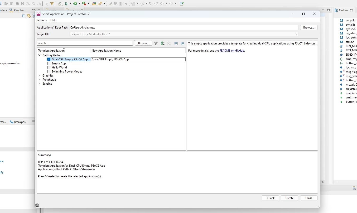
As I intend to send data from one core to other I will focus on IPC Pipe. I started with reading this guide. Then I created Dual-CPU Empty PSoC 6 App from Getting Started example from New Application tab.
I found this IPC message pipe example from GitHub. I read the README.md file carefully for understanding the functionality of the example. I downloaded the project from the GitHub and added to ModusToolbox IDE but did not find any build option for the example. I am not sure yet either this can be directly use as a ModusToolbox project or not. Taking the help from project documentation and PSoC 6 MCU dual-core system design guide I started to modify the Dual-CPU Empty PSoC 6 App for importing the functionality from IPC message pipe example to my project. First I copied the source file from both app_cm0p and app_cm4 directories and pasted accordingly to my empty project. I then added CY_IPC_DEFAULT_CFG_DISABLE=1 command to the Makefile of cm0p app.

I did the same for cm4 app Makefile.

So, the Makefile of both CPUs adds CY_IPC_DEFAULT_CFG_DISABLE=1 in the DEFINES variable. This disables the default IPC configuration that comes with the BSP.
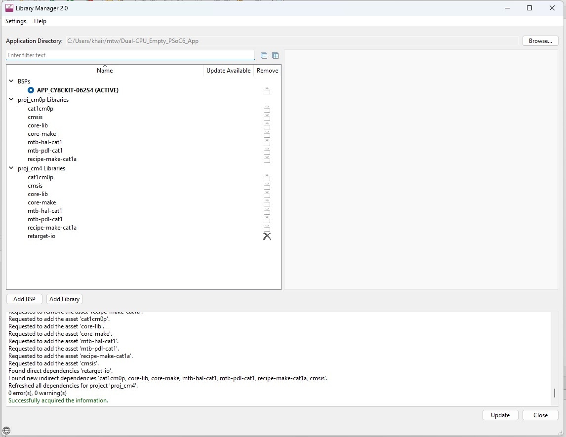
After modifying the Makefiles I installed retarget-io library to cm4 app using the library manager.
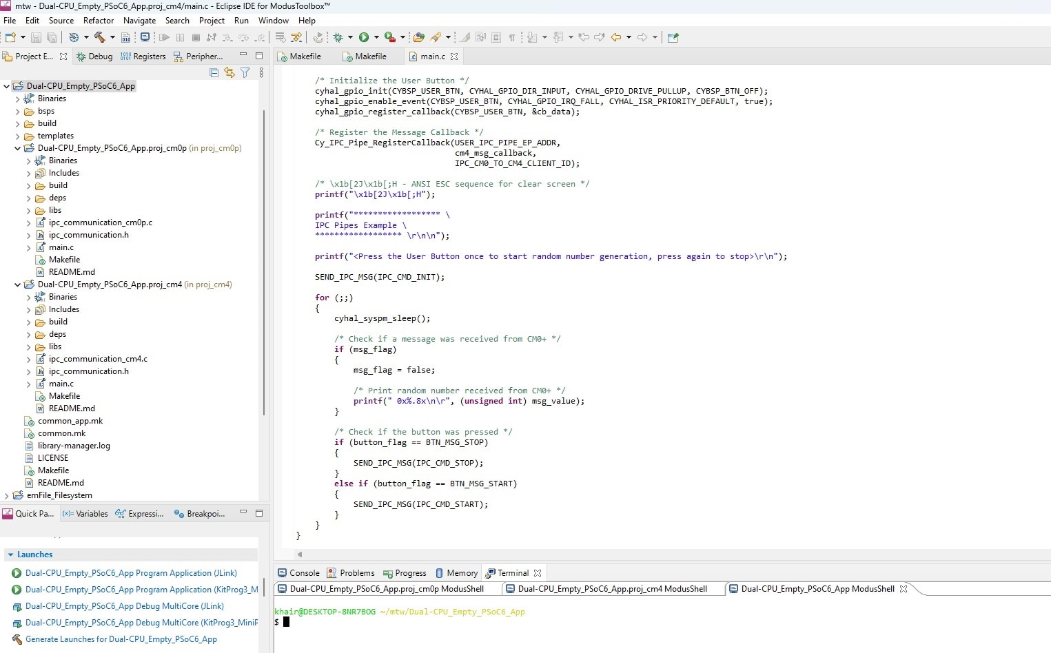
Finally, I copied ipc_communication source to both of the app. The complete project structure looks like following:
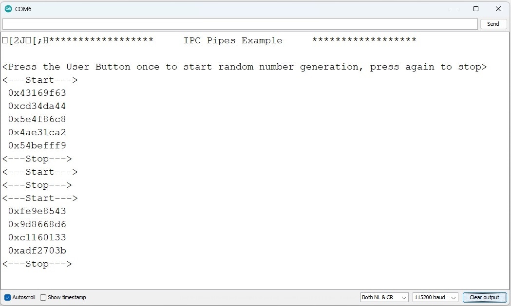
For observing the result I used the Arduino serial monitor and this is the serial monitor output:
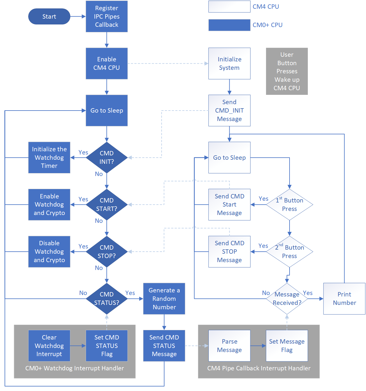
In this code example, the CM4 CPU is the primary CPU, which is responsible to initialize the system. CM0+ waits for CM4 to complete the system initialization by waiting for an IPC command.
The CM0+ CPU uses a watchdog timer to periodically wake itself up from sleep. Once it wakes up, it generates a 32-bit random number using the crypto block and sends it to the CM4 CPU. When CM4 receives a message from CM0+, it parses it, and prints the random number to the terminal.
The random number generation by CM0+ can be enabled or disabled by CM4 CPU. The CM4 CPU checks if the user has pressed the kit button. When a button press is detected, CM4 informs CM0+ to start creating random numbers. When the button is released, CM4 instructs CM0+ to stop creating random numbers.
The following Flowchart shows the details operation of the code (this flowchart is taken from the GitHub link of the project):
In the next blog, I will try to read capsense button using CM0+ and send the result to CM4 using IPC pipe.
