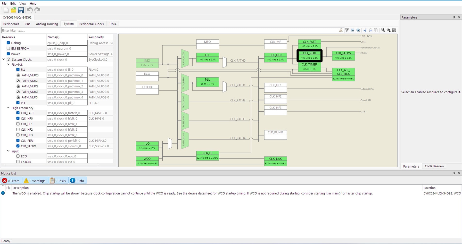
Now that we have the timings, we can do the math in order to implement a PWM channel to generate the HSync signal on P9_0. The PWM can be generated by the TCPWM peripheral which uses the peripheral clock. When we start an "Empty" project for CY8CKIT-062S4 in ModusToolbox, the essential configuration sets the peripheral clock to 100MHz +/- 2.4%

Wow, 100MHz +/- 2.4% what does it mean? Does it mean that the peripheral clock oscillates between 97.6MHz and 102.4 MHz? I think that this is not good, but luckily I can stabilize it more if I customize the FLL clock changing Automatic to Manual configuration, and setting 'Lock tolerance' to 0. This reduces the variance to 0.4%, which corresponds to 400kHz, much much better.
I am worried about this because the counter of the TCPWM is ruled by this clock, and the HSync pulse width will oscillate also. 2.4% will generate an oscillation of 91.5ns, while 0.4% will instead generate an oscillation of 15.2 ns. That's much better and the signal should be stable.
For now, having set the Lock Tolerance to 0, let's consider the frequency to be 100MHz. Every cycle of the TCPWM counter should be 10ns long. That said, the PWM should have a period of (31777ns / 10ns) 3177 or rounded 3178 cycles. While the pulse length should be (3813ns / 10ns) 381 cycles.
According to the HSync pulse the VGA signal expects

the PWM should be HIGH, and then go LOW for 381 cycles at the end of the period. Now we can consider in our mind that the whole line starts right after the HSync pulse, with the back porch. It's easier.
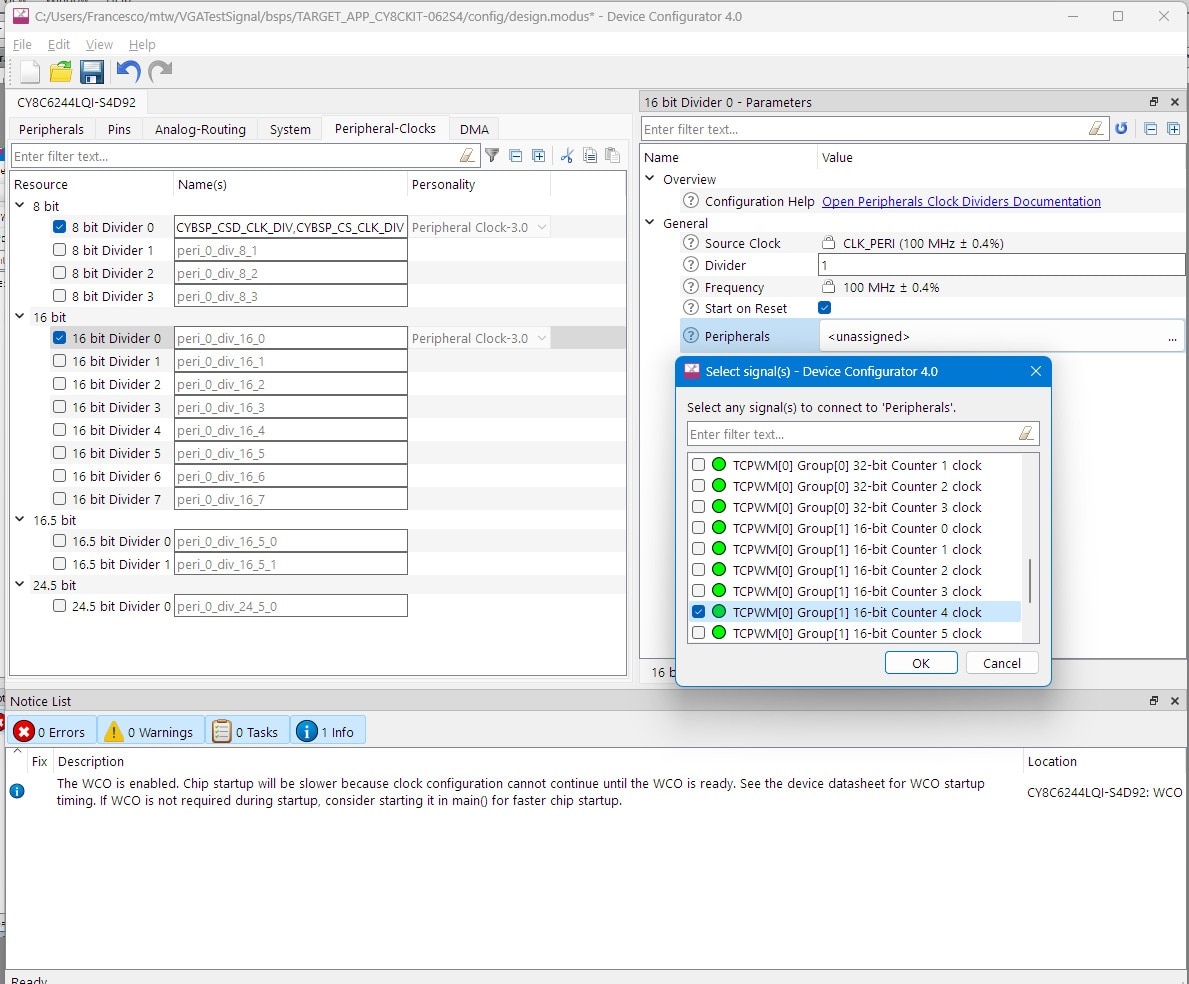
The ModusToolbox is really good for the configuration of peripherals and offers the "Device Configurator" for this purpose. A TCPWM counter needs a clock source to work, so I need one to set up and assign it to the TCPWM peripheral.

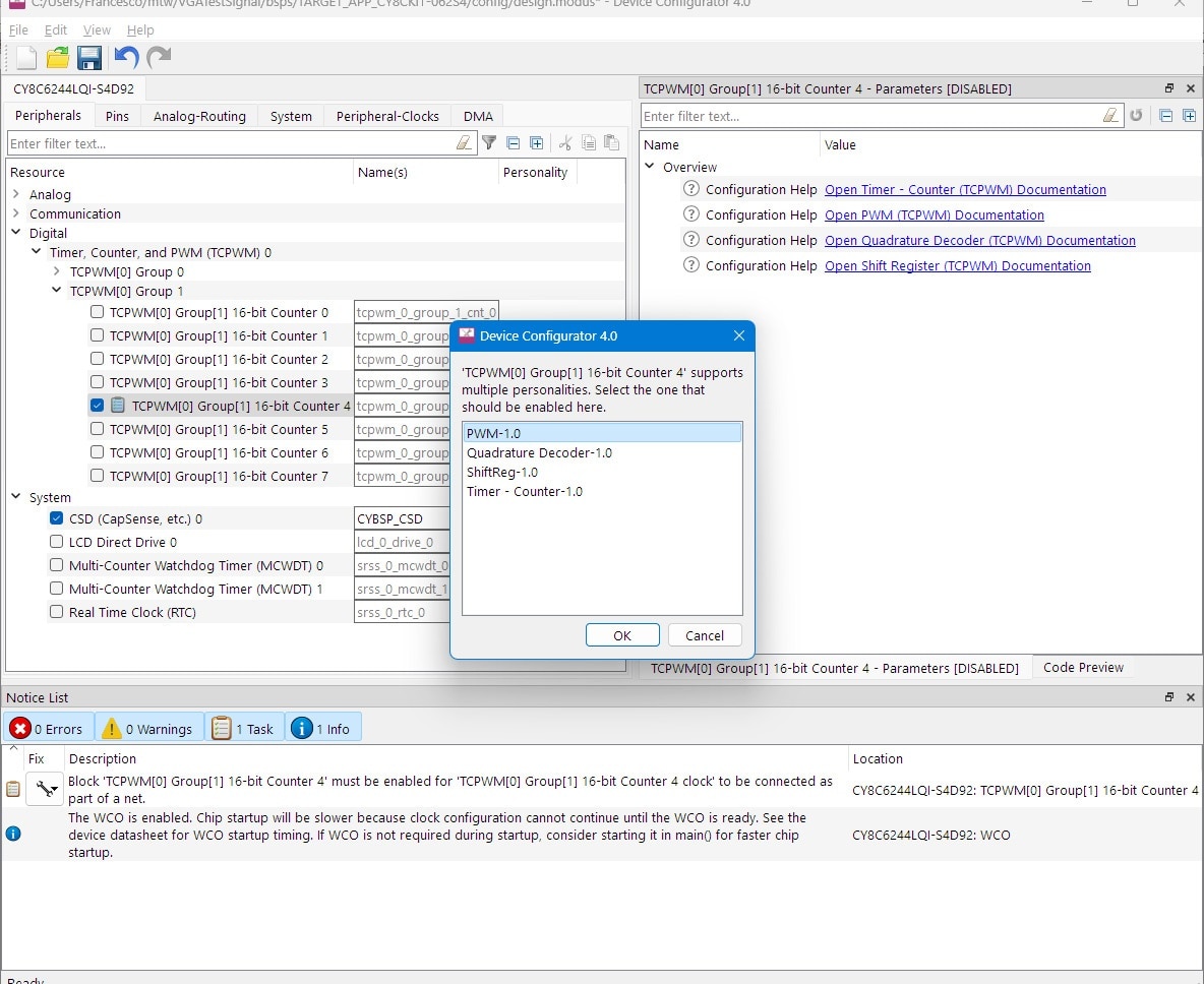
I have selected the TCPWM 0 Group 1 Counter 4 because it's an alternate function of the pin P9_0 as stated in the datasheet.

Next, I enabled the TCPWM 0 Group 1 Counter 4 and selected the PWM counter type.

Now it's a question of setting the parameters that I calculated before. So I need to set some parameters:
- the period of the counter = 3177.
- the right-aligned "Counter Compare 0" value = 381.
- the overflow interrupt (when the counter overflows the period value).
- the polarity of the PWM wave inverted (so the wave starts HIGH, then the pulse is LOW).
- the PWM output line = P9_0 pin.
Done, don't forget that everything defined here will be "global" and can be used in the project:

In the next part, I will write the code to enable the PWM signal in the application.

