element14 Community
element14 Community
    Register Log In
  • Site
  • Search
  • Log In Register
  • Community Hub
    Community Hub
    • What's New on element14
    • Feedback and Support
    • Benefits of Membership
    • Personal Blogs
    • Members Area
    • Achievement Levels
  • Learn
    Learn
    • Ask an Expert
    • eBooks
    • element14 presents
    • Learning Center
    • Tech Spotlight
    • STEM Academy
    • Webinars, Training and Events
    • Learning Groups
  • Technologies
    Technologies
    • 3D Printing
    • FPGA
    • Industrial Automation
    • Internet of Things
    • Power & Energy
    • Sensors
    • Technology Groups
  • Challenges & Projects
    Challenges & Projects
    • Design Challenges
    • element14 presents Projects
    • Project14
    • Arduino Projects
    • Raspberry Pi Projects
    • Project Groups
  • Products
    Products
    • Arduino
    • Avnet & Tria Boards Community
    • Dev Tools
    • Manufacturers
    • Multicomp Pro
    • Product Groups
    • Raspberry Pi
    • RoadTests & Reviews
  • About Us
    About the element14 Community
  • Store
    Store
    • Visit Your Store
    • Choose another store...
      • Europe
      •  Austria (German)
      •  Belgium (Dutch, French)
      •  Bulgaria (Bulgarian)
      •  Czech Republic (Czech)
      •  Denmark (Danish)
      •  Estonia (Estonian)
      •  Finland (Finnish)
      •  France (French)
      •  Germany (German)
      •  Hungary (Hungarian)
      •  Ireland
      •  Israel
      •  Italy (Italian)
      •  Latvia (Latvian)
      •  
      •  Lithuania (Lithuanian)
      •  Netherlands (Dutch)
      •  Norway (Norwegian)
      •  Poland (Polish)
      •  Portugal (Portuguese)
      •  Romania (Romanian)
      •  Russia (Russian)
      •  Slovakia (Slovak)
      •  Slovenia (Slovenian)
      •  Spain (Spanish)
      •  Sweden (Swedish)
      •  Switzerland(German, French)
      •  Turkey (Turkish)
      •  United Kingdom
      • Asia Pacific
      •  Australia
      •  China
      •  Hong Kong
      •  India
      •  Japan
      •  Korea (Korean)
      •  Malaysia
      •  New Zealand
      •  Philippines
      •  Singapore
      •  Taiwan
      •  Thailand (Thai)
      •  Vietnam
      • Americas
      •  Brazil (Portuguese)
      •  Canada
      •  Mexico (Spanish)
      •  United States
      Can't find the country/region you're looking for? Visit our export site or find a local distributor.
  • Translate
  • Profile
  • Settings
At The Core Design Challenge
  • Challenges & Projects
  • Design Challenges
  • At The Core Design Challenge
  • More
  • Cancel
At The Core Design Challenge
Blog ATCDC: Digimorf, Day 13, The project SEGA SG-1000 Emulator, VGA on PSoC62S4 Pioneer kit - part 3
  • Blog
  • Forum
  • Documents
  • Leaderboard
  • Polls
  • Files
  • Members
  • Mentions
  • Sub-Groups
  • Tags
  • More
  • Cancel
  • New
Join At The Core Design Challenge to participate - click to join for free!
  • Share
  • More
  • Cancel
Group Actions
  • Group RSS
  • More
  • Cancel
Engagement
  • Author Author: Digimorf
  • Date Created: 12 Mar 2023 9:46 PM Date Created
  • Views 712 views
  • Likes 6 likes
  • Comments 2 comments
  • infineon
  • PSoCTm︎ 62 MCU
  • timer
  • pwm
  • vga
Related
Recommended

ATCDC: Digimorf, Day 13, The project SEGA SG-1000 Emulator, VGA on PSoC62S4 Pioneer kit - part 3

Digimorf
Digimorf
12 Mar 2023
ATCDC: Digimorf, Day 13, The project SEGA SG-1000 Emulator, VGA on PSoC62S4 Pioneer kit - part 3

Bad news,

what I have thought to work actually doesn't. As I was worried, the variation of the frequency generates a very shaky and unstable video signal. I am not showing here the code implemented so there won't be confusion, but things don't work and probably I have to change the clock source, the peripheral clock frequency, and the PWM signal.

Let's see what's going on...

You don't have permission to edit metadata of this video.
Edit media
x
image
Upload Preview
image

The video signal is hooked by this CRT monitor that I always use in my tests for VGA video generation. The problem here is that horizontally, and apparently, randomly the lines of the image are drawn from different starting points. In my experience, this defect may be caused by two problems.

1. Random interrupt latency causes the lines to be drawn at different starting points.

2. Frequency instability.

Frankly, I don't think it's a question of interrupt latency, the main loop of the application is empty, and nothing else is running. So it might be the configuration of the clock.

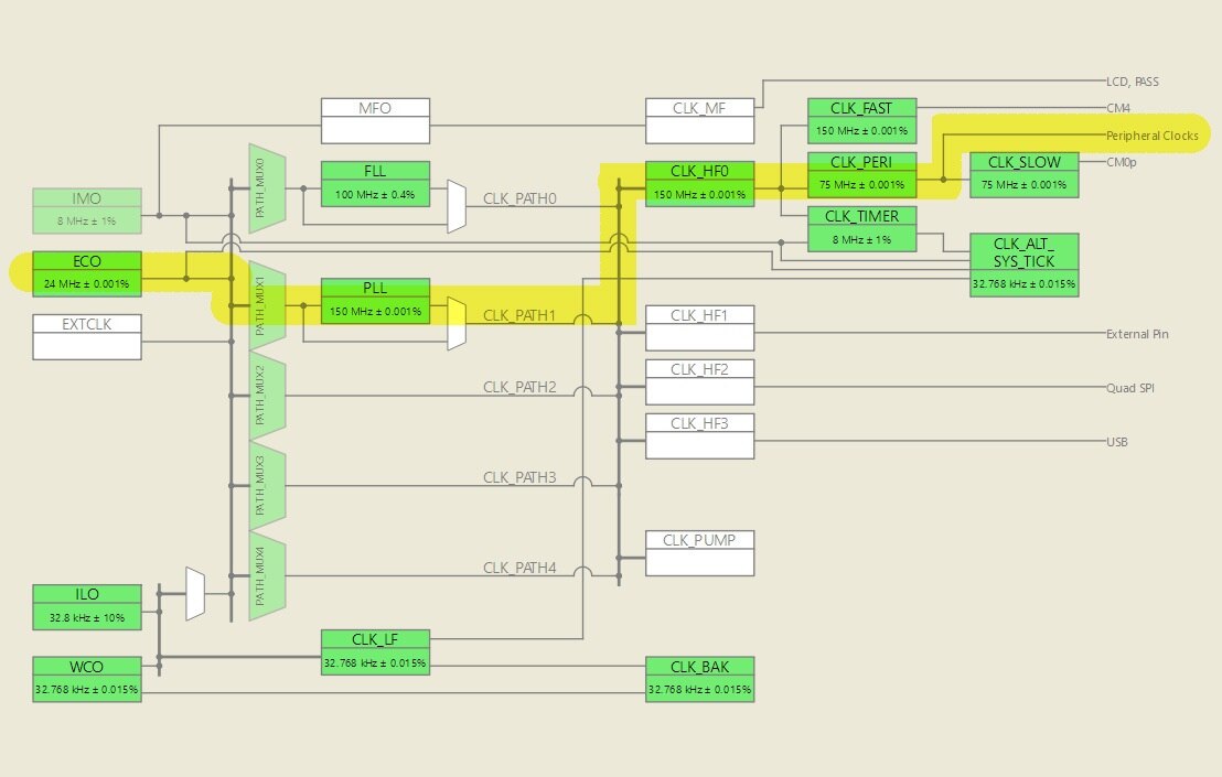
I had some concerns about a possible clock configuration issue when I saw that both cores have been configured at 100MHz in the "Empty project" example where I started from. This MCU is said to have the cm0+ clocked at 100MHz, and the cm4 clocked at 150MHz but in this example, it isn't.

I went a bit deeper into the clocking system, and the FLL which is used here as a source clock can't go beyond 100MHz. The PLL must be used if you want to clock the cm4 at 150Mhz, but at that point, as consequence, the peripheral clock goes off the allowed range (<=100MHz), so you have to set its divider to 2, at least. 

I used the IMO clock source (8MHz) for the FLL so far, but wait, I saw that the kit has the ECO clock connected to a 24MHz crystal, the ECS-240-8-30B-CKM. In the manual there is the schematic:

image

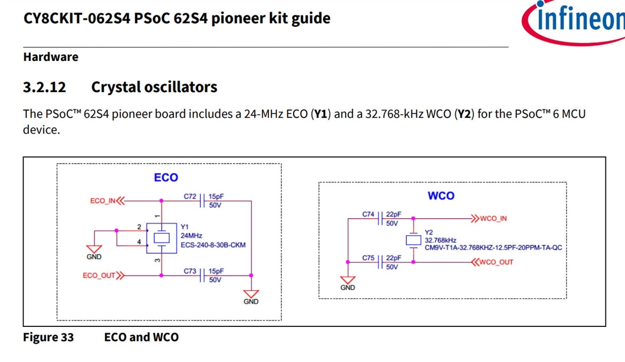
and 24MHz clock could give me more chances to obtain a good frequency to use for my VGA signal. So I configured the clocking system to use the ECO clock.

image

The great thing that I saw in this configurator is that you can set several parameters for the crystal!
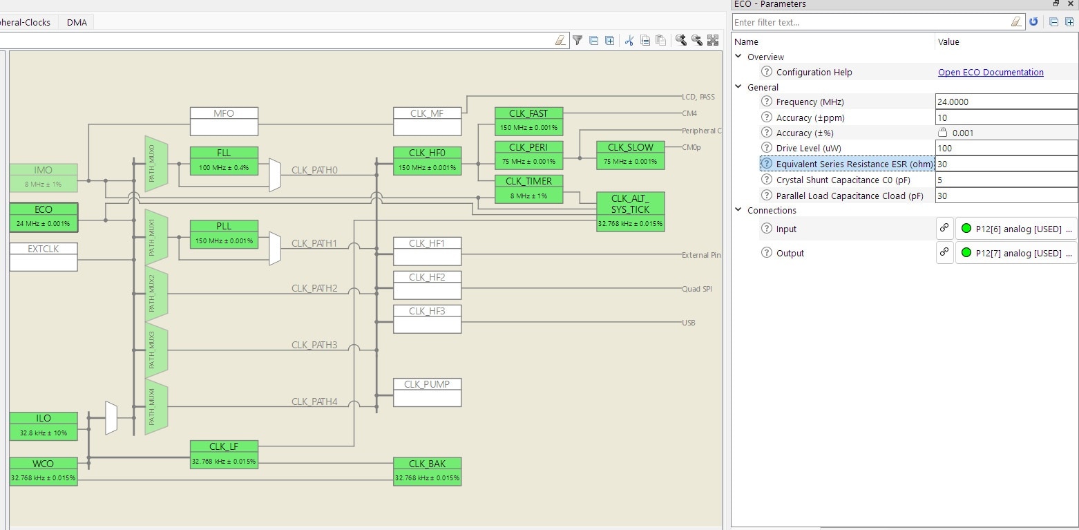
image

HOW COOL IS THAT?

I immediately downloaded the datasheet of the crystal to get the correct parameters, here's the link:

ecx_53b.pdf

After that, I had to redo the math again for the TCPWM counter in the same way I did in my previous post. This time I will configure the PWM as asymmetrical using CC0 and CC1 as limits for the negative pulse, so I can perfectly align the HSync at the end of the scanline, between the front porch and the back porch. Moreover, I can use the CC0 match (when the sync pulse start) IRQ to handle the scanline counter, and the TC IRQ to start sending pixels.

Now the variation of the frequency is 0.001% of 75MHz or 750Hz, so the scanline should be stable enough.

Let's see how it goes now...

You don't have permission to edit metadata of this video.
Edit media
x
image
Upload Preview
image

Sorry for the super quick video but, yeah, success! Stable, nice, and clean. 

In the next part the code.

  • Sign in to reply

Top Comments

  • dougw
    dougw over 3 years ago +1
    Nice work around.
  • Digimorf
    Digimorf over 3 years ago in reply to dougw

    Thanks, this can be useful to users Blush

    • Cancel
    • Vote Up 0 Vote Down
    • Sign in to reply
    • More
    • Cancel
  • dougw
    dougw over 3 years ago

    Nice work around. 

    • Cancel
    • Vote Up +1 Vote Down
    • Sign in to reply
    • More
    • Cancel
element14 Community

element14 is the first online community specifically for engineers. Connect with your peers and get expert answers to your questions.

  • Members
  • Learn
  • Technologies
  • Challenges & Projects
  • Products
  • Store
  • About Us
  • Feedback & Support
  • FAQs
  • Terms of Use
  • Privacy Policy
  • Legal and Copyright Notices
  • Sitemap
  • Cookies

An Avnet Company © 2026 Premier Farnell Limited. All Rights Reserved.

Premier Farnell Ltd, registered in England and Wales (no 00876412), registered office: Farnell House, Forge Lane, Leeds LS12 2NE.

ICP 备案号 10220084.

Follow element14

  • X
  • Facebook
  • linkedin
  • YouTube