


This is a good rainy day for examining code and parameters with a good cup of coffee and nice music.
The video frame is stable, even if the naive method that I used now for sending RGB data to the monitor is not what I have in mind. Anyway, I will explain it later. I want now to update you about the HSync question and about the parameters used with the new clock source.
Let's recap. The clock source used here is the ECO which is connected to the 24MHz external oscillator. The Peripheral clock generated is 75MHz +/- 0.001%. Now with this clock, the cycle of the TCPWM counter is (1/75MHz)13.33ns.
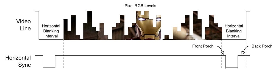
Looking back at the VGA timings for the 640x480x60Hz resolution:
Horizontal timing (line)
Polarity of horizontal sync pulse is negative (HIGH-LOW-HIGH).
| Scanline part | Pixels | Time [µs] |
| Visible area | 640 | 25.422045680238 |
| Front porch | 16 | 0.63555114200596 |
| Sync pulse | 96 | 3.8133068520357 |
| Back porch | 48 | 1.9066534260179 |
| Whole line | 800 | 31.777557100298 |
we can recalculate the period of the PWM cycle, but now we can go ahead and improve the PWM waveform using both CC0 and CC1 to better align the HSync pulse.
CC0 = Active Area + Front Porch
CC0 = 25422ns + 636ns = 26058ns
CC1 = CC0 + Synch
CC1 = 26058ns + 3813ns = 29871ns
TC = CC1 + Back Porch
TC = 29871ns + 1906ns = 31777ns
Now, thinking in terms of TCPWM counter cycles (13.33ns):
CC0 = 26058ns / 13.33ns = 1955
CC1 = 29871ns / 13.33ns = 2240
TC = 31777ns / 13.33ns = 2383

In order to do this we need to configure the TCPWM as asymmetrical, as seen in the technical reference manual:
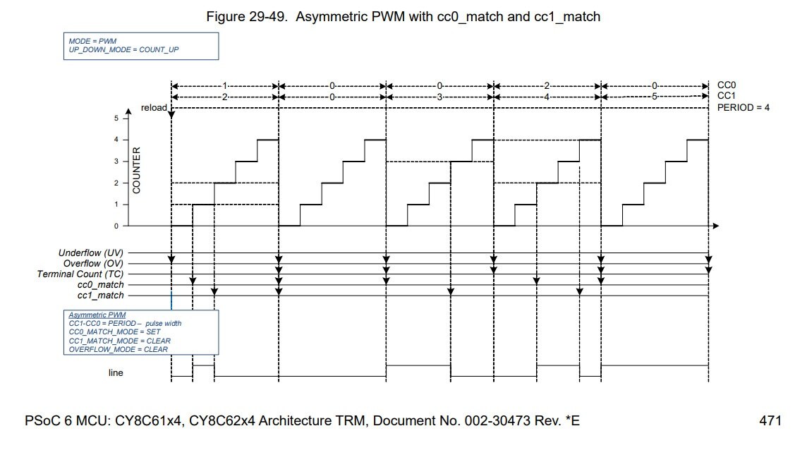
Again the Device Configurator in ModusToolbox comes helpful, and we can set parameters easily:
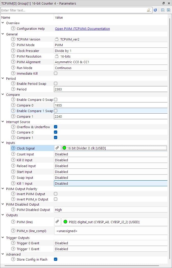
This setting tab will generate the code of definitions and globals that are included automatically in the project. You can copy them for reference in the Code Preview tab. My suggestion is to copy the names/definitions/globals into a comment block and put it into your routine that initializes the TCPWMcounter.
/*
                          tcpwm_0_group_1_cnt_4_HW
                          tcpwm_0_group_1_cnt_4_NUM
                          tcpwm_0_group_1_cnt_4_IRQ
cy_stc_tcpwm_pwm_config_t tcpwm_0_group_1_cnt_4_config
cyhal_resource_inst_t     tcpwm_0_group_1_cnt_4_obj

                          init_cycfg_peripherals
                          reserve_cycfg_peripherals
*/
Here we come at the real code that I used to show color stripes on a VGA monitor.
void HSyncPWM_Init()
{
  /*----------------------------------------------------------------------*/
  cy_stc_sysint_t HSyncInt_cfg = {
      tcpwm_0_group_1_cnt_4_IRQ,
      0
  };

  /*----------------------------------------------------------------------*/
  /* Initialize the interrupt with vector at Interrupt_Handler_Port0() */
  Cy_SysInt_Init(&HSyncInt_cfg, (cy_israddress)HSyncPWM_IRQHandler);


  /* Enable the interrupt */
  NVIC_EnableIRQ(HSyncInt_cfg.intrSrc);

  /*----------------------------------------------------------------------
   *
      Horizontal :
             :_________________       :
             |                 |      :
    _________|  VIDEO          |______:___
             :                        :
    ____   __:___________________   __:___
        |_|  :                   |_|  :
             :               CCn-0 1  :TC

    CC0  1955
    CC1  2240  CC1-CC0 = HSync pulse
    TC   2383  TC-CC1 = Back porch
               TC = RGB data starts

   ----------------------------------------------------------------------*/
  if (CY_TCPWM_SUCCESS != Cy_TCPWM_PWM_Init(tcpwm_0_group_1_cnt_4_HW,
                                            tcpwm_0_group_1_cnt_4_NUM,
                                            &tcpwm_0_group_1_cnt_4_config)) {}

  /* Enable the initialized PWM */
  Cy_TCPWM_PWM_Enable(tcpwm_0_group_1_cnt_4_HW,
                      tcpwm_0_group_1_cnt_4_NUM);

  /* Then start the PWM */
  Cy_TCPWM_TriggerStart_Single(tcpwm_0_group_1_cnt_4_HW,
                               tcpwm_0_group_1_cnt_4_NUM);
  /*----------------------------------------------------------------------*/
}
Some globals to add:
/*******************************************************************************
* Global Variables
*******************************************************************************/
GPIO_PRT_Type* portAddr = GPIO_PRT10;

volatile uint16_t gScanline = 0;
volatile uint16_t x = 0;
And the ISR:
void HSyncPWM_IRQHandler(void)
{
  /* Get all the enabled pending interrupts */
  uint32_t interrupts =
      Cy_TCPWM_GetInterruptStatusMasked(tcpwm_0_group_1_cnt_4_HW,
                                        tcpwm_0_group_1_cnt_4_NUM);

  if (CY_TCPWM_INT_ON_CC0 & interrupts)
  {
    portAddr->OUT = 0;

    switch (gScanline) {

      case 0: cyhal_gpio_write(P9_1, false); break;
      case 2: cyhal_gpio_write(P9_1, true); break;
    }

    gScanline++;
    if (gScanline == 525) gScanline = 0;
  }

  if (CY_TCPWM_INT_ON_TC & interrupts)
  {
    if ((gScanline >= 35) && (gScanline < 525)) {
      x = 256;
      while (x--) {
        portAddr->OUT = x;
      }

      portAddr->OUT = 0;
    }
  }

  /* Clear the interrupt */
  Cy_TCPWM_ClearInterrupt(tcpwm_0_group_1_cnt_4_HW,
                          tcpwm_0_group_1_cnt_4_NUM,
                          interrupts);
}
And last but not least the call to the initialization of TCPWM from the main:
int main(void)
{
    cy_rslt_t result;

#if defined (CY_DEVICE_SECURE)
    cyhal_wdt_t wdt_obj;

    /* Clear watchdog timer so that it doesn't trigger a reset */
    result = cyhal_wdt_init(&wdt_obj, cyhal_wdt_get_max_timeout_ms());
    CY_ASSERT(CY_RSLT_SUCCESS == result);
    cyhal_wdt_free(&wdt_obj);
#endif

    /* Initialize the device and board peripherals */
    result = cybsp_init();

    /* Board init failed. Stop program execution */
    if (result != CY_RSLT_SUCCESS) CY_ASSERT(0);

    /* Enable global interrupts */
    __enable_irq();

    HSyncPWM_Init();

    for (;;)
    {
    }
}
This time I am testing the VGA video signal on my 7" portable monitor comfortably sitting on my chair, and everything is nice and clean.
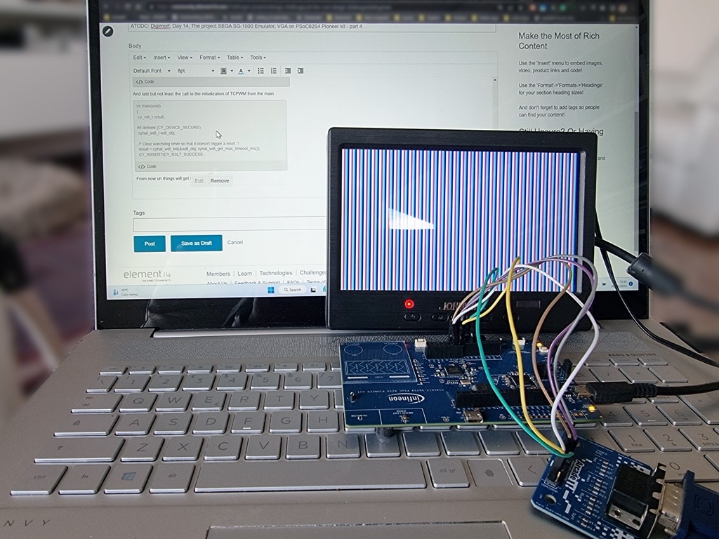
As seen also in this short closeup video.
From now on things will get harder of course. Another counter will rule a DMA transfer from a line buffer or a frame buffer. Hard work to take advantage of the resources of the MCU, but this will free precious system cycles for emulation.
See you in the next part!