element14 Community
element14 Community
    Register Log In
  • Site
  • Search
  • Log In Register
  • Community Hub
    Community Hub
    • What's New on element14
    • Feedback and Support
    • Benefits of Membership
    • Personal Blogs
    • Members Area
    • Achievement Levels
  • Learn
    Learn
    • Ask an Expert
    • eBooks
    • element14 presents
    • Learning Center
    • Tech Spotlight
    • STEM Academy
    • Webinars, Training and Events
    • Learning Groups
  • Technologies
    Technologies
    • 3D Printing
    • FPGA
    • Industrial Automation
    • Internet of Things
    • Power & Energy
    • Sensors
    • Technology Groups
  • Challenges & Projects
    Challenges & Projects
    • Design Challenges
    • element14 presents Projects
    • Project14
    • Arduino Projects
    • Raspberry Pi Projects
    • Project Groups
  • Products
    Products
    • Arduino
    • Avnet & Tria Boards Community
    • Dev Tools
    • Manufacturers
    • Multicomp Pro
    • Product Groups
    • Raspberry Pi
    • RoadTests & Reviews
  • About Us
  • Store
    Store
    • Visit Your Store
    • Choose another store...
      • Europe
      •  Austria (German)
      •  Belgium (Dutch, French)
      •  Bulgaria (Bulgarian)
      •  Czech Republic (Czech)
      •  Denmark (Danish)
      •  Estonia (Estonian)
      •  Finland (Finnish)
      •  France (French)
      •  Germany (German)
      •  Hungary (Hungarian)
      •  Ireland
      •  Israel
      •  Italy (Italian)
      •  Latvia (Latvian)
      •  
      •  Lithuania (Lithuanian)
      •  Netherlands (Dutch)
      •  Norway (Norwegian)
      •  Poland (Polish)
      •  Portugal (Portuguese)
      •  Romania (Romanian)
      •  Russia (Russian)
      •  Slovakia (Slovak)
      •  Slovenia (Slovenian)
      •  Spain (Spanish)
      •  Sweden (Swedish)
      •  Switzerland(German, French)
      •  Turkey (Turkish)
      •  United Kingdom
      • Asia Pacific
      •  Australia
      •  China
      •  Hong Kong
      •  India
      • Japan
      •  Korea (Korean)
      •  Malaysia
      •  New Zealand
      •  Philippines
      •  Singapore
      •  Taiwan
      •  Thailand (Thai)
      • Vietnam
      • Americas
      •  Brazil (Portuguese)
      •  Canada
      •  Mexico (Spanish)
      •  United States
      Can't find the country/region you're looking for? Visit our export site or find a local distributor.
  • Translate
  • Profile
  • Settings
At The Core Design Challenge
  • Challenges & Projects
  • Design Challenges
  • At The Core Design Challenge
  • More
  • Cancel
At The Core Design Challenge
Blog ATCDC: Digimorf, Day 26, The project SEGA SG-1000 Emulator on PSoC62S4 Pioneer kit - part 6
  • Blog
  • Forum
  • Documents
  • Leaderboard
  • Polls
  • Files
  • Members
  • Mentions
  • Sub-Groups
  • Tags
  • More
  • Cancel
  • New
Join At The Core Design Challenge to participate - click to join for free!
  • Share
  • More
  • Cancel
Group Actions
  • Group RSS
  • More
  • Cancel
Engagement
  • Author Author: Digimorf
  • Date Created: 25 Mar 2023 9:50 PM Date Created
  • Views 635 views
  • Likes 7 likes
  • Comments 4 comments
  • infineon
  • PSoCTm︎ 62 MCU
  • CM0+
  • irq
  • dual-core
  • challenge
Related
Recommended

ATCDC: Digimorf, Day 26, The project SEGA SG-1000 Emulator on PSoC62S4 Pioneer kit - part 6

Digimorf
Digimorf
25 Mar 2023
ATCDC: Digimorf, Day 26, The project SEGA SG-1000 Emulator on PSoC62S4 Pioneer kit - part 6

I have been stuck in a problem, I think, in the macros and definitions generated by the project creator wizard. I am not 100% sure, but I have a feeling it's a bug. Let's try to explain what happened and what workaround I adopted.

You all have seen the image shown on my portable VGA monitor. That video driver was running on the CM4 core of a dual-core project, generated by the project wizard of Modus Toolbox. The idea of running that kind of video driver on the CM4 core may be the obvious one, but it's not the best because if we need to implement a simple 3D graphic engine we would like to take advantage of the full core, without the risk of interfering with the video generation. 

So, at that point, we need to generate the video, which is a simple task aided by the hardware through Timers and DMA, on the CM0+. Now, the TCPWM channel that generates the HSync signal uses an IRQ and an ISR to count each pulse as a scanline and drive the VSync at the correct scanline number. The problem is that the TCPWM0 group1 counter4 (alternate function of P9_0 used for VGA HSync) uses the tcpwm_0_interrupts_260_IRQn (enumerator 135).

It's a problem because the core cm0+ doesn't have a direct connection to that system IRQ, but needs to connect to it through a multiplexer that needs to be configured. OK, let's do it.

The structure used to configure this connection is the same that I used for the CM4 core:

/**
* Initialization configuration structure for a single interrupt channel
*/
typedef struct {
#if defined (CY_IP_M7CPUSS)
    uint32_t        intrSrc;        /**< Bit 0-15 indicate system interrupt and bit 16-31 will indicate the CPU IRQ */
#else /* CY_IP_M7CPUSS */
    IRQn_Type       intrSrc;        /**< Interrupt source */
#endif
#if (CY_CPU_CORTEX_M0P) && defined (CY_IP_M4CPUSS)
    cy_en_intr_t    cm0pSrc;        /**< Maps cm0pSrc device interrupt to intrSrc */
#endif /* CY_CPU_CORTEX_M0P */
    uint32_t        intrPriority;   /**< Interrupt priority number (Refer to __NVIC_PRIO_BITS) */
} cy_stc_sysint_t;

So, I need to connect tcpwm_0_interrupts_260_IRQn to a cy_en_intr_t  cm0pSrc, but I can't since the preprocessor condition #if (CY_CPU_CORTEX_M0P) && defined (CY_IP_M4CPUSS) is not met. Even if I am working on the code of the project for the cm0+ core, this field of the structure is not enabled.

I started to reverse engineering the macros, definitions, etc. to find the origin, and where this condition is defined, but no way. No suggestions from Infineon community. So I passed a couple of days in the darkness.

This morning I decided to take a workaround and do it the old-school way. I have found in the registers manual the registers that need to be accessed to configure the multiplexer.

image

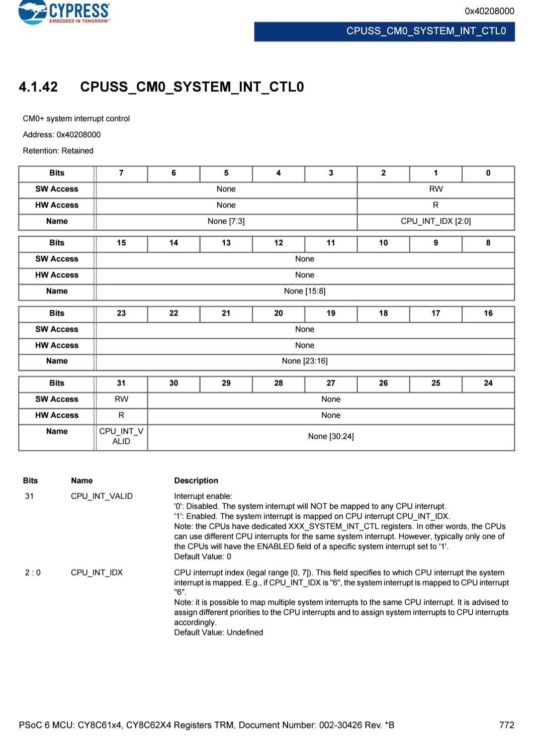
The register CPUSS_CM0_SYSTEM_INT_CTL0 is the first of a sequence of 175 registers that are associated with the system IRQs. It is possible to connect an IRQ to one of the eight connectable IRQs of the CM0+ core.

It's very easy to do it because you could write directly to the register the number of the CM0+ IRQs and activate it.

*((uint32*)(0x40208000+sysirqn)) = 0x80000000 ¦ cm0irqn;

Then you have to assign an ISR to the IRQ channel then enable the IRQ as usual. 

  /* Initialize the interrupt with vector at Interrupt_Handler_Port0() */
  cy_stc_sysint_t HSyncInt_cfg = {
      0,
      0
  };

  uint32_t *intPtr = &((uint32_t*)0x40208000)[tcpwm_0_interrupts_260_IRQn];
  *intPtr = 0x80000000;

  /* Initialize the interrupt service routine (ISR) */
  Cy_SysInt_Init(&HSyncInt_cfg, (cy_israddress)RGB_VGA_Scanline_Start_ISR);

  /* Enable the interrupt */
  NVIC_EnableIRQ(HSyncInt_cfg.intrSrc);

In this case, I connected the system IRQ 130 to the CM0+ IRQ 0, and it worked nicely. The IronMan picture was also shown from the CM0+ core.

Again, this is a workaround but I would like to know if there is something I got wrong generating the dual-core project, or if there is something I have to do with this need.

  • Sign in to reply

Top Comments

  • e14phil
    e14phil over 2 years ago +1
    Hey Digimorf I am going to send this over to our technical contacts at Infineon who have kindly offered to help. Hope that is ok with you! You posts have been fantastic
  • Digimorf
    Digimorf over 2 years ago in reply to ClarkJarvis-Infineon

    Hello Clark,

    thank you for your help. I believed something weird was happening with definitions and indexer, but I wasn't lucky in finding where the inclusion was.

    Anyway, Eclipse IDE is great but sometimes there are bugs in highlighting syntax, etc. Everything works during compilation even if the indexer seems to be confused. But thank you.

    • Cancel
    • Vote Up 0 Vote Down
    • Sign in to reply
    • More
    • Cancel
  • ClarkJarvis-Infineon
    ClarkJarvis-Infineon over 2 years ago

    Digimorf, I believe the initial issue you are dealing with is that the IDE's Context Assist is not picking up the compiler defines / macros correctly.  This happens quite often with ModusToolbox, as it is using a Make based built system and is separate from the IDE (I'm assuming you are using the Eclipse-based IDE).

    The CY_CPU_CORTEX_M0P macro gets set by including the corresponding cmsis core_cm0.h header file.  The Makefile is responsible for including this specific file, but unfortunately that means the IDE is cannot resolve which header file (cm0, cm4, cm7, etc...) is included for context assist features.

    For the CM0 project, the CY_CPU_CORTEX_M0P and CY_IP_M4CPUSS are defined and even though the code in the IDE appears to be compiled out with the #ifdef, it is in fact really there...

    Refer to the code snippet below where I setup a Timer interrupt and mux the peripheral interrupt source to one of the CM0+ IRQ sources.

    /* Initialize and Enable Timer interrupt with the NVIC */
    cy_stc_sysint_t irqCfg_Timer = {
        .intrSrc = NvicMux2_IRQn,
        .cm0pSrc = MyTimer_IRQ,
        .intrPriority = 3
    };
    Cy_SysInt_Init(&irqCfg_Timer, MyTimerISR);
    NVIC_ClearPendingIRQ(irqCfg_Timer.intrSrc);
    NVIC_EnableIRQ(irqCfg_Timer.intrSrc);

    In the code snippet above, I have used the Device Configurator to setup a TCPWM as a Timer, and provided a name of "MyTimer"

    The generated code then creates several additional macros that I'm using in my application.  For this code snippet above, I'm using MyTimer_IRQ that the Device Configurator has mapped to tcpwm_1_interrupts_4_IRQn.

    By specifying the additional .cm0pSrc variable and the .intrSrc variable, the device will map the peripheral interrupt source for the TWPWM Group 1 Instance 4 to the CM0+ NVIC IRQ 2

    Make sure the subsequent NVIC_xxxx commands are then using the NvicMux value (and not the peripheral source).  I've run into that issue in my own projects.

    For additional details here is a good Application Note on PSoC 5 MCU interrupts (link)

    • Cancel
    • Vote Up 0 Vote Down
    • Sign in to reply
    • More
    • Cancel
  • Digimorf
    Digimorf over 2 years ago in reply to e14phil

    Thank you very much! I am glad if this experience can be useful to users and Infineon BlushThumbsup

    • Cancel
    • Vote Up 0 Vote Down
    • Sign in to reply
    • More
    • Cancel
  • e14phil
    e14phil over 2 years ago

    Hey Digimorf I am going to send this over to our technical contacts at Infineon who have kindly offered to help. Hope that is ok with you! Slight smile 
    You posts have been fantastic

    • Cancel
    • Vote Up +1 Vote Down
    • Sign in to reply
    • More
    • Cancel
element14 Community

element14 is the first online community specifically for engineers. Connect with your peers and get expert answers to your questions.

  • Members
  • Learn
  • Technologies
  • Challenges & Projects
  • Products
  • Store
  • About Us
  • Feedback & Support
  • FAQs
  • Terms of Use
  • Privacy Policy
  • Legal and Copyright Notices
  • Sitemap
  • Cookies

An Avnet Company © 2026 Premier Farnell Limited. All Rights Reserved.

Premier Farnell Ltd, registered in England and Wales (no 00876412), registered office: Farnell House, Forge Lane, Leeds LS12 2NE.

ICP 备案号 10220084.

Follow element14

  • X
  • Facebook
  • linkedin
  • YouTube