element14 Community
element14 Community
    Register Log In
  • Site
  • Search
  • Log In Register
  • About Us
  • Community Hub
    Community Hub
    • What's New on element14
    • Feedback and Support
    • Benefits of Membership
    • Personal Blogs
    • Members Area
    • Achievement Levels
  • Learn
    Learn
    • Ask an Expert
    • eBooks
    • element14 presents
    • Learning Center
    • Tech Spotlight
    • STEM Academy
    • Webinars, Training and Events
    • Learning Groups
  • Technologies
    Technologies
    • 3D Printing
    • FPGA
    • Industrial Automation
    • Internet of Things
    • Power & Energy
    • Sensors
    • Technology Groups
  • Challenges & Projects
    Challenges & Projects
    • Design Challenges
    • element14 presents Projects
    • Project14
    • Arduino Projects
    • Raspberry Pi Projects
    • Project Groups
  • Products
    Products
    • Arduino
    • Avnet Boards Community
    • Dev Tools
    • Manufacturers
    • Multicomp Pro
    • Product Groups
    • Raspberry Pi
    • RoadTests & Reviews
  • Store
    Store
    • Visit Your Store
    • Choose another store...
      • Europe
      •  Austria (German)
      •  Belgium (Dutch, French)
      •  Bulgaria (Bulgarian)
      •  Czech Republic (Czech)
      •  Denmark (Danish)
      •  Estonia (Estonian)
      •  Finland (Finnish)
      •  France (French)
      •  Germany (German)
      •  Hungary (Hungarian)
      •  Ireland
      •  Israel
      •  Italy (Italian)
      •  Latvia (Latvian)
      •  
      •  Lithuania (Lithuanian)
      •  Netherlands (Dutch)
      •  Norway (Norwegian)
      •  Poland (Polish)
      •  Portugal (Portuguese)
      •  Romania (Romanian)
      •  Russia (Russian)
      •  Slovakia (Slovak)
      •  Slovenia (Slovenian)
      •  Spain (Spanish)
      •  Sweden (Swedish)
      •  Switzerland(German, French)
      •  Turkey (Turkish)
      •  United Kingdom
      • Asia Pacific
      •  Australia
      •  China
      •  Hong Kong
      •  India
      •  Korea (Korean)
      •  Malaysia
      •  New Zealand
      •  Philippines
      •  Singapore
      •  Taiwan
      •  Thailand (Thai)
      • Americas
      •  Brazil (Portuguese)
      •  Canada
      •  Mexico (Spanish)
      •  United States
      Can't find the country/region you're looking for? Visit our export site or find a local distributor.
  • Translate
  • Profile
  • Settings
At The Core Design Challenge
  • Challenges & Projects
  • Design Challenges
  • At The Core Design Challenge
  • More
  • Cancel
At The Core Design Challenge
Forum CY8C62 DMA from buffer to GPIO P10_0..2
  • Blog
  • Forum
  • Documents
  • Leaderboard
  • Polls
  • Files
  • Members
  • Mentions
  • Sub-Groups
  • Tags
  • More
  • Cancel
  • New
Join At The Core Design Challenge to participate - click to join for free!
Actions
  • Share
  • More
  • Cancel
Forum Thread Details
  • State Suggested Answer
  • Replies 8 replies
  • Answers 1 answer
  • Subscribers 50 subscribers
  • Views 1842 views
  • Users 0 members are here
  • design challenge
  • dmac
  • gpio
  • psoc6
  • at the core
Related

CY8C62 DMA from buffer to GPIO P10_0..2

Digimorf
Digimorf over 2 years ago

Hello,

I am working on the configuration of a DMAC channel for streaming data bytes from a buffer to the GPIO port 10, using only GPIOs from 0 to 2. I think I am missing something but I really can't make it work.

Since I am learning for now I am triggering the DMA by simply enabling the block, next I will trigger it with a CC0 of a counter. But, let's see what I got so far.

I have started an "Empty Project" from the getting started section. Then in the "Device Configurator" I simply set the DMAC channel 0 for a transfer of 1 byte.

/* NOTE: This is a preview only. It combines elements of the
 * cycfg_dmas.c and cycfg_dmas.h files located in the folder
 * C:/Users/Francesco/mtw/Empty_App_1/bsps/TARGET_APP_CY8CKIT-062S4/config/GeneratedSource.
 */

#include "cy_dmac.h"
#if defined (CY_USING_HAL)
    #include "cyhal_hwmgr.h"
#endif //defined (CY_USING_HAL)

#define cpuss_0_dmac_0_chan_0_HW DMAC
#define cpuss_0_dmac_0_chan_0_CHANNEL 0U
#define cpuss_0_dmac_0_chan_0_IRQ cpuss_interrupts_dmac_0_IRQn

cy_stc_dmac_descriptor_config_t cpuss_0_dmac_0_chan_0_Descriptor_0_config = 
{
    .retrigger = CY_DMAC_RETRIG_IM,
    .interruptType = CY_DMAC_1ELEMENT,
    .triggerOutType = CY_DMAC_1ELEMENT,
    .channelState = CY_DMAC_CHANNEL_ENABLED,
    .triggerInType = CY_DMAC_1ELEMENT,
    .dataPrefetch = false,
    .dataSize = CY_DMAC_WORD,
    .srcTransferSize = CY_DMAC_TRANSFER_SIZE_WORD,
    .dstTransferSize = CY_DMAC_TRANSFER_SIZE_WORD,
    .descriptorType = CY_DMAC_SINGLE_TRANSFER,
    .srcAddress = NULL,
    .dstAddress = NULL,
    .srcXincrement = 0,
    .dstXincrement = 0,
    .xCount = 1,
    .srcYincrement = 1,
    .dstYincrement = 1,
    .yCount = 1,
    .nextDescriptor = NULL,
};
cy_stc_dmac_descriptor_t cpuss_0_dmac_0_chan_0_Descriptor_0 = 
{
    .ctl = 0UL,
    .src = 0UL,
    .dst = 0UL,
    .xSize = 0UL,
    .xIncr = 0UL,
    .ySize = 0UL,
    .yIncr = 0UL,
    .nextPtr = 0UL,
};
cy_stc_dmac_channel_config_t cpuss_0_dmac_0_chan_0_channelConfig = 
{
    .descriptor = &cpuss_0_dmac_0_chan_0_Descriptor_0,
    .priority = 3,
    .enable = false,
    .bufferable = false,
};
#if defined (CY_USING_HAL)
    const cyhal_resource_inst_t cpuss_0_dmac_0_chan_0_obj = 
    {
        .type = CYHAL_RSC_DMA,
        .block_num = 2U,
        .channel_num = cpuss_0_dmac_0_chan_0_CHANNEL,
    };
#endif //defined (CY_USING_HAL)


void reserve_cycfg_dmas(void)
{
#if defined (CY_USING_HAL)
    cyhal_hwmgr_reserve(&cpuss_0_dmac_0_chan_0_obj);
#endif //defined (CY_USING_HAL)
}

The three GPIOs P10_0..2 are configured as:

const cy_stc_gpio_pin_config_t CYBSP_A0_config = 
{
    .outVal = 0,
    .driveMode = CY_GPIO_DM_STRONG_IN_OFF,
    .hsiom = CYBSP_A0_HSIOM,
    .intEdge = CY_GPIO_INTR_DISABLE,
    .intMask = 0UL,
    .vtrip = CY_GPIO_VTRIP_CMOS,
    .slewRate = CY_GPIO_SLEW_FAST,
    .driveSel = CY_GPIO_DRIVE_1_2,
    .vregEn = 0UL,
    .ibufMode = 0UL,
    .vtripSel = 0UL,
    .vrefSel = 0UL,
    .vohSel = 0UL,
};

Then in the main.c I set the destination and source:

#include "cyhal.h"
#include "cybsp.h"

#define scanline_dma_HW             cpuss_0_dmac_0_chan_0_HW
#define scanline_dma_descriptor     cpuss_0_dmac_0_chan_0_Descriptor_0
#define scanline_dma_descriptor_cfg cpuss_0_dmac_0_chan_0_Descriptor_0_config
#define scanline_dma_CH             cpuss_0_dmac_0_chan_0_CHANNEL
#define scanline_dma_CH_cfg         cpuss_0_dmac_0_chan_0_channelConfig

uint32_t pix = 0x5;
GPIO_PRT_Type* scanline_rgb_port = GPIO_PRT10;


int main(void)
{
    cy_rslt_t result;

#if defined (CY_DEVICE_SECURE)
    cyhal_wdt_t wdt_obj;

    /* Clear watchdog timer so that it doesn't trigger a reset */
    result = cyhal_wdt_init(&wdt_obj, cyhal_wdt_get_max_timeout_ms());
    CY_ASSERT(CY_RSLT_SUCCESS == result);
    cyhal_wdt_free(&wdt_obj);
#endif

    /* Initialize the device and board peripherals */
    result = cybsp_init();

    /* Board init failed. Stop program execution */
    if (result != CY_RSLT_SUCCESS)
    {
        CY_ASSERT(0);
    }

    /* Enable global interrupts */
    __enable_irq();

    Cy_DMAC_Descriptor_Init(&scanline_dma_descriptor,
                            &scanline_dma_descriptor_cfg);

    Cy_DMAC_Descriptor_SetSrcAddress(&scanline_dma_descriptor,
                                     (void*)&pix);

    Cy_DMAC_Descriptor_SetDstAddress(&scanline_dma_descriptor,
                                     (void*)(scanline_rgb_port->OUT));

    Cy_DMAC_Channel_Init(scanline_dma_HW,
                         scanline_dma_CH,
                         &scanline_dma_CH_cfg);

    Cy_DMAC_Channel_SetDescriptor(scanline_dma_HW,
                                  scanline_dma_CH,
                                  &scanline_dma_descriptor);

    Cy_DMAC_Channel_Enable(scanline_dma_HW,
                          scanline_dma_CH);

    Cy_DMAC_Enable(scanline_dma_HW);

    for (;;)
    {

    }
}

My Logic Analyzer should show signals 0 and 2 pulsing from low to high but nothing happens, I can't understand if the transfer doesn't start, or if the GPIO port is not correct for output.

I haven't been lucky in finding an example of the use of DMA on GPIOs, so I am asking here Slight smile

Thank you.

  • Sign in to reply
  • Cancel

Top Replies

  • Digimorf
    Digimorf over 2 years ago +2
    Digimorf said: In the Trigger multiplexer diagram, I saw that the CPUSS.Zero should be a software trigger connected to the DMAC block, but I wasn't able to find what this "Zero" means in the CPU SubSystem…
  • misaz
    misaz over 2 years ago in reply to Digimorf +1
    In my app I use DW instead of DMAC and DW works. I will write several blogs about it. How do you trigger DMA(C) transfer?
  • misaz
    misaz over 2 years ago in reply to Digimorf +1
    Your DMA transfer most probably failed because of ilegal bus access. I have faced similar problem. Issue is that GPIO OUT register prohibits byte (8-bit) and word (16-bit) AXI access and allows only…
  • Digimorf
    0 Digimorf over 2 years ago

    I forgot, If I send data to GPIO port by hand the output works, so I believe the problem is not in the address of the port.

    scanline_rgb_port->OUT = pix;

    • Cancel
    • Vote Up 0 Vote Down
    • Sign in to reply
    • Verify Answer
    • Cancel
  • Digimorf
    0 Digimorf over 2 years ago

    Definitely, there is something wrong with DMA. Currently, I did a simple test with a memory-to-memory transfer, like the one shown in the online PDL documentation, but it doesn't start at all. So there's something I am missing.

    • Cancel
    • Vote Up 0 Vote Down
    • Sign in to reply
    • Verify Answer
    • Cancel
  • misaz
    0 misaz over 2 years ago in reply to Digimorf

    In my app I use DW instead of DMAC and DW works. I will write several blogs about it. How do you trigger DMA(C) transfer?

    • Cancel
    • Vote Up +1 Vote Down
    • Sign in to reply
    • Verify Answer
    • Cancel
  • Digimorf
    0 Digimorf over 2 years ago in reply to misaz

    I am working on a Dual-core project, in the CM0+ part.

        Cy_DMAC_Descriptor_Init(&scanline_dma_descriptor,
                                &scanline_dma_descriptor_cfg);
    
        Cy_DMAC_Descriptor_SetSrcAddress(&scanline_dma_descriptor,
                                         (void*)(&src[0]));
    
        Cy_DMAC_Descriptor_SetDstAddress(&scanline_dma_descriptor,
                                         (void*)(&dst[0]));
    
        Cy_DMAC_Channel_Init(scanline_dma_HW,
                             scanline_dma_CH,
                             &scanline_dma_CH_cfg);
    
        Cy_DMAC_Channel_SetDescriptor(scanline_dma_HW,
                                      scanline_dma_CH,
                                      &scanline_dma_descriptor);
    
        Cy_DMAC_Channel_Enable(scanline_dma_HW,
                              scanline_dma_CH);
    
        Cy_DMAC_Enable(scanline_dma_HW);

    #define scanline_dma_HW             cpuss_0_dmac_0_chan_0_HW
    #define scanline_dma_descriptor     cpuss_0_dmac_0_chan_0_Descriptor_0
    #define scanline_dma_descriptor_cfg cpuss_0_dmac_0_chan_0_Descriptor_0_config
    #define scanline_dma_CH             cpuss_0_dmac_0_chan_0_CHANNEL
    #define scanline_dma_CH_cfg         cpuss_0_dmac_0_chan_0_channelConfig
    

    Basically here, for test purposes, I am trying to perform a memory-to-memory copy. So I only need a simple software trigger.

    The two buffers are simple arrays of chars:

    char src[32];
    char dst[32];

    While the descriptor has been defined in Device Configurator:

    #define cpuss_0_dmac_0_chan_0_HW DMAC
    #define cpuss_0_dmac_0_chan_0_CHANNEL 0U
    #define cpuss_0_dmac_0_chan_0_IRQ cpuss_interrupts_dmac_0_IRQn
    
    cy_stc_dmac_descriptor_config_t cpuss_0_dmac_0_chan_0_Descriptor_0_config = 
    {
        .retrigger = CY_DMAC_RETRIG_IM,
        .interruptType = CY_DMAC_DESCR,
        .triggerOutType = CY_DMAC_DESCR,
        .channelState = CY_DMAC_CHANNEL_ENABLED,
        .triggerInType = CY_DMAC_DESCR,
        .dataPrefetch = false,
        .dataSize = CY_DMAC_BYTE,
        .srcTransferSize = CY_DMAC_TRANSFER_SIZE_DATA,
        .dstTransferSize = CY_DMAC_TRANSFER_SIZE_DATA,
        .descriptorType = CY_DMAC_MEMORY_COPY,
        .srcAddress = NULL,
        .dstAddress = NULL,
        .srcXincrement = 1,
        .dstXincrement = 1,
        .xCount = 16,
        .srcYincrement = 1,
        .dstYincrement = 1,
        .yCount = 1,
        .nextDescriptor = NULL,
    };
    cy_stc_dmac_descriptor_t cpuss_0_dmac_0_chan_0_Descriptor_0 = 
    {
        .ctl = 0UL,
        .src = 0UL,
        .dst = 0UL,
        .xSize = 0UL,
        .xIncr = 0UL,
        .ySize = 0UL,
        .yIncr = 0UL,
        .nextPtr = 0UL,
    };
    cy_stc_dmac_channel_config_t cpuss_0_dmac_0_chan_0_channelConfig = 
    {
        .descriptor = &cpuss_0_dmac_0_chan_0_Descriptor_0,
        .priority = 3,
        .enable = false,
        .bufferable = false,
    };
         

    In the few examples I have found in Application Notes, and PDL documentation, the DMA transfer should start as soon as a "Cy_DMAC_Enable" it's invoked. Maybe I am wrong...

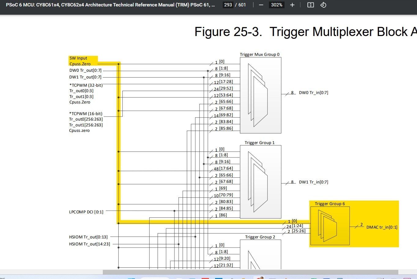
    In the Trigger multiplexer diagram, I saw that the CPUSS.Zero should be a software trigger connected to the DMAC block, but I wasn't able to find what this "Zero" means in the CPU SubSystem. 

    • Cancel
    • Vote Up 0 Vote Down
    • Sign in to reply
    • Verify Answer
    • Cancel
  • Digimorf
    0 Digimorf over 2 years ago
    Digimorf said:
    In the Trigger multiplexer diagram, I saw that the CPUSS.Zero should be a software trigger connected to the DMAC block, but I wasn't able to find what this "Zero" means in the CPU SubSystem. 

    Actually, the solution was there in front of me.

    The Multiplexer Block Diagram shows the interconnections possible between the triggers of the peripherals. Here the white rabbit hole gets deeper because all these connections are fully programmable. This is a great surprise, another "like" for this microcontroller!

    I discovered that the PDL offers the TrigMux (Trigger Multiplexer) driver, which offers the function to interconnect triggers, and FINALLY how to fire a software trigger on a specific line! That is what I wanted, damn three days of tests, research, and readings.

    TrigMux PDL driver

    The function needed to start the DMAC, channel 0 is:

    if (CY_TRIGMUX_SUCCESS != Cy_TrigMux_SwTrigger(TRIG_OUT_MUX_6_MDMA_TR_IN0, CY_TRIGGER_TWO_CYCLES))

    From the file 

    %user%\mtw\mtb_shared\mtb-pdl-cat1\release-v3.2.0\devices\COMPONENT_CAT1A\include\psoc6_04_config.h

    you can find all the enumerators for the interconnections where I got "TRIG_OUT_MUX_6_MDMA_TR_IN0" from. In this case, I have found this enumerator:

    /* Trigger Output Group 6 - MDMA trigger multiplexer */
    typedef enum
    {
        TRIG_OUT_MUX_6_MDMA_TR_IN0      = 0x40000600u, /* cpuss.dmac_tr_in[0] */
        TRIG_OUT_MUX_6_MDMA_TR_IN1      = 0x40000601u /* cpuss.dmac_tr_in[1] */
    } en_trig_output_mdma_t;

    If you look at the trigger multiplexer block diagram you can find the DMAC in group 6, and the MUX has three kinds of triggers. The first is exactly the CPUSS.Zero, and in my case, I am using channel 0.

    dmac_trigger

    There you go, after enabling the DMAC you have to fire the software trigger and the DMA starts.

    To recap here's the definition from Device Configurator:

    #define cpuss_0_dmac_0_chan_0_HW DMAC
    #define cpuss_0_dmac_0_chan_0_CHANNEL 0U
    #define cpuss_0_dmac_0_chan_0_IRQ cpuss_interrupts_dmac_0_IRQn
    
    cy_stc_dmac_descriptor_config_t cpuss_0_dmac_0_chan_0_Descriptor_0_config = 
    {
        .retrigger = CY_DMAC_WAIT_FOR_REACT,
        .interruptType = CY_DMAC_1ELEMENT,
        .triggerOutType = CY_DMAC_1ELEMENT,
        .channelState = CY_DMAC_CHANNEL_ENABLED,
        .triggerInType = CY_DMAC_1ELEMENT,
        .dataPrefetch = false,
        .dataSize = CY_DMAC_BYTE,
        .srcTransferSize = CY_DMAC_TRANSFER_SIZE_DATA,
        .dstTransferSize = CY_DMAC_TRANSFER_SIZE_DATA,
        .descriptorType = CY_DMAC_MEMORY_COPY,
        .srcAddress = NULL,
        .dstAddress = NULL,
        .srcXincrement = 1,
        .dstXincrement = 1,
        .xCount = 16,
        .srcYincrement = 1,
        .dstYincrement = 1,
        .yCount = 1,
        .nextDescriptor = NULL,
    };
    cy_stc_dmac_descriptor_t cpuss_0_dmac_0_chan_0_Descriptor_0 = 
    {
        .ctl = 0UL,
        .src = 0UL,
        .dst = 0UL,
        .xSize = 0UL,
        .xIncr = 0UL,
        .ySize = 0UL,
        .yIncr = 0UL,
        .nextPtr = 0UL,
    };
    cy_stc_dmac_channel_config_t cpuss_0_dmac_0_chan_0_channelConfig = 
    {
        .descriptor = &cpuss_0_dmac_0_chan_0_Descriptor_0,
        .priority = 3,
        .enable = false,
        .bufferable = false,
    };

    And the code:

        #define scanline_dma_HW             cpuss_0_dmac_0_chan_0_HW
        #define scanline_dma_descriptor     cpuss_0_dmac_0_chan_0_Descriptor_0
        #define scanline_dma_descriptor_cfg cpuss_0_dmac_0_chan_0_Descriptor_0_config
        #define scanline_dma_CH             cpuss_0_dmac_0_chan_0_CHANNEL
        #define scanline_dma_CH_cfg         cpuss_0_dmac_0_chan_0_channelConfig
        
        char src[32];
        char dst[32];
        
        Cy_DMAC_Descriptor_Init(&scanline_dma_descriptor, &scanline_dma_descriptor_cfg);
    
        Cy_DMAC_Descriptor_SetSrcAddress(&scanline_dma_descriptor, (&src[0]));
    
        Cy_DMAC_Descriptor_SetDstAddress(&scanline_dma_descriptor, (&dst[0]));
    
        Cy_DMAC_Channel_Init(scanline_dma_HW, scanline_dma_CH, &scanline_dma_CH_cfg);
    
        Cy_DMAC_Channel_SetDescriptor(scanline_dma_HW, scanline_dma_CH, &scanline_dma_descriptor);
    
        Cy_DMAC_Channel_Enable(scanline_dma_HW, scanline_dma_CH);
    
        Cy_DMAC_Enable(scanline_dma_HW);
    
        if (CY_TRIGMUX_SUCCESS != Cy_TrigMux_SwTrigger(TRIG_OUT_MUX_6_MDMA_TR_IN0, CY_TRIGGER_TWO_CYCLES))

    • Cancel
    • Vote Up +2 Vote Down
    • Sign in to reply
    • Verify Answer
    • Cancel
  • Digimorf
    0 Digimorf over 2 years ago

    I have partially solved the problem, so if I need to create a fast copy width Dma I know what to do, but actually it seems not working when I address the destination of DMA to GPIO_PRT10->OUT.

    -mumble mumble - 

    • Cancel
    • Vote Up 0 Vote Down
    • Sign in to reply
    • Verify Answer
    • Cancel
  • misaz
    0 misaz over 2 years ago in reply to Digimorf

    Your DMA transfer most probably failed because of ilegal bus access.

    I have faced similar problem. Issue is that GPIO OUT register prohibits byte (8-bit) and word (16-bit) AXI access and allows only double word (32-bit) access like most of PSoC6 registers do. I do not know about DMAC but DW cant do transformation of data and I have to use array of uint32_t with 3 bytes unsed instead of array of uint8_t.

    • Cancel
    • Vote Up +1 Vote Down
    • Sign in to reply
    • Verify Answer
    • Cancel
  • Digimorf
    0 Digimorf over 2 years ago

    FINALLY!

    Actually, the code works, what is wrong is the GPIO output port. I assigned it in the wrong way.

    // WRONG
    // GPIO_PRT_Type* scanline_rgb_port = GPIO_PRT10;
    
    // CORRECT
    uint8_t *scanline_rgb_port = (uint8_t *)(&GPIO_PRT10->OUT);
    

    And in the setup of the DMAC descriptor the destination address:

      Cy_DMAC_Descriptor_SetDstAddress(&scanline_pixel_dma_descriptor, (uint8_t*)(scanline_rgb_port));
      

    • Cancel
    • Vote Up +1 Vote Down
    • Sign in to reply
    • Verify Answer
    • Reject Answer
    • Cancel
element14 Community

element14 is the first online community specifically for engineers. Connect with your peers and get expert answers to your questions.

  • Members
  • Learn
  • Technologies
  • Challenges & Projects
  • Products
  • Store
  • About Us
  • Feedback & Support
  • FAQs
  • Terms of Use
  • Privacy Policy
  • Legal and Copyright Notices
  • Sitemap
  • Cookies

An Avnet Company © 2025 Premier Farnell Limited. All Rights Reserved.

Premier Farnell Ltd, registered in England and Wales (no 00876412), registered office: Farnell House, Forge Lane, Leeds LS12 2NE.

ICP 备案号 10220084.

Follow element14

  • X
  • Facebook
  • linkedin
  • YouTube