


I’ve been having a bit of good fortune this week so thought to crack on while the going is good.
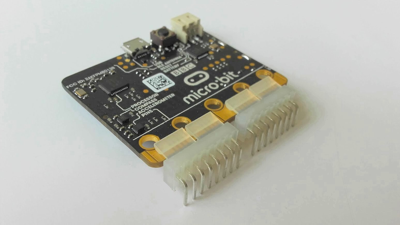
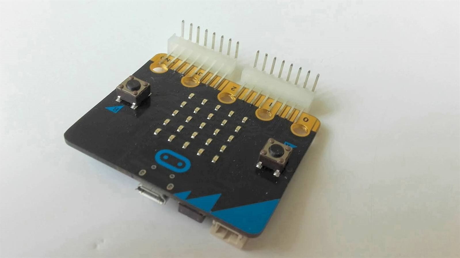
It turned out that the substitute product I ordered because of a stock out with my original choice was way better than I ever imagined. It locks on tightly to the micro:bit and makes connecting external sensors and peripherals during developing and testing phase so much easier.
| {gallery:autoplay=false} My Gallery Title |
|---|
|
|
It was now time to play with my Micro:bits
As we all know it is customary with any new MCU dev board to start with uploading a simple blink up project. However, in my case this did not start off very well. I discovered that a previous MCU USB driver install, which went wrong at the time, has come back to bite me. So, when I connect my micro:bits to my PC via USB cable, I do not get the virtual folder. This is rather essential as you need it to dump your compiled hex file.
So out went MBED and the simpler Microsoft blocks editor, which I had planned to start with – as why over complicate things.
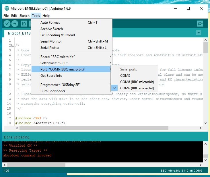
This left me with only one option, which was to figure out how to use the Arduino IDE to develop my application and flash my micro:bit devices. Thankfully, I quickly learnt that Adafruit had a fantastic tutorial that guides you through the process. This can be found here: https://learn.adafruit.com/use-micro-bit-with-arduino
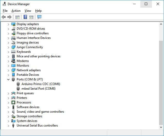
Then, I solved my problem by downloading the mbed driver – not quite sure why this worked for me as I have Windows 10 but it did. This at least provided my Arduino IDE the correct port to flash the firmware.
As you can see from the following images there are 2 serial ports. It is worth noting for others that one is used for flashing and one is used for the serial monitor.
| {gallery:autoplay=false} My Gallery Title |
|---|
|
|
Then, to get to use the Arduino IDE for microbits you need to go to Board Manager and install the files. This is achieved by adding the right URL in preferences, as follows:
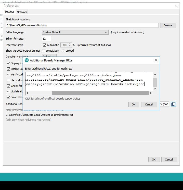
Then, as per the Adafruit guide you need to add the correct board files by searching for “nRF5 Boards” as follows:

Source: Adafruit Learn - Micro:bit with Arduino
Then following through the rest of the setup instructions, I was ready to try their “hello world” blink demo code.
The next stage was to get hold of the Adafruit libraries. I used Library Manager for this.
I was now ready to experiment. As someone who is very familiar with Arduino/Genuino 101 and associated libraries, I found the BLE side very straightforward as it follows similar methodologies in another library (i.e. the BLE peripheral library).
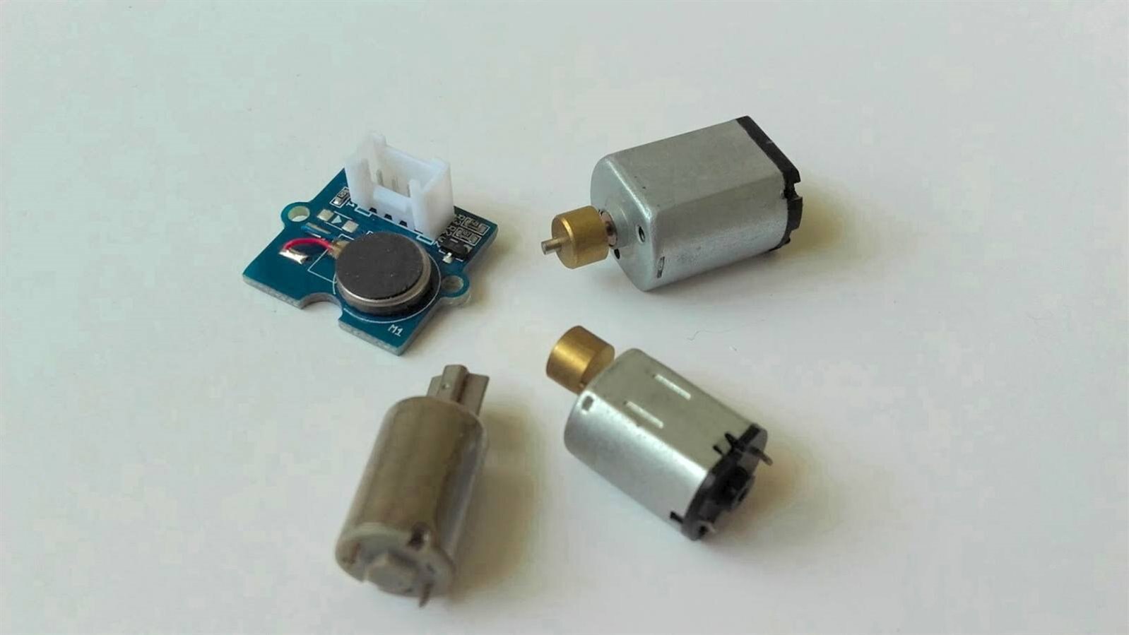
And here is my result. I was able to create a short fun demo, which also tests a small SeeedStudio Grove vibration motor I had ordered – this is something I plan to use for my application.
And here is the code for this demo:
/* @file Microbit_E14demo01
 || @version 1.0
 || @created 18 May 2018
 || @author C. Gerrish (bigG)
 || @project Element 14 Bluetooth Unleashed Design Challenge
 || @licensed under the MIT license.
 ||
 || @description
 || | Handles BLE UART communication from an App
 || | Listens for key messages and responds with
 || | LED matrix message or trigger GPIO output pin 19 to go HIGH
 || #
 */
/*
 * Code is based on the Serial Port over BLE example
 * Creates a UART service compatible with Nordic's *nRF Toolbox* and Adafruit's *Bluefruit LE* iOS/Android apps.
 * Also based on the matrixdemo example
 *
 * Libarary examples copyright (c) Sandeep Mistry. All rights reserved.
 * Licensed under the MIT license. See LICENSE file in the project root for full license information.
 * BLESerial class implements same protocols as Arduino's built-in Serial class and can be used as it's wireless
 * replacement. Data transfers are routed through a BLE service with TX and RX characteristics. To make the
 * service discoverable all UUIDs are NUS (Nordic UART Service) compatible.
 *
 * Please note that TX and RX characteristics use Notify and WriteWithoutResponse, so there's no guarantee
 * that the data will make it to the other end. However, under normal circumstances and reasonable signal
 * strengths everything works well.
 */

#include
#include <adafruit_gfx.h>
#include


#include <adafruit_microbit.h>


#define pinVIBMOT       19          // pin 19 drives vibration motor


const uint8_t
  smile_bmp[] =
  { B00000,
    B01010,
    B00000,
    B10001,
    B01110, };


unsigned long
  t_matrix = 0L,
  t_recvd = 0L;


String bleRecvd = "";


bool BLEconnected = false;


Adafruit_Microbit microbit;


void setup() {
  pinMode(pinVIBMOT, OUTPUT);
  digitalWrite(pinVIBMOT, LOW);

  Serial.begin(115200);


  Serial.println("Microbit is Bluetooth Unleashed ready!");

  // add a custom name
  microbit.BTLESerial.setLocalName("E14demo");
  delay(100);

  // Start BLE advertising etc.
  microbit.BTLESerial.begin();


  // Now start LED matrix driver
  microbit.matrix.begin();
 }


void loop() {
  if (t_recvd) {
    if ((millis() - t_recvd) > 900) {
      Serial.println("");
      bleRecvd.trim();
      if (bleRecvd.length() > 0) {
        bleRecvd.toUpperCase();
        if (bleRecvd.startsWith("E14")) {

            if (bleRecvd.endsWith("!")) {
              Serial.println("trigger GPIO pin 19");
              digitalWrite(pinVIBMOT, HIGH);
            }

            microbit.matrix.clear();
            // draw a heart
            microbit.matrix.show(microbit.matrix.HEART);
            delay(600);
            // scroll some text the 'easy' way
            microbit.matrix.print("'s BLE! ");
            Serial.println(bleRecvd);

            if (bleRecvd.endsWith("!")) digitalWrite(pinVIBMOT, LOW);

        }
        else {
            microbit.matrix.clear();
            // draw a yes tick
            microbit.matrix.drawRect(0,0, 5, 5, LED_ON); // top left corner @ (0,0), 5 by 5 pixels size
            delay(600);
            microbit.matrix.show(microbit.matrix.YES);
            Serial.println(bleRecvd);
            delay(600);
            microbit.matrix.clear();
        }
      }
      bleRecvd = "";
      t_recvd = 0;
    }
  }


  if (microbit.BTLESerial) {              // triggered when BLE connected
    if (!BLEconnected) {
      // draw a custom made bitmap face
      microbit.matrix.show(smile_bmp);
      BLEconnected = true;
      t_matrix = millis();
    }
    byte b = 0;
    if ((b = microbit.BTLESerial.read()) > 0) {
      if (b < 128) {
        if (!t_recvd) t_recvd = millis();
        bleRecvd += char(b);
      }
    }
  }
  else {                                // no longer connected
    if (BLEconnected) {
      // draw a no cross
      microbit.matrix.show(microbit.matrix.NO);
      BLEconnected = false;
      t_matrix = millis();
    }
  }


  if (t_matrix) {
    if ((millis() - t_matrix) > 3000) {
      microbit.matrix.clear();
      t_matrix = 0;
    }
  }
}
Next steps with my Micro:bits
Besides the actual Micro:bit firmware development for my project, the only hardware design required is attaching a suitable vibration motor inside the enclosure. It will either be the new Grove vibration motor I had ordered or it will be one of these vibration motors I have lying around from Precision Microdrives (UK) Ltd.
Top Comments
-

genebren
-
Cancel
-
Vote Up
+2
Vote Down
-
-
Sign in to reply
-
More
-
Cancel
-

BigG
in reply to genebren
-
Cancel
-
Vote Up
+1
Vote Down
-
-
Sign in to reply
-
More
-
Cancel
Comment-

BigG
in reply to genebren
-
Cancel
-
Vote Up
+1
Vote Down
-
-
Sign in to reply
-
More
-
Cancel
Children