


Building The Project
Building this project is divided into three sections.
1) Hardware
2) Software
Now let's look into detail each of the section.
HARDWARE
Now let's look into the first section, which is the hardware section. In this section, we shall see the hardware required to build this project. Mainly there are three main components used as listed below:
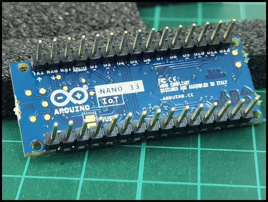
1) Arduino Nano 33 IOT
2) Sharp's GP2Y1010AU0F
3) 1.44' SPI 128*128 TFT Display
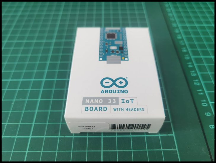
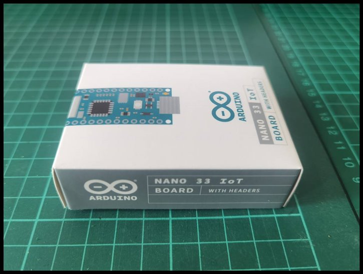
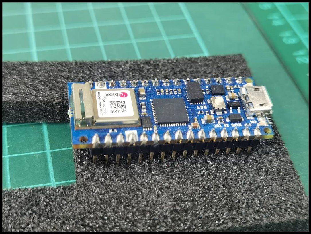
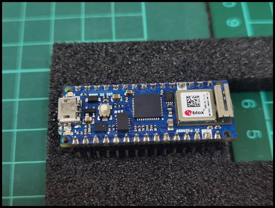
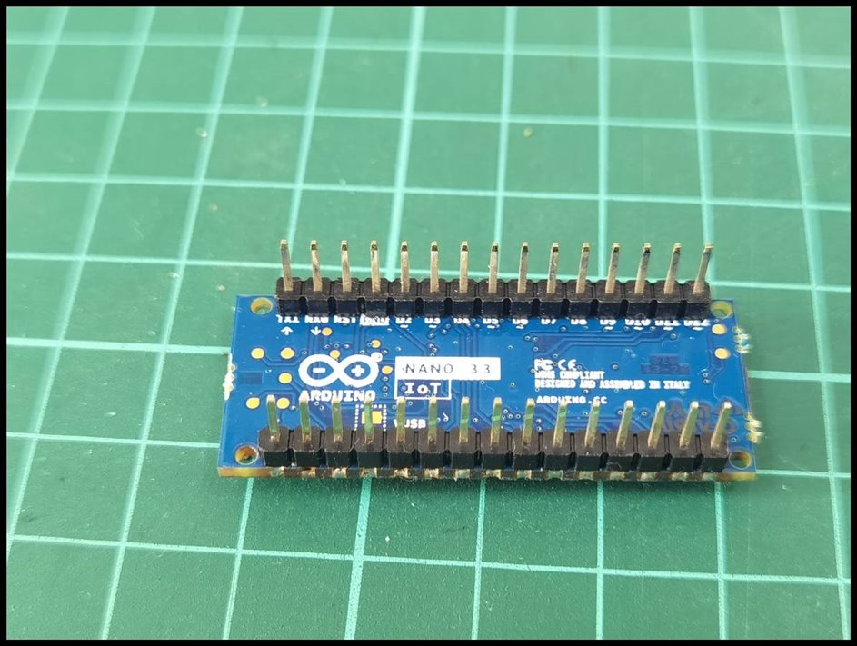
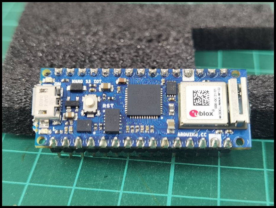
Now let's look into the detail of each of the component. The first component that we would like to look at in detail is the Arduino Nano 33 IOT. Below are some pictures of it.
While going through the pinout and functions of the Arduino nano 33 IoT, I thought of comparing it to the classic Arduino nano.
| CLASSIC ARDUINO NANO | ARDUINO NANO 33 IOT |
|---|---|
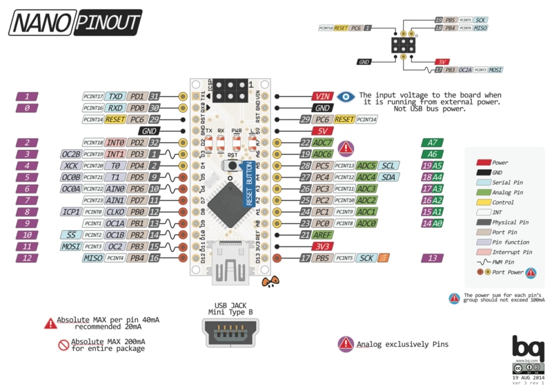 |  |
By comparing both the pinout, the function of each of the pins are almost the same with some improvement on the Arduino Nano 33 IoT board. One of the obvious improvement on the Arduino Nano 33 IoT is the number of PWM pin. In the classic Arduino nano, it has 6 PWM pin and whereas in Arduino Nano 33 IoT has 8 PWM output. The other things that are obvious are the microcontroller used in both the board are different as well.
| Header 1 | Header 2 |
|---|---|
 |  |
 |  |
 |  |
 |  |
So, that's about the Arduino Nano 33 IoT. Now let's move on to the
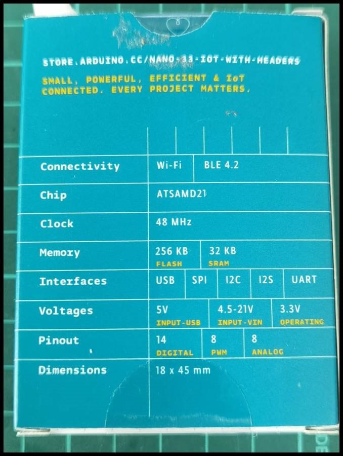
The main controller or the brain of this project is the Arduino Nano 33 IOT. All the processing of the data is done here. Here I share the unboxing video of the board as well.
And the next hardware is the dust sensor. For this project, we decided to use Sharp's GP2Y1010AU0F.
| Header 1 | Header 2 |
|---|---|
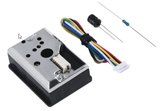 | 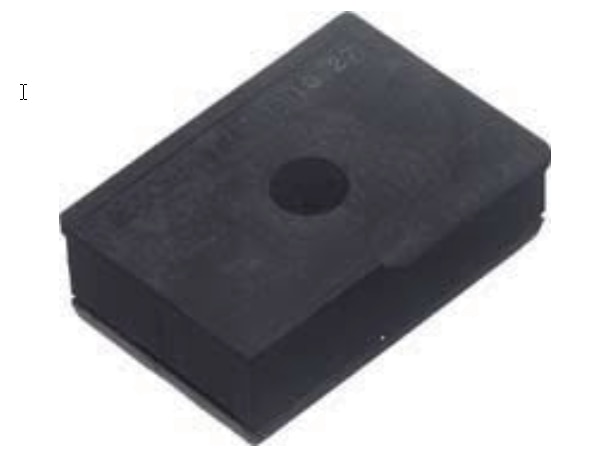 |
The above picture shows the front and rear view of the sensor. And the below figure shows the outline dimension and the internal schematic of the sensor.
| Outline Dimensions | Internal schematic |
|---|---|
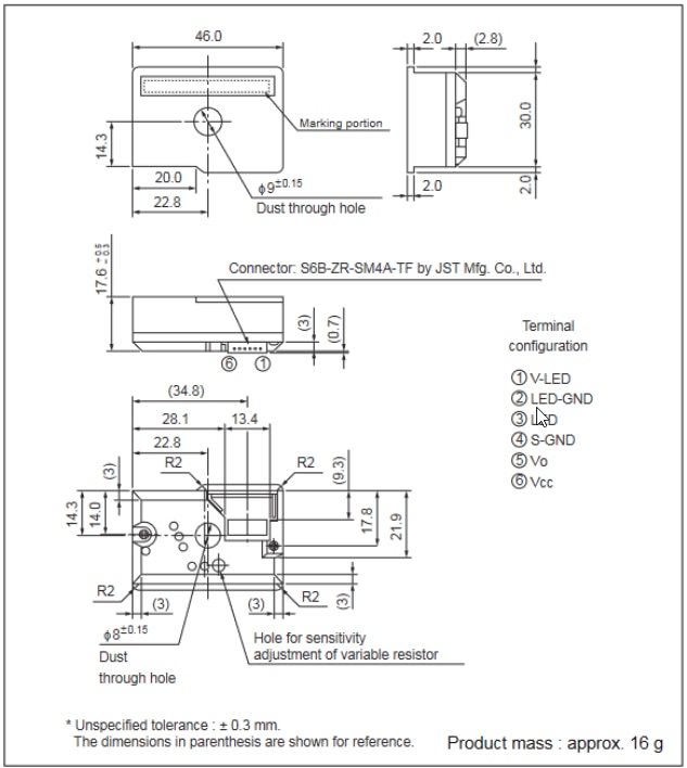 | 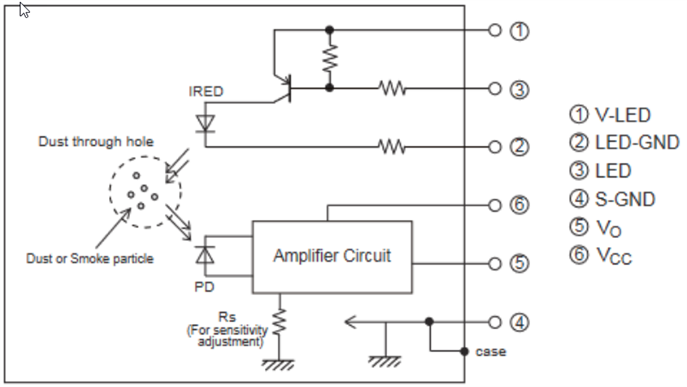 |
The datasheet of this sensor can be downloaded from https://www.sparkfun.com/datasheets/Sensors/gp2y1010au_e.pdf. And below is listed the feature of this sensor
1. Compact, thin package (46.0 × 30.0 × 17.6 mm)
2. Low consumption current (Icc: MAX. 20 mA)
3. The presence of dust can be detected by the photometry of only one pulse
4. Enable to distinguish smoke from house dust
5. Lead-free and RoHS directive compliant
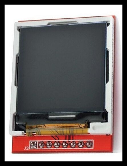
The next component which we would like to see is the 1.44' SPI 128*128 TFT Display. This display is used to display the value of the sensor also to display other useful information. The image below shows the
| Header 1 |
|---|
 |
Basically, these 3 are the main components that are required to complete this project. The rest are the miscellaneous components.
Since the pinout of the Arduino Nano and Arduino Nano 33 IoT are almost identical, I have decided to use the PCB board which I have developed previously. The image below is the board picture.
| Header 1 | Header 2 |
|---|---|
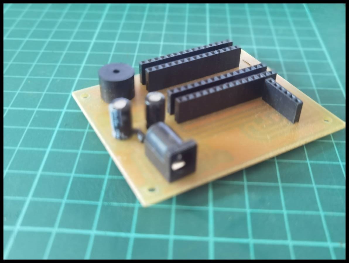 | 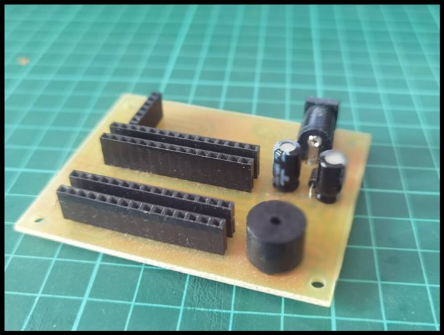 |
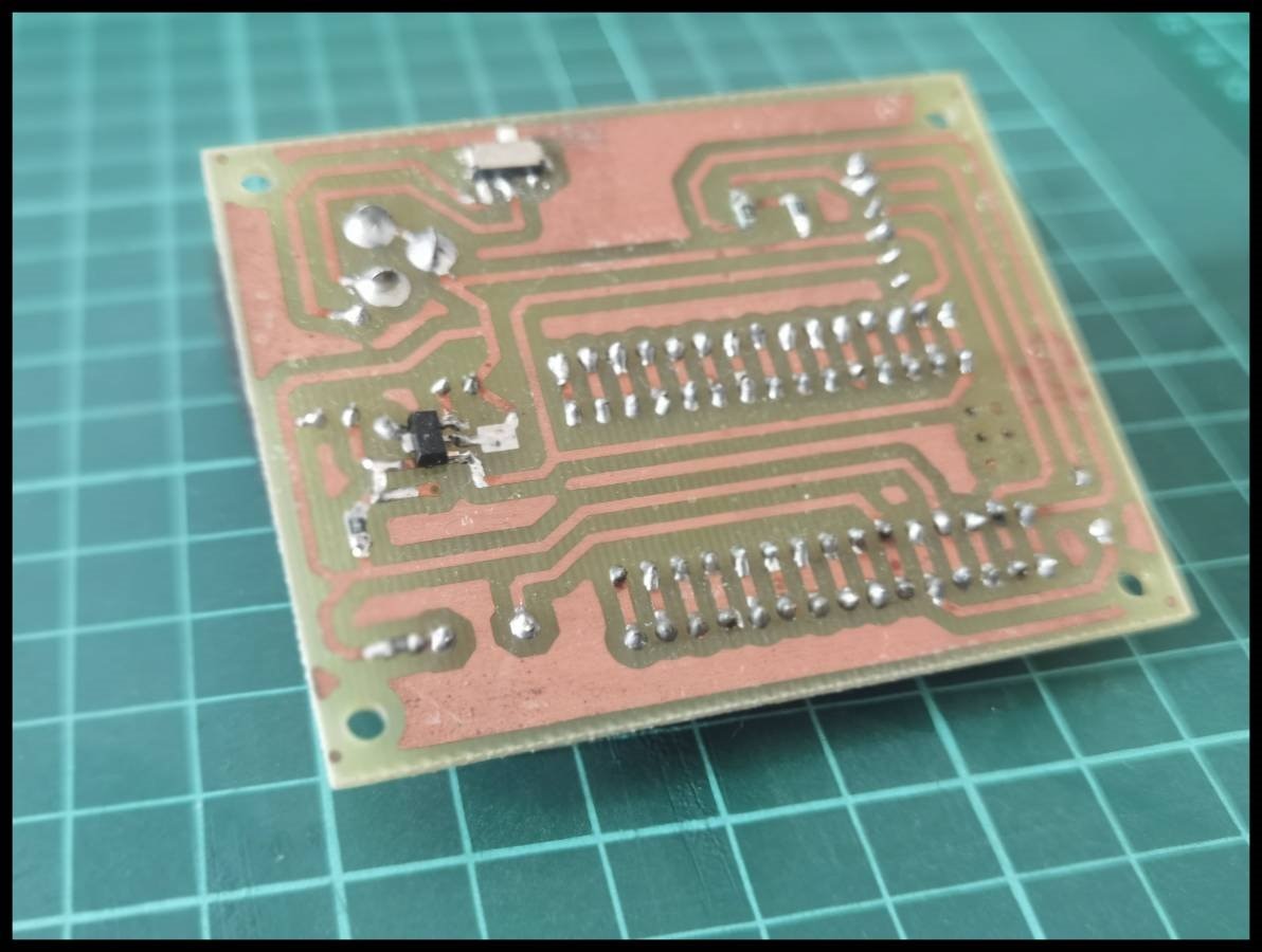 | 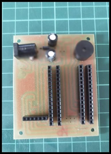 |
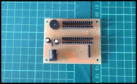 | |
Now we have finalized the hardware required to complete the project, next we shall see the software required.
SOFTWARE
Now we have finalized the hardware required to complete the project, next we shall see the software required. The main software we needed is the Arduino IDE.
-

javagoza
-
Cancel
-
Vote Up
0
Vote Down
-
-
Sign in to reply
-
More
-
Cancel
Comment-

javagoza
-
Cancel
-
Vote Up
0
Vote Down
-
-
Sign in to reply
-
More
-
Cancel
Children