element14 Community
element14 Community
    Register Log In
  • Site
  • Search
  • Log In Register
  • Community Hub
    Community Hub
    • What's New on element14
    • Feedback and Support
    • Benefits of Membership
    • Personal Blogs
    • Members Area
    • Achievement Levels
  • Learn
    Learn
    • Ask an Expert
    • eBooks
    • element14 presents
    • Learning Center
    • Tech Spotlight
    • STEM Academy
    • Webinars, Training and Events
    • Learning Groups
  • Technologies
    Technologies
    • 3D Printing
    • FPGA
    • Industrial Automation
    • Internet of Things
    • Power & Energy
    • Sensors
    • Technology Groups
  • Challenges & Projects
    Challenges & Projects
    • Design Challenges
    • element14 presents Projects
    • Project14
    • Arduino Projects
    • Raspberry Pi Projects
    • Project Groups
  • Products
    Products
    • Arduino
    • Avnet Boards Community
    • Dev Tools
    • Manufacturers
    • Multicomp Pro
    • Product Groups
    • Raspberry Pi
    • RoadTests & Reviews
  • Store
    Store
    • Visit Your Store
    • Choose another store...
      • Europe
      •  Austria (German)
      •  Belgium (Dutch, French)
      •  Bulgaria (Bulgarian)
      •  Czech Republic (Czech)
      •  Denmark (Danish)
      •  Estonia (Estonian)
      •  Finland (Finnish)
      •  France (French)
      •  Germany (German)
      •  Hungary (Hungarian)
      •  Ireland
      •  Israel
      •  Italy (Italian)
      •  Latvia (Latvian)
      •  
      •  Lithuania (Lithuanian)
      •  Netherlands (Dutch)
      •  Norway (Norwegian)
      •  Poland (Polish)
      •  Portugal (Portuguese)
      •  Romania (Romanian)
      •  Russia (Russian)
      •  Slovakia (Slovak)
      •  Slovenia (Slovenian)
      •  Spain (Spanish)
      •  Sweden (Swedish)
      •  Switzerland(German, French)
      •  Turkey (Turkish)
      •  United Kingdom
      • Asia Pacific
      •  Australia
      •  China
      •  Hong Kong
      •  India
      •  Korea (Korean)
      •  Malaysia
      •  New Zealand
      •  Philippines
      •  Singapore
      •  Taiwan
      •  Thailand (Thai)
      • Americas
      •  Brazil (Portuguese)
      •  Canada
      •  Mexico (Spanish)
      •  United States
      Can't find the country/region you're looking for? Visit our export site or find a local distributor.
  • Translate
  • Profile
  • Settings
Enchanted Objects
  • Challenges & Projects
  • Design Challenges
  • Enchanted Objects
  • More
  • Cancel
Enchanted Objects
Blog Multimeter inbox 1: The idea
  • Blog
  • Forum
  • Documents
  • Polls
  • Files
  • Events
  • Mentions
  • Sub-Groups
  • Tags
  • More
  • Cancel
  • New
  • Share
  • More
  • Cancel
Group Actions
  • Group RSS
  • More
  • Cancel
Engagement
  • Author Author: kidiccurus
  • Date Created: 26 Mar 2015 4:55 PM Date Created
  • Views 1250 views
  • Likes 5 likes
  • Comments 9 comments
  • yun
  • enchanted_objects
  • inbox_multimeter
  • arduino
Related
Recommended

Multimeter inbox 1: The idea

kidiccurus
kidiccurus
26 Mar 2015

I would like to start by thanking everyone involved in making this design challenge happen. Things like this are great for the electronics community and are one of the reasons I got insterested in electronics. Thank you.


Problem: I don't check my inbox on Element 14 for new messages at regular intervals. This leads to messages either sitting around for a few days or me checking in to find only an empty inbox.

Solution: Repurpose an old analogue rapiest multimeter to display the number of messages in my inbox via the voltage indicator.

image

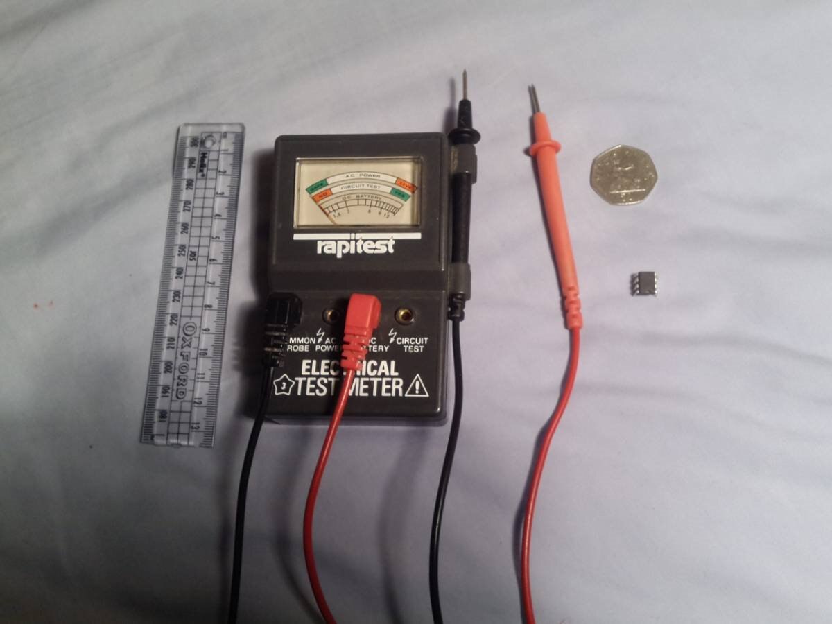
/\ fig 1 This is the meter I want to use, along with some objects for scale

image

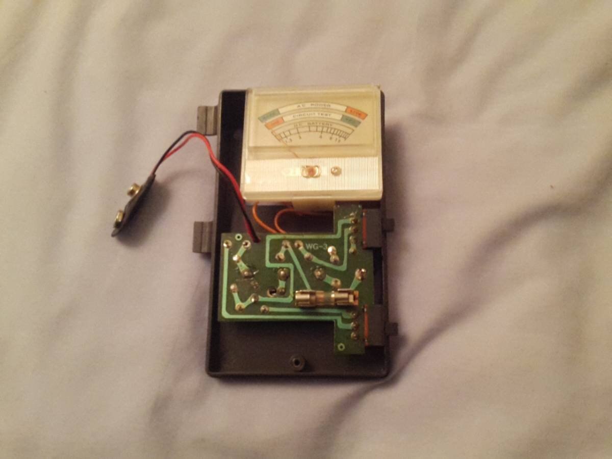
/\ fig 2 And here we have a photo of the meters circuitry


Hardware Design: The idea is to drive the display using a motor driver board and PWM. Conveniently the meter has a range of about 12 volts so a standard DC wall wart should be fine for powering this This does mean that the device can't display more than 12 messages, but hopefully I will check in regularly enough for this not to be an issue. Any values greater than 12 can easily just be have to be displayed as 12, or alternatively by a needle alternating between 0 and 12. The wall wart could also power the main board of the unit via a voltage regulator. For the main board I intend to use an Arduino Yun. The meter will conveniently operate on DC voltage mode with no power source so powering it will not be an issue. It also features 2 convenient side mounted switches that can easily be used to turn the unit on and off. It may also be worth adding an LED backlight to the unit that can be driven by the Yun and turned off with the other switch.

image

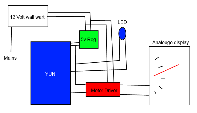
/\ fig 3 A quick visual overview of the hardware. Note that for simplicity, some passive components and the switches and the circuitry from the multimeter have been ommited.


Software design: The first stage of software will run on the Linux half of the Yun. Using Python it will regularly load and parse my inbox to find the message count. this will then be passed on to the ATmega. The mega will compare the value it receives to a table of PWM values and then use this to power the motor driver and move the needle to the correct position, or possibly between positions in the case of more than 12 posts, but this will be handled as a special case. The Yun can also drive the backlight with PWM, potentially allowing for either a heartbeat effect or a brightness increasing with message count.


Success Criteria: I will deem the project a success if:

•It can accurately and reliably display the number of messages in my inbox up to 12

•The system can cope with more than 12 messages in a way that does not result in catastrophic failure

•The display can be read in darkness with an LED backlight

•The unit is powered by a single DC wall wart


Challenges in this project:

• Writing the code for the parser

   -Whilst I do have some experience of python, I have only coded something like this once in the past

•Calibrating the pwm

   -I will probably needs a separate program to test pwm values via a serial terminal. I will probably use an arduino Leonardo for this, simply because I feel more confident     using it

•Comunicating between Linux and the Atmega

   -Having never used a Yun, this appears to be one of the challenges specific to the platform


Edit: Apologies for the delay in posting this. I have recently changed my PC and have been having some issues posting. These issues have not yet been resolved, but I am now able to post through another device so updates should now be a little more frequent.

  • Sign in to reply

Top Comments

  • kidiccurus
    kidiccurus over 10 years ago in reply to fvan +2
    Thank you both for your replys. Both articles appears relatively helpful to take some code from in the programming stage, so thanks for that. As for using a servo, the dial I have taken from the meter…
  • kidiccurus
    kidiccurus over 10 years ago in reply to Workshopshed +1
    Thank you very much for your reply. My Yun has yet to arriveas well, but if it is similar to the Leonardo then I hope I won't have to many issues. I have already done some work with the Uno that I have…
  • mcb1
    mcb1 over 10 years ago +1
    Samuel I think you'll find it doesn't actually require 12v on the meter itself to drive it fullscale. One clue is that it used a 9v battery to drive the continuity to fullscale, but apart from some automotive…
Parents
  • mcb1
    mcb1 over 10 years ago

    Samuel

    I think you'll find it doesn't actually require 12v on the meter itself to drive it fullscale.

    One clue is that it used a 9v battery to drive the continuity to fullscale, but apart from some automotive type meters, most are a low current meter across a resistor.


    I'd suggest tracing the circuit out and then you'll know what you're dealing with, and can adjust how you drive it.

    It will still work using your PWM technique.


    Mark

    • Cancel
    • Vote Up +1 Vote Down
    • Sign in to reply
    • More
    • Cancel
  • kidiccurus
    kidiccurus over 10 years ago in reply to mcb1

    Thank you for your reply. I was thinking of driving it via the built in circuitry in voltage mode, but I may try and test without to see if I can omit the motor driver and instead drive directly from one of the pins. If I can do this then I may the LED driver shield for a more interesting back light.

    • Cancel
    • Vote Up 0 Vote Down
    • Sign in to reply
    • More
    • Cancel
  • mcb1
    mcb1 over 10 years ago in reply to kidiccurus

    Samuel

    I strongly suggest using a high value resistor in series during your testing.

    I've seen someone bend the needle, and damage the coil.


    You might be able to stick the meter across 12v and measure what the meter leads show to get an idea.


    Good luck I like the interface to analogue.

    Mark

    • Cancel
    • Vote Up 0 Vote Down
    • Sign in to reply
    • More
    • Cancel
  • kidiccurus
    kidiccurus over 10 years ago in reply to mcb1

    Thanks for the advice, I have already done some testing and have concluded that a resistor is needed. My next blog post may take a little while due to the problems with my PC, but I will try and get it up in the next few days.

    • Cancel
    • Vote Up 0 Vote Down
    • Sign in to reply
    • More
    • Cancel
Comment
  • kidiccurus
    kidiccurus over 10 years ago in reply to mcb1

    Thanks for the advice, I have already done some testing and have concluded that a resistor is needed. My next blog post may take a little while due to the problems with my PC, but I will try and get it up in the next few days.

    • Cancel
    • Vote Up 0 Vote Down
    • Sign in to reply
    • More
    • Cancel
Children
No Data
element14 Community

element14 is the first online community specifically for engineers. Connect with your peers and get expert answers to your questions.

  • Members
  • Learn
  • Technologies
  • Challenges & Projects
  • Products
  • Store
  • About Us
  • Feedback & Support
  • FAQs
  • Terms of Use
  • Privacy Policy
  • Legal and Copyright Notices
  • Sitemap
  • Cookies

An Avnet Company © 2025 Premier Farnell Limited. All Rights Reserved.

Premier Farnell Ltd, registered in England and Wales (no 00876412), registered office: Farnell House, Forge Lane, Leeds LS12 2NE.

ICP 备案号 10220084.

Follow element14

  • X
  • Facebook
  • linkedin
  • YouTube