element14 Community
element14 Community
    Register Log In
  • Site
  • Search
  • Log In Register
  • About Us
  • Community Hub
    Community Hub
    • What's New on element14
    • Feedback and Support
    • Benefits of Membership
    • Personal Blogs
    • Members Area
    • Achievement Levels
  • Learn
    Learn
    • Ask an Expert
    • eBooks
    • element14 presents
    • Learning Center
    • Tech Spotlight
    • STEM Academy
    • Webinars, Training and Events
    • Learning Groups
  • Technologies
    Technologies
    • 3D Printing
    • FPGA
    • Industrial Automation
    • Internet of Things
    • Power & Energy
    • Sensors
    • Technology Groups
  • Challenges & Projects
    Challenges & Projects
    • Design Challenges
    • element14 presents Projects
    • Project14
    • Arduino Projects
    • Raspberry Pi Projects
    • Project Groups
  • Products
    Products
    • Arduino
    • Avnet Boards Community
    • Dev Tools
    • Manufacturers
    • Multicomp Pro
    • Product Groups
    • Raspberry Pi
    • RoadTests & Reviews
  • Store
    Store
    • Visit Your Store
    • Choose another store...
      • Europe
      •  Austria (German)
      •  Belgium (Dutch, French)
      •  Bulgaria (Bulgarian)
      •  Czech Republic (Czech)
      •  Denmark (Danish)
      •  Estonia (Estonian)
      •  Finland (Finnish)
      •  France (French)
      •  Germany (German)
      •  Hungary (Hungarian)
      •  Ireland
      •  Israel
      •  Italy (Italian)
      •  Latvia (Latvian)
      •  
      •  Lithuania (Lithuanian)
      •  Netherlands (Dutch)
      •  Norway (Norwegian)
      •  Poland (Polish)
      •  Portugal (Portuguese)
      •  Romania (Romanian)
      •  Russia (Russian)
      •  Slovakia (Slovak)
      •  Slovenia (Slovenian)
      •  Spain (Spanish)
      •  Sweden (Swedish)
      •  Switzerland(German, French)
      •  Turkey (Turkish)
      •  United Kingdom
      • Asia Pacific
      •  Australia
      •  China
      •  Hong Kong
      •  India
      •  Korea (Korean)
      •  Malaysia
      •  New Zealand
      •  Philippines
      •  Singapore
      •  Taiwan
      •  Thailand (Thai)
      • Americas
      •  Brazil (Portuguese)
      •  Canada
      •  Mexico (Spanish)
      •  United States
      Can't find the country/region you're looking for? Visit our export site or find a local distributor.
  • Translate
  • Profile
  • Settings
Energy Harvesting Design Challenge
  • Challenges & Projects
  • Design Challenges
  • Energy Harvesting Design Challenge
  • More
  • Cancel
Energy Harvesting Design Challenge
Blog CO sensor
  • Blog
  • Forum
  • Documents
  • Files
  • Mentions
  • Sub-Groups
  • Tags
  • More
  • Cancel
  • New
  • Share
  • More
  • Cancel
Group Actions
  • Group RSS
  • More
  • Cancel
Engagement
  • Author Author: gelmi
  • Date Created: 15 Jun 2013 9:10 AM Date Created
  • Views 1679 views
  • Likes 1 like
  • Comments 5 comments
  • low_power
  • low_energy
  • 32_bit
  • temperature
  • enery_efficiency
  • energy_harvesting
  • efm32
  • energy_micro
  • self_powered
  • kit
  • adc
  • consumer_electronics
  • energy_harvesting_challenge
Related
Recommended

CO sensor

gelmi
gelmi
15 Jun 2013

To sense carbon monoxide concentration, I took many sensors into consideration. The one I have chosen for my design is TGS 5042 from Figaro.

image

There are 3 main reasons that this sensor is perfect for my application:

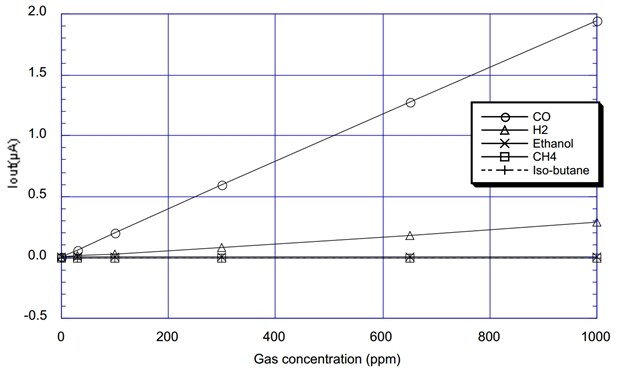
  • This is an electrochemical sensor – it does not need power supply. It is filled with some chemicals which in reaction with carbon monoxide produce current and the sensor works as current source. Plus, other gases and temperature (especially home environment temperature range) has almost zero influence on it and the lifetime is minimum 7 years.
  • It does not need any fancy external chips and circuits. Carbon monoxide concentration is linear to the current value.
  • It is designed for battery operated systems. It has only two lead and there is no need to heat it up (5V) before reading the measurements. Additionally, the reaction time for the gas concentration is below 60 seconds, which is very important for people safety.


The datasheet suggests this measurement circuit (current-to-voltage converter):

image

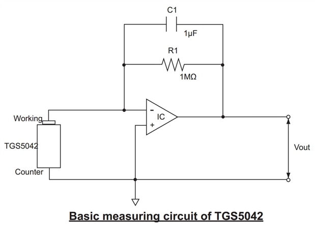
I have tested it and it works great, but … it requires external opamp with dual supply. With energy harvesting there is a problem with energy availability so with adding additional charge pump or other DC/DC (inverter) we would lose some vital energy. That is why I wanted to use the opamp which is already inside the EFM32 chip on the STK. The problem is that it is only single supply opamp. So, I propose another measurement circuit:

image

The 1k resistor next to the sensor is for protection purposes. The datasheet says that the sensor should not be polarized with voltages above +/-10mV (when storing the sensor, datasheet suggests to short-circuit it). While my circuit is operational, there would be no problem, but I plan to turn off everything that I can, whenever I can to save power. That is why I have included this 1k resistor to protect the sensor (even in a high carbon monoxide concentration) when the internal opamp is disabled. I have used the opamp in non-inverting configuration (cause there is only one power supply and I do not want to make any external circuits for virtual ground) and that is why I had to invert the sensor leads.

The sensor with STK is operational. The voltage to ppm conversion can be applied with the linear graph from the datasheet. The output voltage from the opamp takes form of: Vout = Isensor * R3 * ((R1 / R2) +1). It can be read with EFM32’s ADC.

image

The gain is about 106 with the circuit I propose, so the 3V single supply amp can detect concentration far above 1000 ppm which is more than sufficient for home appliences.

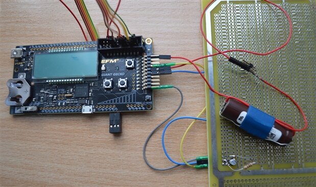
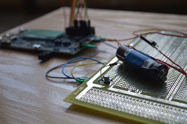
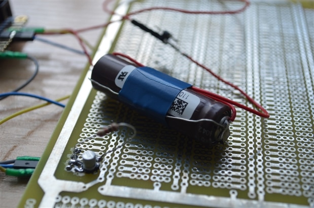
I have filmed a short sensor test video, but I need some time to convert and upload it, so right now I present only the picture of the setup. I will upload the video as soon as I find some time.

image

image

image

  • Sign in to reply
  • gelmi
    gelmi over 12 years ago

    I would still like to know the value of CO concentration, even if the error would be maybe 10%, so I will use opamp with ADC every 60 seconds (that is the max time response from the sensor). Nevertheless, the use of comparator is not a bad idea. I have to think about it. It would be a good idea to start the alarm when the concentration rises to a dangerous level between these 60 readings. I have to check how to implement it and on the other hand not to use a lot of energy. Thanks!

    • Cancel
    • Vote Up 0 Vote Down
    • Sign in to reply
    • More
    • Cancel
  • vsluiter
    vsluiter over 12 years ago in reply to gelmi

    Hey Gelmi,


    I think I can agree with your observation; I only thought that since you're planning to do a level detection it might be better / more energy efficient to use a comparator instead of an opamp.

    • Cancel
    • Vote Up 0 Vote Down
    • Sign in to reply
    • More
    • Cancel
  • gelmi
    gelmi over 12 years ago

    Thank you for your insight. You have already answered to one of the things that bothers you. Yes, of course this 10^6 amplification value is the combination of both opamp and first stage resistor circuit. Sorry that my description was not clear enough. A for the bias currents I also could not find their values. But still I think that EFM32 chip's internal opamp does not have as large bias current as it would make the readings so untrue.

    I realize that good opamps, like AD620 with input bias which is max 1nA are perfect for this job, but EFM32 cannot be that bad image. I have checked the sensor with both analog front-ends (EFM32 and external opamp with little bias current) in similar CO gas concentration environment (jar) and Vout readings were similar, not equal but with resonable difference, less then 10%. Figaro sensor itself in this configuration has +/-5% error and my application has to detect hazardous concentration, so in my opinion the threshold level is more important than the error (of course in resonable margin). Plus, in almost CO free environment (ouside), the Voutput is about 0,2 mV.

    Please , let me know what do you think about my point of view.

    • Cancel
    • Vote Up 0 Vote Down
    • Sign in to reply
    • More
    • Cancel
  • vsluiter
    vsluiter over 12 years ago

    Hello Gelmi!


    Nice post, good to look at the opamp feature of the EFM32, I haven't been able to explore that. However, I do have a slight warning for you; the open loop gain of the opamp is only 100dB, which is a factor 10^(100/20)  = 100000. You won't be able to get 10^6 gain out of that opamp. When these numbers are true (I'm a bit worried about the claim in the datasheet that the numbers are derived from simulations) you won't be able to get the full range of amplification you had wanted. With the high gain you ask, the bandwith also reduces considerably. I've made a very simple opamp model below with a 120 dB open loop gain and a pole at 60Hz, and you see that it takes quite a while to get to the desired output voltage.

    image

    The other problem I see in this circuit and in the specs of the opamp is that the bias current of the opamp is not specified. Unfortunately, a lot of opamps with rail-to-rail inputs have an highly input-voltage dependant input bias current, which could mess up your measurement.


    I guess however that it is still possible to read out this sensor, but either with an external opamp with shutdown, or by measuring the current (first schematic in you post), but offsetting both the counter electrode and the '+' input of the opamp with an offset voltage from an DA converter.That will leave less room for amplification, but maybe you could do some oversampling?


    Interesting sensors!


    EDIT:

    On a second look, I noticed that you take the first 60dB gain by using the resistor as a current->voltage converter, and then use the opamp for another 60dB, which is very well possible with 100dB open loop gain. Which defeats my complete simulation above, but does stress the influence of the input bias current.

    EDIT2:

    I just realized that my calculation in the LTSpice screenshot is off; I had used 380rad/s for 60Hz, whereas it should be the timeconstant, so it had to be 1-over-380.....

    • Cancel
    • Vote Up 0 Vote Down
    • Sign in to reply
    • More
    • Cancel
  • DAB
    DAB over 12 years ago

    Good post.


    I like your solution to the dual voltage problem.

    You might also consider going to a transistor or resistive bridge approach, but it looks like you are ready for your next step.


    Look forward to seeing your sensor in action.


    DAB

    • Cancel
    • Vote Up 0 Vote Down
    • Sign in to reply
    • More
    • Cancel
element14 Community

element14 is the first online community specifically for engineers. Connect with your peers and get expert answers to your questions.

  • Members
  • Learn
  • Technologies
  • Challenges & Projects
  • Products
  • Store
  • About Us
  • Feedback & Support
  • FAQs
  • Terms of Use
  • Privacy Policy
  • Legal and Copyright Notices
  • Sitemap
  • Cookies

An Avnet Company © 2025 Premier Farnell Limited. All Rights Reserved.

Premier Farnell Ltd, registered in England and Wales (no 00876412), registered office: Farnell House, Forge Lane, Leeds LS12 2NE.

ICP 备案号 10220084.

Follow element14

  • X
  • Facebook
  • linkedin
  • YouTube