


Introduction
We're now halfway through the Experimenting with Extreme Environments challenge, sponsored by Hammond Manufacturing and Element14. This marks my third blog, detailing the progress of my UrbanRest Guardian project, aimed at monitoring and classifying nighttime noises on city streets.
Let me walk you through the past two weeks. After presenting my project and meticulously studying the components, it was time to dive into the design and construction phase.
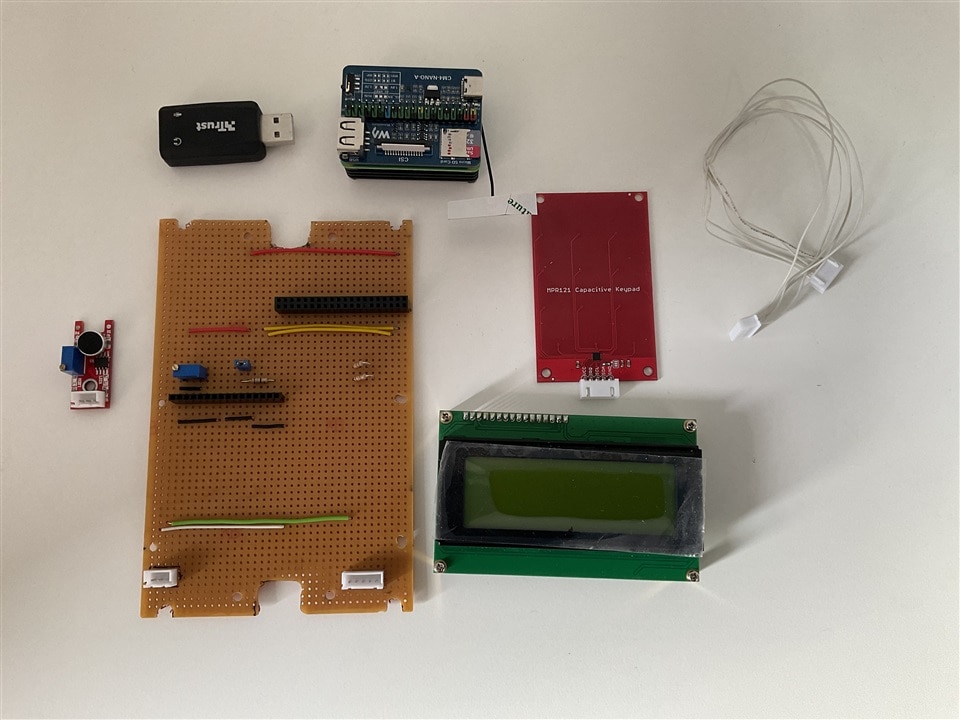
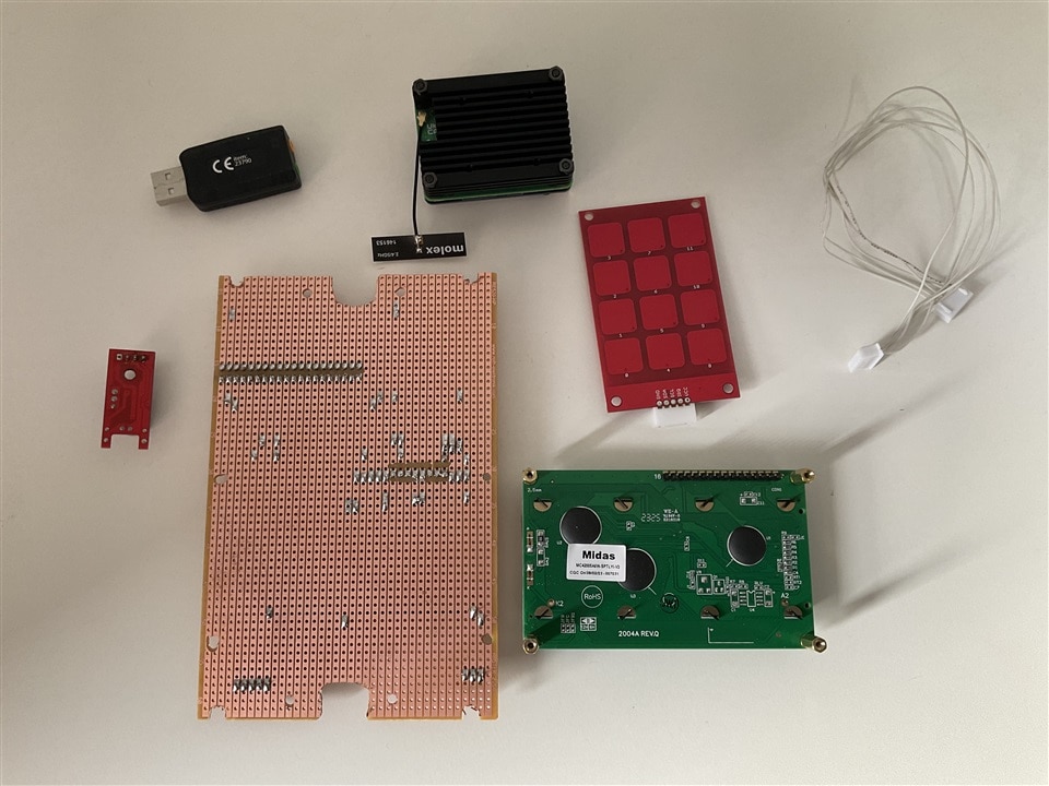
The biggest challenge? Figuring out how to arrange all the components inside the enclosure. I had quite the lineup: the Raspberry Pi4 Compute Module , a 12000 mAh battery, two external connectors, a 4x20 Midas display, a USB sound card, a sound sensor and a 12-position capacitive keyboard.
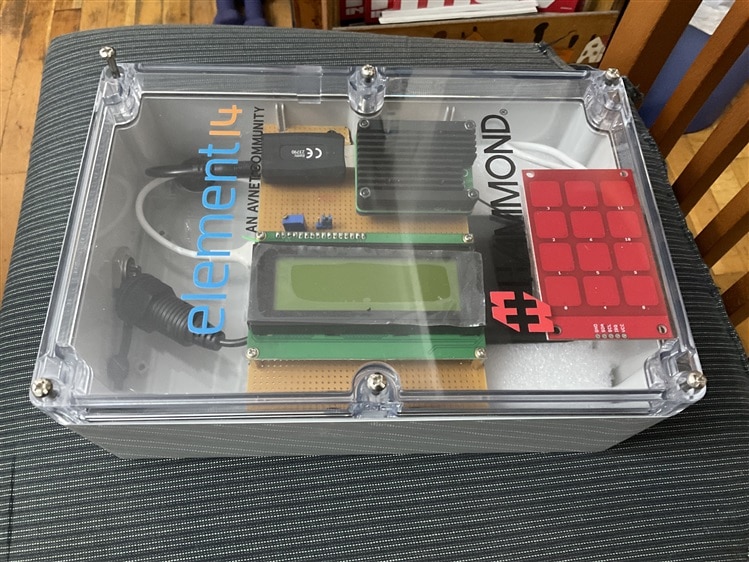
Initially, I tried a vertical layout, influenced by the engravings on the transparent enclosure cover. But it quickly became clear that if I wanted the display to be easily readable, my options were limited. So, I gave a horizontal arrangement a shot, inspired by a layout I saw in Ralphjy's project.
Surprisingly, everything fell into place much more smoothly in the horizontal layout.
Table of Contents
- Introduction
- Testing Component Arrangements in Enclosure
- Integrating Capacitive Keyboard for Device Interaction
- Configuring the Capacitive Keyboard
- Introducing an Adjustable Sound Sensor
- Designing the PCB on stripboard to connect the components
- Designing the foam bed to house the battery
- Constructing the foam bed to house the battery
- Constructing the PCB on stripboard to connect the components
- Assembling the cables
- Experimenting with the microphone inside the enclosure
- Summary and conclusions
- References
- UrbanRest Guardian blog series
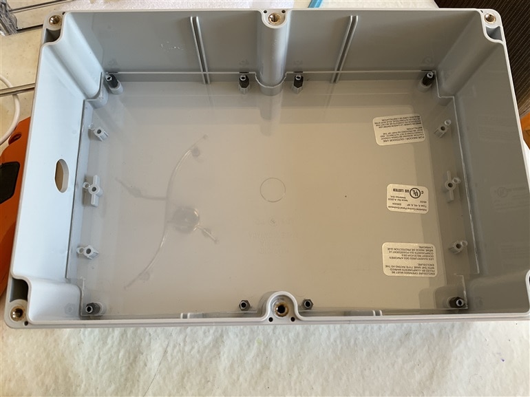
Testing Component Arrangements in Enclosure
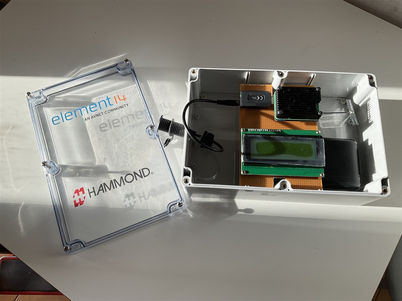
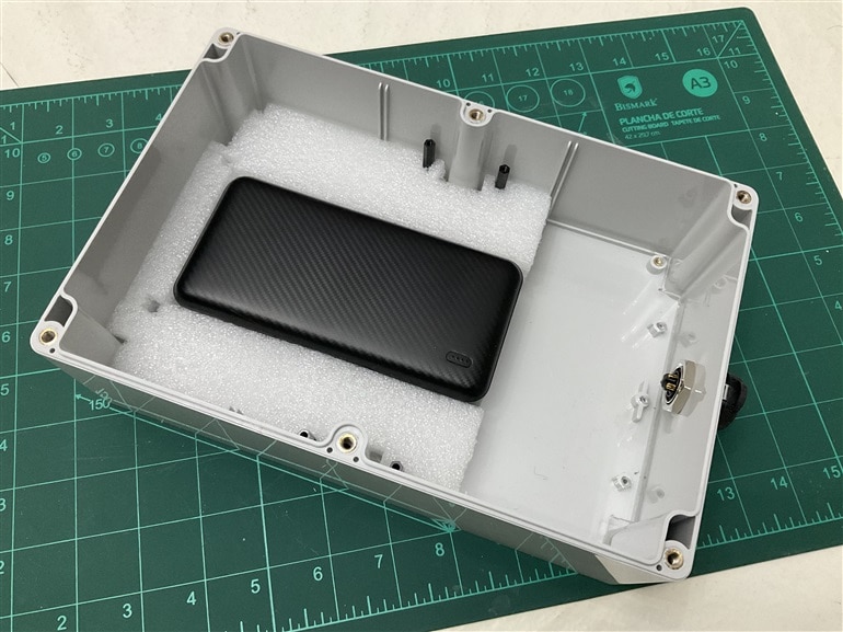
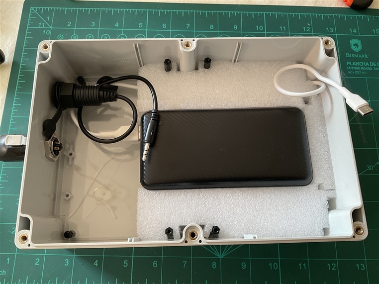
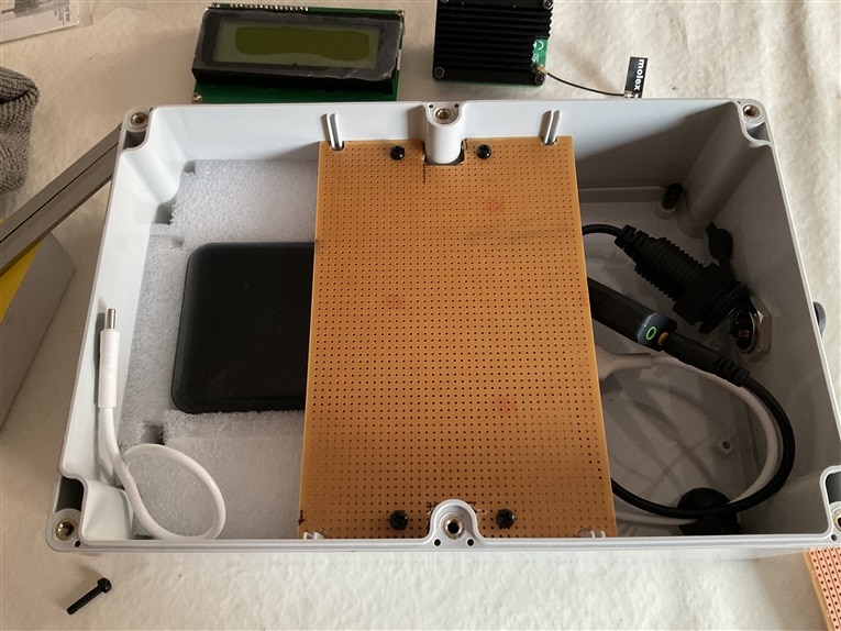
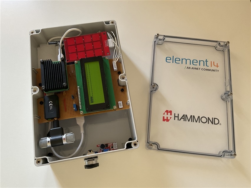
In the images, I show the initial trials of the horizontal layout. However, these trials unveiled several issues: the upper stripboard lacked rigidity to support the display, Raspberry Pi 4 compute module, and USB sound card; securing the 12000 mAh battery posed a challenge; and organizing the wiring and connecting the capacitive keyboard to the rest of the system proved tricky.
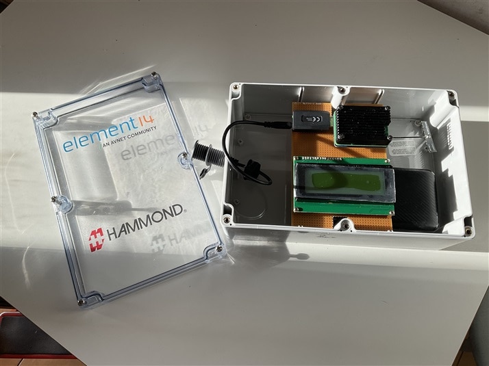
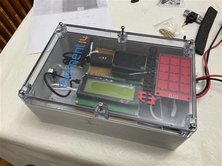
On the other hand, this layout left much more free space, resulting in a tidier arrangement and greatly facilitating assembly and disassembly.
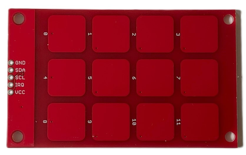
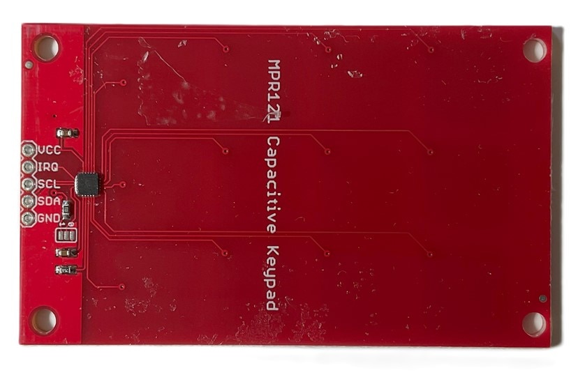
Integrating Capacitive Keyboard for Device Interaction
I've added a new capacitive keyboard, MPR121, to the project for interacting with the device. Originally, communication was going to be solely remote, using the WiFi connection of the Raspberry Pi 4 compute module. However, out of curiosity, I wanted to explore the possibility of interacting with a capacitive keyboard placed on the inner side of the transparent lid of the enclosure. The cover thickness slightly exceeds the distance specifications provided by the keyboard manufacturer, so it'll be an experiment to see if this keyboard can be effectively used.
Configuring the Capacitive Keyboard
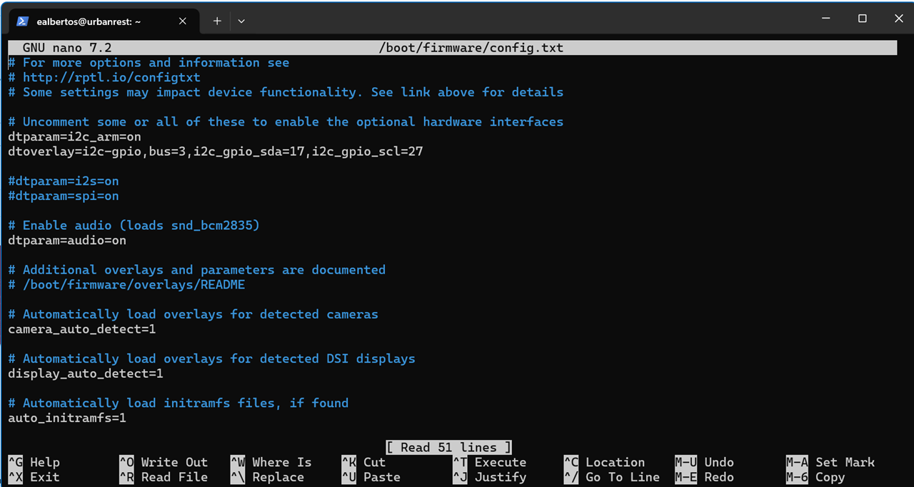
Edit the firmware config file:
sudo nano /boot/firmware/config.txt
# Uncomment some or all of these to enable the optional hardware interfaces
dtparam=i2c_arm=on
dtoverlay=i2c-gpio,bus=3,i2c_gpio_sda=17,i2c_gpio_scl=27
Reboot the system
sudo reboot -h now
sudo i2cdetect -y 3
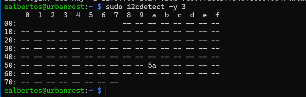
The keyboard is now responsive at address 5a on bus 3 of I2C.
Introducing an Adjustable Sound Sensor
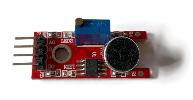
To capture sound only during periods of bothersome noise, when a certain threshold is surpassed, I've incorporated an adjustable sound sensor with an LM393 comparator. This sensor triggers the events of sound capture and analysis. The concept is to place the sensor inside the enclosure. While I'm uncertain if this will effectively capture those noises, it's another experiment worth testing.
Some python code to test the sound sensor. It will be connected to GPIO26
#!/usr/bin/python
import RPi.GPIO as GPIO
import time

#GPIO SETUP
sound = 26

GPIO.setmode(GPIO.BCM)
GPIO.setup(sound, GPIO.IN)

def callback(sound):
    print "Sound Detected!"

GPIO.add_event_detect(sound, GPIO.FALLING, bouncetime=300)

GPIO.add_event_callback(sound, callback)  # assign function to GPIO PIN, Run function on change

# infinite loop
while True:
    time.sleep(1)
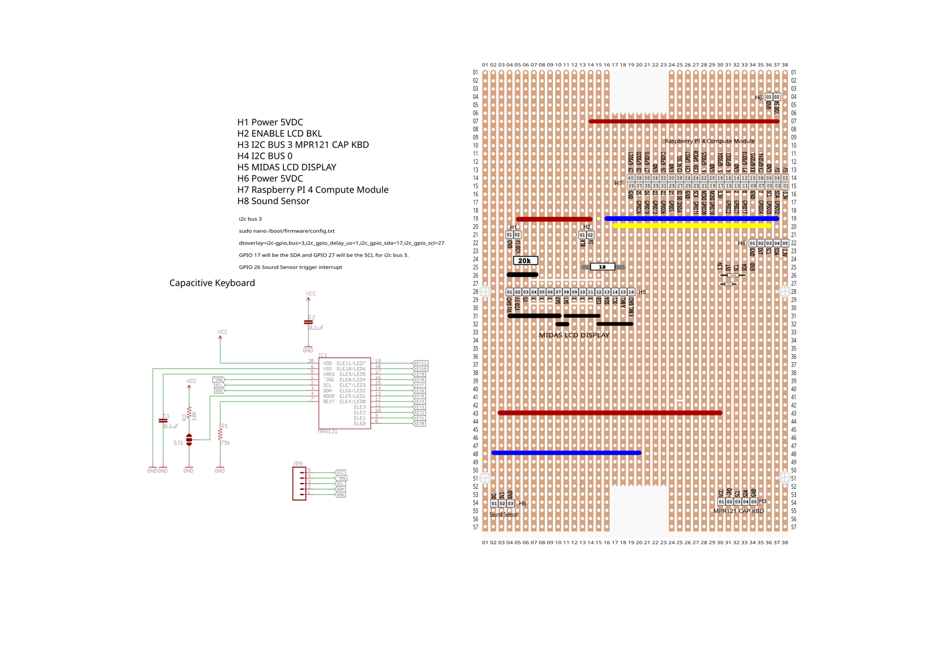
Designing the PCB on stripboard to connect the components
In the previous blog, I demonstrated how I connected the Midas I2C LCD Display to the Raspberry Pi 4 compute module using a breadboard and a jumble of messy wires. While it was sufficient for testing purposes, it lacked safety and aesthetic appeal.

Therefore, for the prototype construction, I plan to tidy up all those connections by soldering them onto a stripboard. The next step involves a diagram I sketched on graph paper using a pencil and eraser.
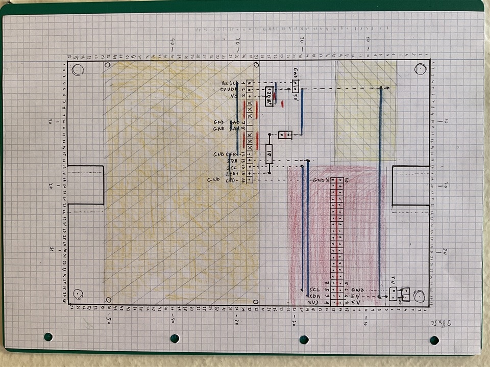
I find this method quicker than creating it on a computer; I'll work on a digital version later.
...
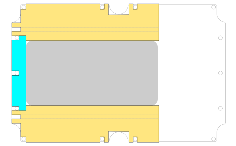
Designing the foam bed to house the battery
As shown in the photo of the test arrangement, the battery sits on a lower level at the base of the box, but there's nothing securing it in place.
I considered various options, like crafting a support from wood or acrylic plastic, or 3D printing a structure for the battery. However, due to an injury to my right hand that limits my ability to exert force with it, I thought of opting for a softer material. Discussing it with my family, we came up with the idea of making a foam bed for the battery.
Constructing the foam bed to house the battery
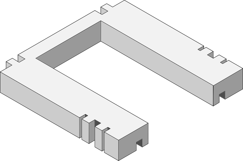
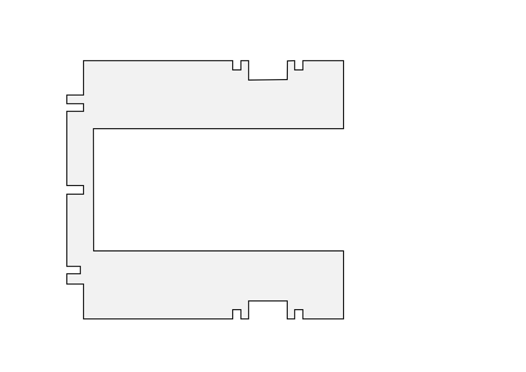
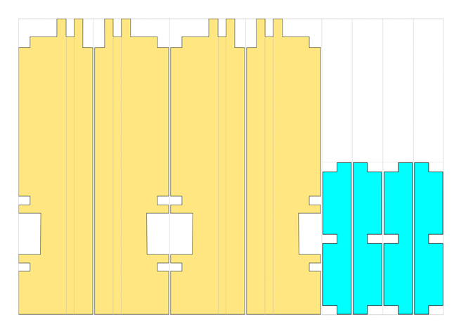
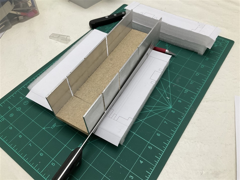
I had a foam sheets left over from the packaging of a small HDMI display. I designed the bed like a puzzle to maximize the use of the foam sheet.
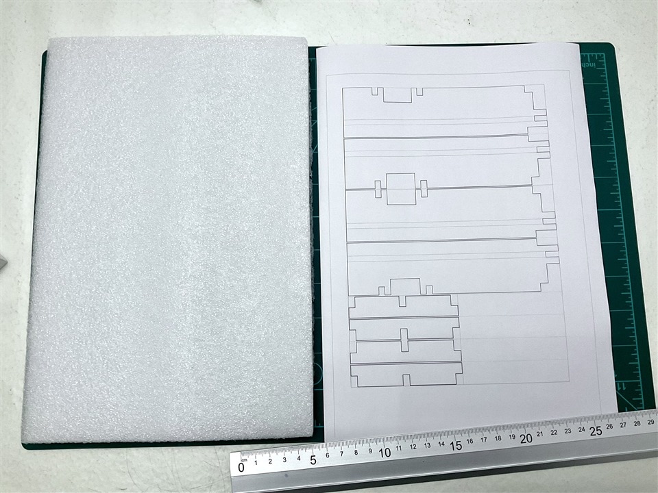
Cutting the foam is extremely simple with a sharp blade or knife. In the image, I used a typical ham knife for slicing Iberian ham.
The foam bed rests on the inner panel made of acrylic plastic. It includes pass-through holes for the standoffs that will support the stripboard panel with the interconnected electronic devices. Additionally, it features cable guides at the bottom to help organize the wiring.
Finally, a small panel that will be inserted into the PCB rails of the box will secure the battery on the side that remains free. The top part of the battery is secured by some standoffs at the bottom of the stripboard.
Constructing the PCB on stripboard to connect the components
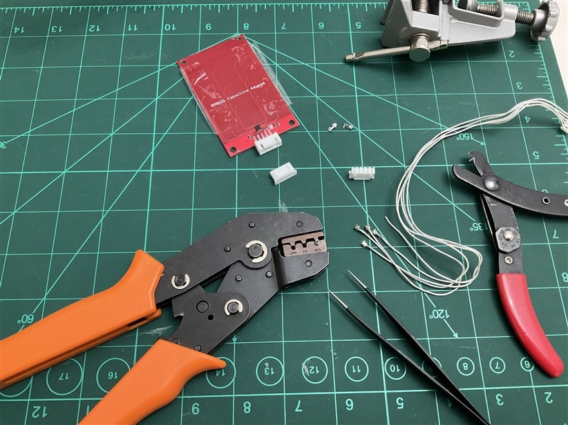
The PCB construction was carried out on a single-sided stripboard prototype board. Both the capacitive keyboard and the sound sensor are connected using cables with JST-XH connectors, which have a pin pitch of 2.54 mm. I used a ROTH ELEKTRONIK RE520-HP Prototyping Board Eurocard, FR2, Epoxy Paper, 1.5mm, 100mm x 160mm.
The Raspberry Pi 4 compute module is inserted into a 2x40 female header, while the MIDAS LCD display is placed on a 1x16 female header.
A jumper cap allows you to turn the backlight LED of the LCD display on or off.
The 20 kOhm Bourns potentiometer enables adjustment of the LCD display contrast. The 18 Ohm resistor serves to limit the current of the LED backlight.
Assembling the cables
For assembling the connection cables, I used a specialized crimping tool for the JST connectors.
Experimenting with the microphone inside the enclosure
I haven't drilled the enclosure yet to install the TRS audio connector for the external microphone. I thought I could conduct tests with the microphone inside the box first. This would simplify the device construction considerably. So, I'll compare the spectrograms of the sound by placing the microphone both inside the sealed enclosure and in its intended position outside the enclosure. Testing in both scenarios will determine if the device can accurately classify the sound in both situations.
Construction noises on a nearby street. The video demonstrates sound capture both with the enclosure lid removed and with the enclosure lid in place.
Same test indoors with the noise of a radio broadcast from a Spanish radio station.
Finally, repeating the test outdoors with the background noise of two air conditioning units from a nearby building.
Summary and conclusions
This has been my journey with the enclosure over the past two weeks. The tests with the capacitive keyboard have been somewhat discouraging. While the keyboard works well outside the box, it's unable to recognize keystrokes through the polycarbonate of the enclosure lid, which may be too thick. However, it manages to detect keystrokes under other acrylic plastic sheets. I'll conduct further tests or try to increase the surface area of the keys.
The next steps will involve starting to automatically record sounds and preparing the sound classification models.
Update 2024-05-04
After carefully reading the datasheet for the MPR121 capacitive touch sensor I've written my own library to drive to configure the sensor and it works quite well for the Hammond enclosure. In the video a sample of the first tests.
References
UrbanRest Guardian blog series
Want to know more about this project? Check out the full blog series here:
- Blog 1 - UrbanRest Guardian - Project Introduction
- Blog 2 - UrbanRest Guardian - First contact with the kit components.
- Blog 3 - UrbanRest Guardian - Prototype Construction Journey
- Blog 4 - UrbanRest Guardian - Classifying Urban Sounds
- Blog 5 - UrbanRest Guardian - Remote Monitoring
- Final Blog - UrbanRest Guardian - Smart Street Noise Monitor


