Unboxing Experiment Kit
For Extreme Environment Home Assistance Sensors
1. Introduction
Fortunately being selected for Experimenting with Extreme Environments, I proposed project Extreme Environment Home Assistance Sensors to show how Home Assitance Operation System runs on harsh and extreme environment for Smart Home facilities, exposed to whatever temperature, moisture, humidity, vibration, dust, even vibration and mechanical impact.
In centre of this experiment is anHAMMOND IP68-rated enclosure, holding electronic components and running robust software based on Raspberry Pi Computing Module 4(Pi CM4).
![]() and
and 
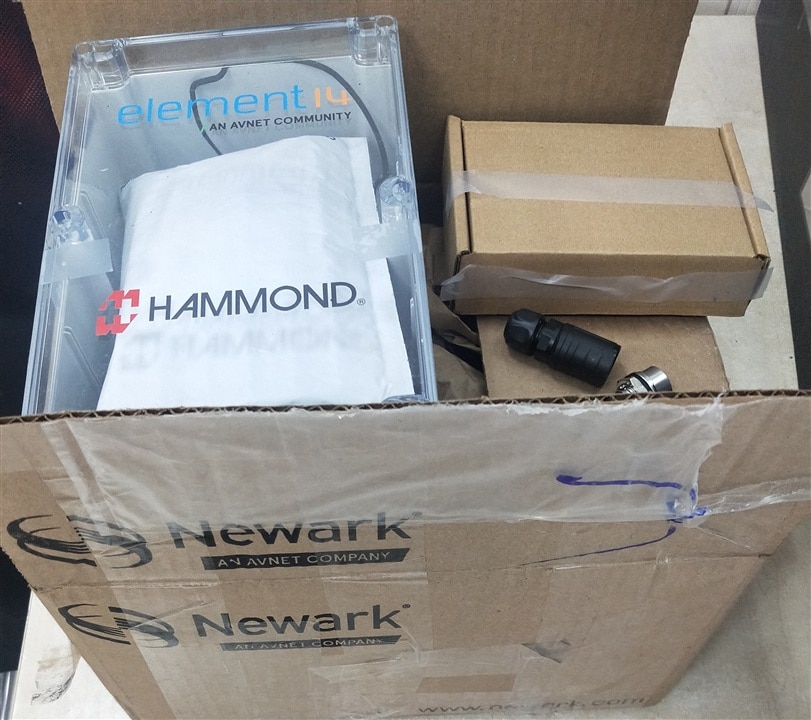
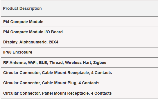
I have received this experiment kit. This unboxing blog is about to show what is in this surprising kit.

and
as of

2. IP68 Enclosure
2.1 The HAMMOND IP68 Enclosure
With reference to 1554VA2GYCL - Hammond Mfg, here is key parameters
- Exterior size of W x H 9.4 in x 6.3 in x 3.5 in(239 mm x 160 mm x 89 mm)
- Inner size for Max. P.C. Board Length of 145.5mm and Max. P.C. Board Width of 226.82mm
- Shipping Weight 1.35 lbs (0.61 kg)
- IP Rating IP68
2.2 There are four parts, one base box, one front lid, one circular seal strip and six fixing screws.
The front panel of the lid with colorful brand mark of HAMMOND and Element14,
2.3 The circulart seal strip in the box,
The circular seal strip is very keen in this design,
exactly fit the shape and size of the slot in front lid,
press the seal strip into the slot in front lid,
The curve and shape fit exactly
Be aware, the cross section of the seal strip is square, so it may twist and make small turn in slot,
So, sort the seal strip well when fitting into the slot.
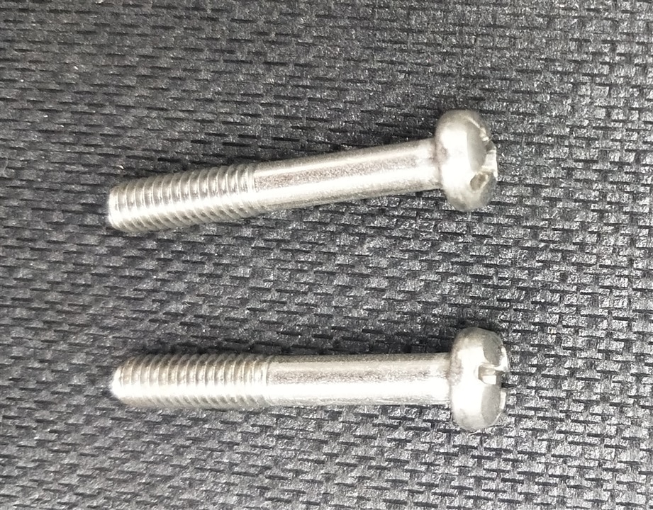
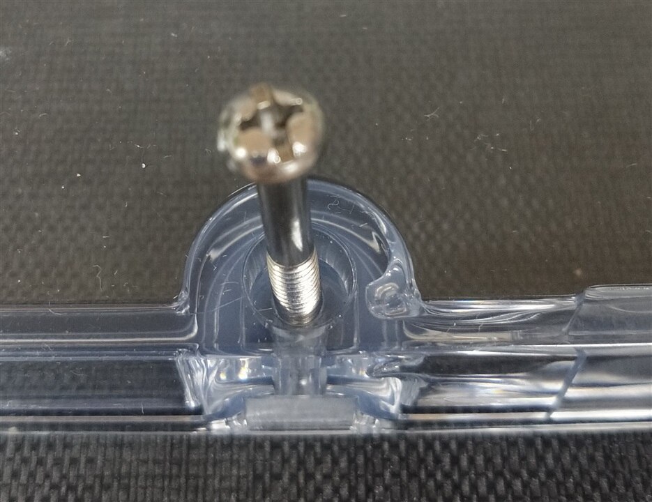
2.4 Six fix screw
The screw is design for anti-slip when fixing into the screw hole


2.5 Accessery
There are neccessary accesseries for this IP68 Enclosure, to hold PC board. I plan to build by myself, so the drawing 1554VA (farnell.com) is very useful.
3. Circular connectors
3.1 The circular connectors
The document 2688495.pdf explain specification of the connectors with minor difference, here is IP67 instead of IP68. I shall go further with IP67 and IP 68 /IP 69 in next blog.
Here are Circular Connector, Panel Mount Receptacle, 4 Contacts
and Circular Connector, Cable Mount Plug, 4 Contacts.
There is no Cable Mount Receptacle in this kit. Even so, that is enough for the proposed project of Extreme Environment Home Assistance Sensors. Since the connectors can connect tightly,
Both the Panel Mount Receptacle and Cable Mount Plug can be dismentled.
Panel Mount Receptacle need special tool to remove the small steel tighten ring, so let it be for now.
Cable Mount Plug can be dismentled, showing clearly the water-tight design,
3.2 Mounting the circular connectors
There is one pre-drilled hole for circular connector
The Panel Mount Receptacle connector can be fixed through the hole
The plug the Cable Mount Plug,
4. The Raspberry Pi 4 Computer Module and I/O board
4.1 The Respberry Pi 4 Computer Module with IP board is used as SBC in this experiment,
4.2 Pi CM4 IP board Pi CM4 lite with zero onboard eMMC
With reference to Raspberry Pi Compute Module 4 IO Board , the main features for the Pi CM4 for are,
• Accepts the complete range of CM4 modules, in this case CM4 lite with zero eMMC
• External +12V PSU
• 2 × Full-size HDMI 2.0 connectors
• 1 x Gigabit Ethernet RJ45 with POE support
• 2 × USB 2 Socket, with header for two more sockets
• Micro USB socket for updating the CM4
• Micro SD Card socket
• 1 x PCIe 2.0 Gen 2 socket
• Standard Fan connector
• External power connector (+5V, +12V)
• 2 × MIPI DSI display FPC connectors (22pin 0.5mm pitch cable)
• 2 × MIPI CSI-2 camera FPC connectors (22pin 0.5mm pitch cable)
• Raspberry Pi HAT connector
• RTC with Battery socket and ability to wake up CM4
• Jumpers to disable features, e.g Wireless, EEPROM writing
4.3 Pi CM4, part No. CM4104000
With reference to document 3164619.pdf , the specification of Pi CM4 lite are,
Size of 55 mm × 40 mm
Processor:
- • Broadcom BCM2711 quad-core Cortex-A72 (ARM v8) 64-bit SoC @ 1.5GHz
- • Memory: 4GB LPDDR4
- • Connectivity: • Optional wireless LAN, 2.4GHz and 5.0GHz IEEE 802.11b/g/n/ac wireless, Bluetooth 5.0, BLE with onboard and external antenna options
- • Onboard Gigabit Ethernet PHY supporting IEEE1588 • 1 × USB 2.0 interface • PCIe Gen 2 x1 interface
- • 28 GPIO signals
• external eMMC (for use only with Compute Module 4 variants without eMMC)
- Video:
- • Dual HDMI interface (up to 4Kp60 supported)
- • 2-lane MIPI DSI display interface
- • 2-lane MIPI CSI camera interface
- • 4-lane MIPI DSI display interface
- • 4-lane MIPI CSI camera interface Multimedia: H.265 (4Kp60 decode); H.264 (1080p60 decode, 1080p30 encode); OpenGL ES 3.0 graphics
Input power: 5V DC
4.4 Pi CM4 is similar with Respberry Pi 4B in many features, and share same software image files. Detail of power-up experiment shall be put in further blogs on Home Assistant Operation System(HAOS).
5. The Antenna
With reference to MOLE-S-A0010974943-1.pdf, this molex antenna shall be used in Pi CM4 as external antenna,
This is dual band 2.4/5GHz Balanced Flex Antenna , supporting full Protocol as BLE, BT, Thread, Wi-Fi, Wireless Hart, and Zigbee, with impressive electrical specification,
- Peak Gain (dBi) 3.2 @ 2.4 GHz, 4.25 @ 5 GHz
- Return Loss - S11 (dB) < -10
- Total Efficiency >78% @2.4 GHz, >79% @ 5 GHz
6. The LCD module
Another special part is the LCD module, with reference to MC42005A6W-SPTLYI-V2 (farnell.com)
This is Midas LCD 20x4 Panels with I2C interface. Unlike normal 16x2 LCD panel ,this can support more character and show rich information.
This LCD panel may not used in proposed project of Extreme Environment Home Assistance Sensors. And I shall test the LCD first then decide whether include it in the project.
7. Summary
The experiment kit are all in good mode on-the-go for my project right away.
While I still need more electronic parts to make the whole project, such as ESP32 development board or Raspberry Pi Pico Board and environmental sensors. I shall explain them in detail in following blogs.
