element14 Community
element14 Community
    Register Log In
  • Site
  • Search
  • Log In Register
  • Community Hub
    Community Hub
    • What's New on element14
    • Feedback and Support
    • Benefits of Membership
    • Personal Blogs
    • Members Area
    • Achievement Levels
  • Learn
    Learn
    • Ask an Expert
    • eBooks
    • element14 presents
    • Learning Center
    • Tech Spotlight
    • STEM Academy
    • Webinars, Training and Events
    • Learning Groups
  • Technologies
    Technologies
    • 3D Printing
    • FPGA
    • Industrial Automation
    • Internet of Things
    • Power & Energy
    • Sensors
    • Technology Groups
  • Challenges & Projects
    Challenges & Projects
    • Design Challenges
    • element14 presents Projects
    • Project14
    • Arduino Projects
    • Raspberry Pi Projects
    • Project Groups
  • Products
    Products
    • Arduino
    • Avnet & Tria Boards Community
    • Dev Tools
    • Manufacturers
    • Multicomp Pro
    • Product Groups
    • Raspberry Pi
    • RoadTests & Reviews
  • About Us
    About the element14 Community
  • Store
    Store
    • Visit Your Store
    • Choose another store...
      • Europe
      •  Austria (German)
      •  Belgium (Dutch, French)
      •  Bulgaria (Bulgarian)
      •  Czech Republic (Czech)
      •  Denmark (Danish)
      •  Estonia (Estonian)
      •  Finland (Finnish)
      •  France (French)
      •  Germany (German)
      •  Hungary (Hungarian)
      •  Ireland
      •  Israel
      •  Italy (Italian)
      •  Latvia (Latvian)
      •  
      •  Lithuania (Lithuanian)
      •  Netherlands (Dutch)
      •  Norway (Norwegian)
      •  Poland (Polish)
      •  Portugal (Portuguese)
      •  Romania (Romanian)
      •  Russia (Russian)
      •  Slovakia (Slovak)
      •  Slovenia (Slovenian)
      •  Spain (Spanish)
      •  Sweden (Swedish)
      •  Switzerland(German, French)
      •  Turkey (Turkish)
      •  United Kingdom
      • Asia Pacific
      •  Australia
      •  China
      •  Hong Kong
      •  India
      •  Japan
      •  Korea (Korean)
      •  Malaysia
      •  New Zealand
      •  Philippines
      •  Singapore
      •  Taiwan
      •  Thailand (Thai)
      •  Vietnam
      • Americas
      •  Brazil (Portuguese)
      •  Canada
      •  Mexico (Spanish)
      •  United States
      Can't find the country/region you're looking for? Visit our export site or find a local distributor.
  • Translate
  • Profile
  • Settings
Experimenting with Flyback Transformers
  • Challenges & Projects
  • Design Challenges
  • Experimenting with Flyback Transformers
  • More
  • Cancel
Experimenting with Flyback Transformers
Blog Blog 1: Transforming my understanding of flyback transformers, one hack at a time
  • Blog
  • Forum
  • Documents
  • Polls
  • Files
  • Members
  • Mentions
  • Sub-Groups
  • Tags
  • More
  • Cancel
  • New
Join Experimenting with Flyback Transformers to participate - click to join for free!
  • Share
  • More
  • Cancel
Group Actions
  • Group RSS
  • More
  • Cancel
Engagement
  • Author Author: BigG
  • Date Created: 16 Dec 2023 1:47 PM Date Created
  • Views 2370 views
  • Likes 11 likes
  • Comments 12 comments
  • Transforming diagnostics and comms
  • BA60951CS
  • EXPERIMENTING WITH FLYBACK TRANSFORMERS
  • SMPS Flyback Transformers
  • bourns
Related
Recommended

Blog 1: Transforming my understanding of flyback transformers, one hack at a time

BigG
BigG
16 Dec 2023

Introduction

We all start with an idea and a plan. I started with an inkling of what flyback transformers were about, having seen common chokes being used for isolated signal coupling, and I had an itch I wanted to scratch.

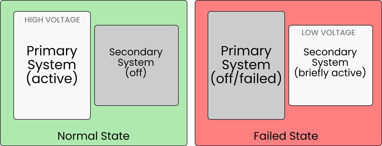
I wanted to see if I could use flyback transformers as a type of energy harvesting power source to safely power a secondary system, when it’s needed for diagnostics and communication (using something like powerline narrowband communication) after a power failure. The intended target for this type of secondary monitoring device would be high voltage AC and DC powered systems where you would need isolation. In my ignorance, I thought the flyback transformer would be suitable for this purpose. So I’m using the design challenge to prove it, either way.
image

Now having started with a plan, I took my first steps to get things started (see next sections) and that’s quickly when I realised that assumption had gotten in the way and that plan of mine would need refinement by way of some fundamental design changes.

Little did I realise that my initial interpretation of flyback transformer documentation was slightly amiss, and this was mostly down to assumption.

But then again, that’s why I like these design challenges as it takes you along a learning-by-doing (-failures) journey. I mean, where else do you get these opportunities to create SpaceX styled magic smoke?

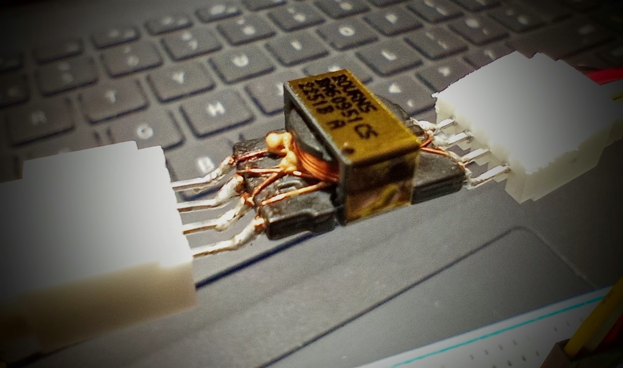
And here’s the result… but more on that “failure-on-purpose” stunt later…
image

And, I’m sorry to say folks… yet again, I never had reporters and TV crew on hand to capture the event. So, you’ll just have to take my word for it. It was pretty spectacular.

So, here’s how I’ve started this design challenge journey.

First step - check my assumption for AC power operation

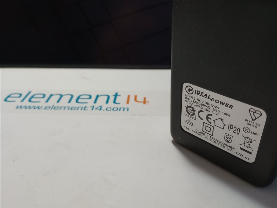
In my application I had requested the AC power supply to allow me to test out my AC options and I received a 24VAC power supply from IDEAL Power, which looks “ideal” for my purposes.
image

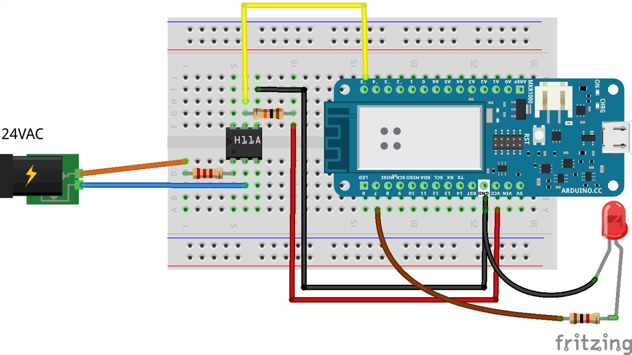
Now with AC voltage, I knew I would have to check for zero crossing and measure the timing in order to determine if there was a power failure. So as my first step I decided to check that I could reliably measure the zero crossing of an AC power supply.

I knew optocouplers were commonly used for this purpose and when watching a video on YouTube I spotted a H11AA1 opto-coupler being used. This has a bi-directional input, making it suitable for applications requiring detection or monitoring of AC signals.

The circuit looked nice and simple to build:
image

And here’s my first video demo. As you might guess from the voice-over, this video was taken well before I had even tested a single flyback transformer…

You don't have permission to edit metadata of this video.
Edit media
x
image
Upload Preview
image

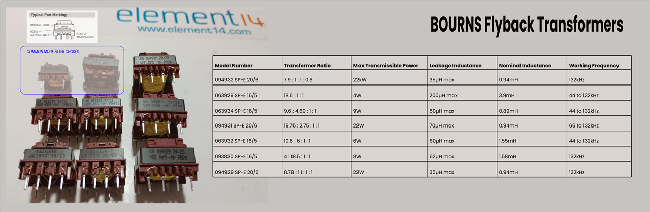
Anyway, as far as I was concerned, this was the start I was looking for. It’s given me confidence to move forward on the AC side, and I now plan to test a number of the flyback transformers available in my kit to see how much power I will be able to get for my application.

Looking at the kit, I think I have quite a few to choose from.
image

Second step - check my assumption for DC power operation

Buoyed by the success of my zero crossing detection circuit, I then moved onto testing my assumptions of how I could use a SMPS flyback transformer with DC power.

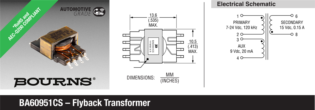
For this experiment I used the BA60951CS flyback transformer provided in the kit.
image

Reading through the general specifications provided in the datasheet, I could see that this flyback transformer accepts a primary input voltage between 7 to 24V, and based on the different turns ratios for auxiliary (1.27) and secondary (0.77) coils delivers an auxiliary voltage of approx. 9V and a secondary voltage of approx. 15V. What is not clear to me in the datasheet is this so-called “working voltage” of 800V, but as I have no plans to use really high voltages I will leave that as an open question.

There were also two other specifications where I was struggling to understand the context. Namely rated primary current (1.4A) and the frequency (120kHz).

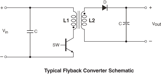
So I decided to just try out a minimal circuit design that were shown in the beginners guides to flyback converters. Namely:

Figure 1 in the Coilcraft beginners guide...
image

And figure 1 in the Kynix explanation on flyback transformers...

image

But, instead of using a MOSFET, I chose to use a momentary push button to manually/randomly control switching. Whilst I discovered that this option did not really work at all, it did reveal some interesting behaviour when you had debounce. It was slowly dawning on me as to why switching frequency matters, but this took a good deal of convincing.

I was still trying to understand the behaviour as described in the Coilcraft article:

The basic flyback cycle includes the following portions:

  1. When the FET (Field Effect Transistor) SW is closed (ON), current is conducted through the transformer primary. This sets up a magnetic field in which energy is stored in the core. The combination of winding polarity (identified by the polarity dots) reverse biases the output diode to ensure that no energy is transferred to the secondary (load) when the switch is closed. During this portion of the cycle, current in the primary is ramping up over time to store energy (= ½LI2).
  2. When the FET is opened (OFF) the magnetic field collapses, transferring the stored energy to the secondary winding and, ultimately the load. At the close of the switch, current in the secondary is at its peak and ramps downward as the stored energy is transferred to the load.

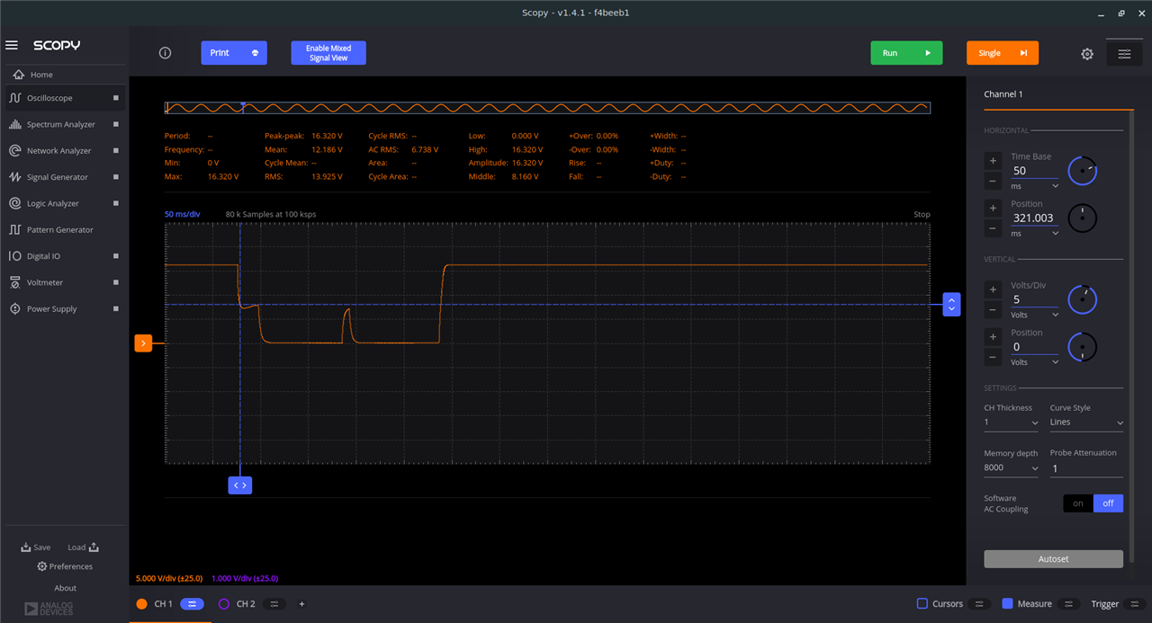
I somehow had thought that you could get the switch closed (ON) indefinitely. When testing, all I could see on my oscilloscope was that the primary voltage drops… as shown here when I momentarily keep the pushbutton on.
image

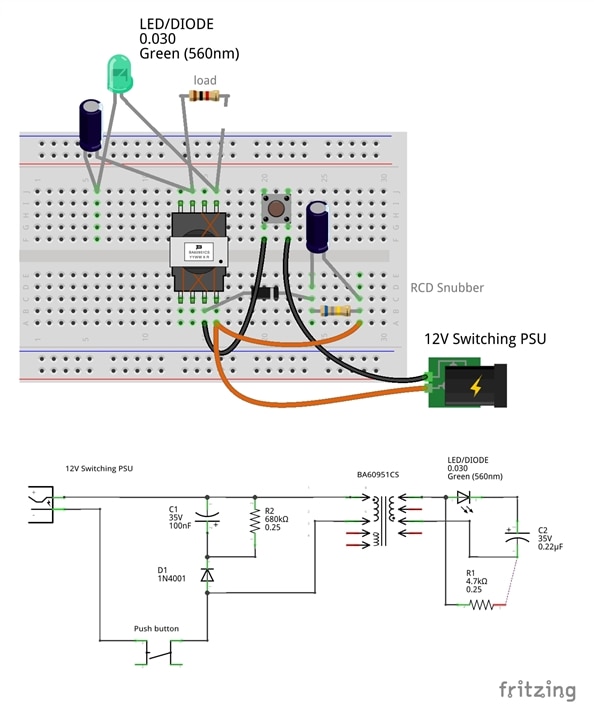
In fact, I was convinced it was circuit related. So, I then added a RCD snubber on the primary side, thinking this would solve matters. It did to some degree but not that much.
image

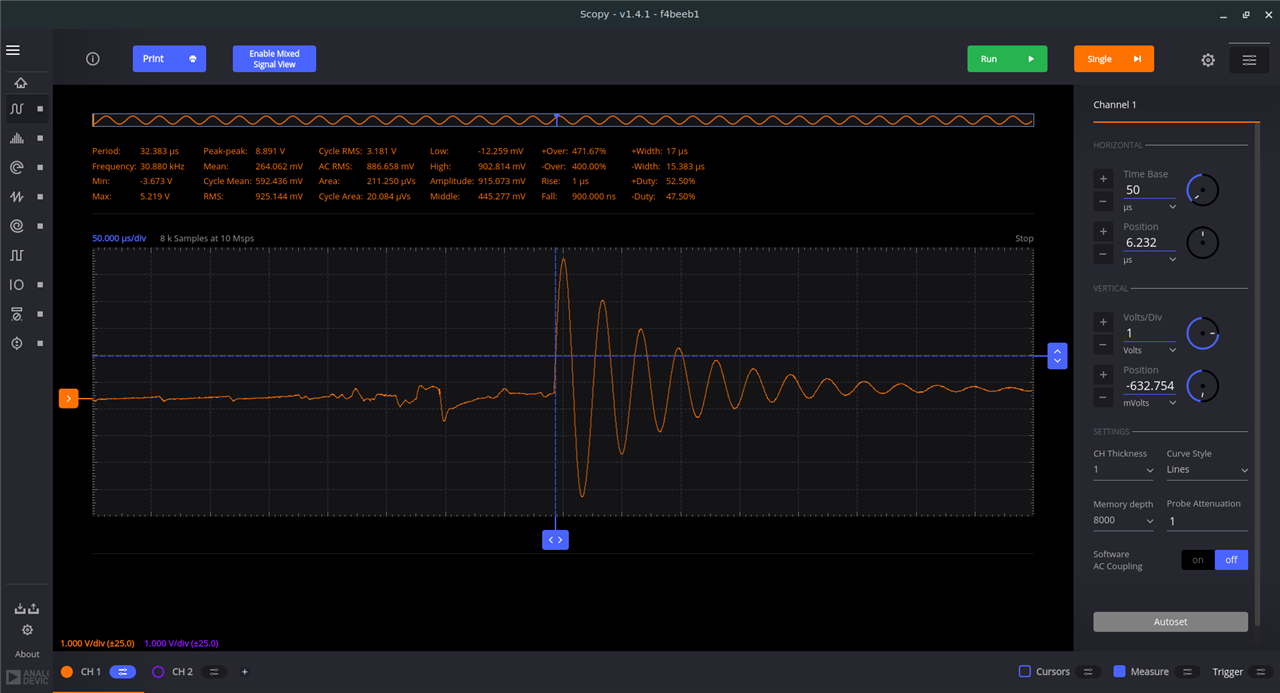
Here in my circuit I used an LED instead of a standard diode on the secondary side to help visualise matters (I relied on the fact that voltage and current flow was momentary).

You don't have permission to edit metadata of this video.
Edit media
x
image
Upload Preview
image

I could now observe interesting behaviour during button debounce on the secondary side, as shown, but it still not help my understanding of the fundamental concepts when using DC power. This is the secondary voltage through the diode:
image

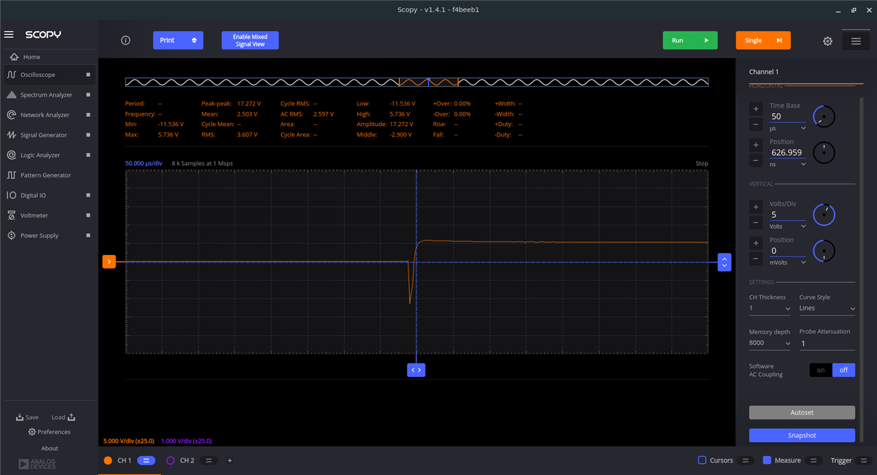
And this is the voltage across the capacitor (when there is no load - open circuit).
image

It still just did not make sense to me.

So, I took matters to the extreme, where I hooked up a 6A 15V power supply to the primary coil and held the switch on... and as mentioned in my introduction, this did not end well.

Anyway, I have finally grasped the meaning of “During this portion of the cycle, current in the primary is ramping up over time to store energy (= ½LI2)”.

And... I've also ordered another BA60951CS to continue.

Next steps

As to my next steps for this design challenge. Well, I am happy with AC but for DC I am now preparing a radical rethink of my design concept.

You’ll just have to wait till my next blog to find out…

  • Sign in to reply

Top Comments

  • shabaz
    shabaz over 2 years ago +1
    At least a smoking transformer is (sometimes) better than a exploding capacitor : ) Most datasheets will vary when it comes to transformers, but in the case of that particular one, the things that would…
  • jc2048
    jc2048 over 2 years ago +1
    With a capacitor, the energy storage is potential energy. It persists until there is a path so that the charge (that you did work to separate) can recombine (where you get the energy back). With an pure…
  • BigG
    BigG over 2 years ago in reply to javagoza

    Thanks these graphs are great and useful to help explain the behaviour. The Digilent Analog Discovery 2 having an impedence analyser is a very useful feature.

    • Cancel
    • Vote Up 0 Vote Down
    • Sign in to reply
    • More
    • Cancel
  • BigG
    BigG over 2 years ago in reply to jc2048

    Putting my mechanical engineering hat on, I can relate to potential and kinetic energy. That's a great explanation. Now makes better sense. Thanks.

    Yes, I did wonder about the choice of diode in the snubber. The diode chosen was just one I found in a tub of loose components on my desk and used on the basis of "gotta start with something". Thanks for that explanation. It's really helpful.

    • Cancel
    • Vote Up 0 Vote Down
    • Sign in to reply
    • More
    • Cancel
  • jc2048
    jc2048 over 2 years ago

    With a capacitor, the energy storage is potential energy. It persists until there is a path so that the charge (that you did work to separate) can recombine (where you get the energy back). With an pure inductor, it's more like kinetic energy. It builds whilst the current is increasing. Is held whilst the current is constant, and then released when you remove the voltage that's driving the current (the coil generates an emf to keep the current flowing as the field winds down). The energy absolutely has to come out of the magnetic field - if you don't provide a path at all, the inductor will create one, generating a voltage so high that it will breakdown a semiconductor or the air.

    So the energy storage is small scale and temporary. In a SMPS, it all adds up because you take the small dollops of energy that come out on each switching cycle and store them on a capacitor to power a circuit for a short period of time. Do it 120,000 times a second and there's a reasonable effect to it.

    If we ignore the secondary just for a moment, the primary circuit you've got there is a simple boost circuit - at this point people will tell me it's 'flyback' or 'buck-boost', but it's easier to understand as a boost. The secondary winding is another coil that shares the same magnetic flux as the primary [the core sees to that, as it channels most of the flux in a magnetic circuit within the confines of the material]. That means the secondary will respond to the changes in flux, just as the primary does, except there is a scaling factor if there is a different number of turns. When the switch turns off, the energy comes out of either the primary [as with a simple single-inductor boost circuit] or the secondary [which is probably what we want], depending on where a suitable path lies.

    There are two consequences of all that you need to consider.

    Firstly, if you have fixed switching without any control and don't have a load on the secondary, it will keep pumping up the output capacitor voltage as more and more dollops of charge end up there. It will limit at some point. Either something will break down, or the primary path will suddenly become available limiting further movement. But if you want an accurate voltage at the ouput you either need active regulation of the whole converter or have a device on the output that can absorb the excess energy whilst limiting the voltage (i.e. zener - hugely wasteful because the zener will have to take the energy if your circuit doesn't want it and everything is running at full tilt all the time).

    There are various schemes for control and regulation. PWM is one. A fixed on-time and variable off-time [so not constant frequency] is another. Monitoring the primary current [leading to variable on-time] is another.

    Secondly, if you have that arrangement with the 1n4001 ordinary diode and snubber on the primary, I think you'll find that it takes all the energy and you won't achieve what you want at the secondary. You'll probably need a zener there so that the secondary gets first go and the diode/snubber is only cutting off any transients there.

    Hopefully I've mostly got that right. I'm sure someone will correct me if it's wrong in any detail.

    • Cancel
    • Vote Up +1 Vote Down
    • Sign in to reply
    • More
    • Cancel
  • javagoza
    javagoza over 2 years ago in reply to shabaz

    Hi  BigG Thank you for sharing your experiences and this notice to Mariners. I am still working in a blog on the characterization of some of the transformers of the Kit. This image of my impedance analyzer, for the Digilent Analog Discovery 2, shows the impedance, inductive and resistive to open circuit for a wide range of frequencies for the three windings of that transformer, the BA60951CS - Flyback Transformer. Zoom to visualize it better.

    You can see well the behavior described by  shabaz  of the inductance relationship with the frequency.

    image

    • Cancel
    • Vote Up 0 Vote Down
    • Sign in to reply
    • More
    • Cancel
  • BigG
    BigG over 2 years ago in reply to shabaz

    Shabaz you are indeed correct... I had initially thought that energy is held inside the coil as a capacitor would store energy. Clearly not the case... but that's what experimentation is all about.

    I was not sure of this, so decided to confirm either way... "The Isat isn't a maximum current that the transformer will consume, but is the maximum current that should be provided (ideally less). Once the Isat value is allowed to exceed, current shoots up, and can cause the smoke. That occurs because beyond Isat, the inductance decreases, due to properties of ferrite material."

    I had this very same question. I initially thought to control current using resistance but this did not work as intended..."The question is, how can the Isat value be not exceeded, and the answer is by only allowing current to flow in the primary until it approaches that value (it ramps up), and then disconnect."

    Anyway thanks for the explanation using the formula to explain frequency. I've been pondering over this for ages.

    I am now thinking of using a set frequency on the primary side to switch a MOSFET. So, I hope to apply a similar design principle to AC where if I can detect this set switching frequency then all good. If no voltage after set frequency then failure condition.

    The software I am using is called SCOPY, which comes with the Analog Devices ADALM2000 module. It's rather handy... and it works on Linux, which most don't.

    • Cancel
    • Vote Up 0 Vote Down
    • Sign in to reply
    • More
    • Cancel
<>
element14 Community

element14 is the first online community specifically for engineers. Connect with your peers and get expert answers to your questions.

  • Members
  • Learn
  • Technologies
  • Challenges & Projects
  • Products
  • Store
  • About Us
  • Feedback & Support
  • FAQs
  • Terms of Use
  • Privacy Policy
  • Legal and Copyright Notices
  • Sitemap
  • Cookies

An Avnet Company © 2026 Premier Farnell Limited. All Rights Reserved.

Premier Farnell Ltd, registered in England and Wales (no 00876412), registered office: Farnell House, Forge Lane, Leeds LS12 2NE.

Follow element14

  • X
  • Facebook
  • linkedin
  • YouTube