I've been called weird a fair number of times for carrying a multimeter or screwdriver in my backpack to a social outing. I think that's just basic everyday stuff to carry around, but people just don't get it. Anyway! I decided that instead of trying to convince them I'm not weird, I'm just going to go heavy on the weird, and what better for that than to bring chaos with me wherever I go? I truly mean chaos!
A bit over a year ago I was having a blast learning about analog computers and dynamical systems, and I wanted to do a presentation on that for my differential equations class, so the only reasonable thing to do was to build one of the chaotic attractor circuits out there, and what easier than Chua's circuit?
I present to you, the ugliest analog computer:
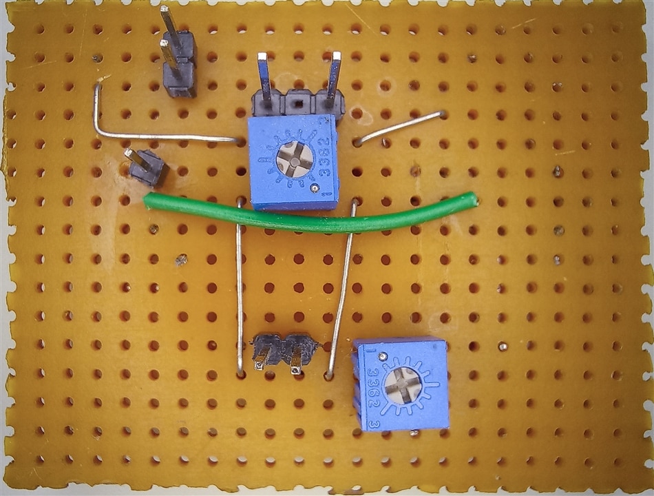
And it gets worse:
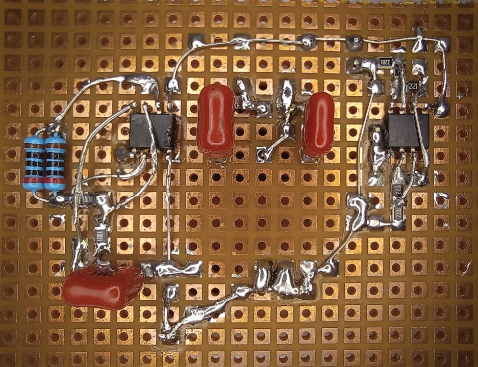
This was built right before class, and while usable for the class, the horrible job i did (or failed to do) at making it presentable has been haunting me ever since, and now is the time to right that wrong and while I'm at it, also integrate it with a power supply of its own.
This video shows the circuit in action for those interested:
So now that we know what the application will be, let's see what the requirements are.
From the schematic we can see this circuit requires positive and negative supply rails:
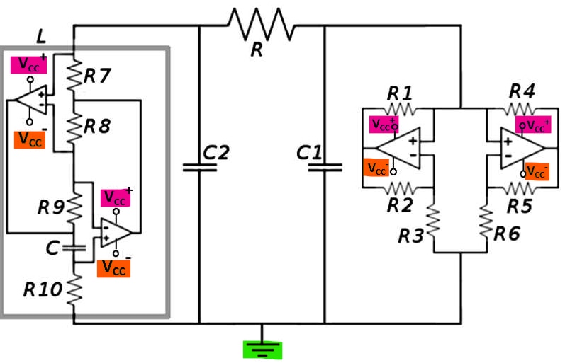
This schematic was taken from chuacircuits.com and it's the same I built.
The operational amplifiers used for the gyrator and Chua's diode can use a wide range of voltages, up to +/- 18V but I'll go for a +/- 9V supply. We saw that the real life implementation provides us with a slightly lower output voltage than what we design for when assuming ideal components, so to take this into consideration, I'll choose +/- 12V as the target, and now we have the voltage requirement out of the way!
and to get an idea of the current I put the multimeter in series with both the positive and negative rails, and got about 2.3mA on each rail when the circuit goes chaotic:
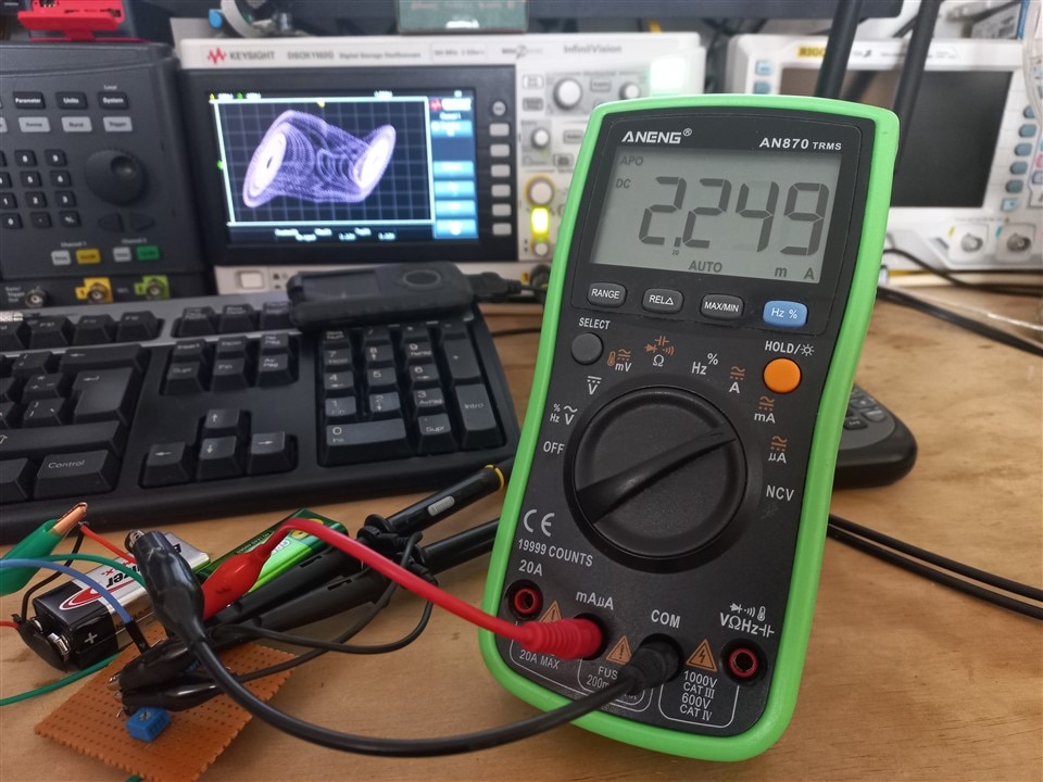
This low current might be an advantage or it might turn out to be problematic, as the duty cycle might end up being too low to be reasonably achieved and I'm not going to be regulating the output using feedback, but we'll see!
Now knowing both the current and voltage requirements, it's time to figure out which part is best suited for the task.
We already looked at the BA60951CS
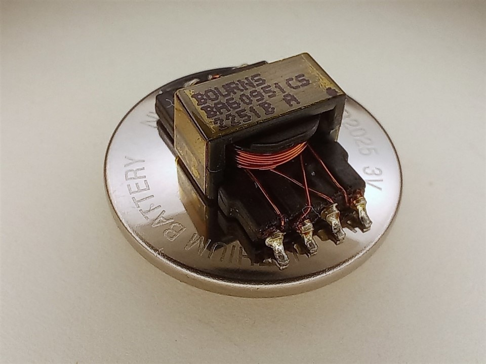
Very cute!
We only looked at the primary and secondary windings, but this transformer also has an auxiliary winding. Unfortunately for us, with a turns ratio between primary and secondary of 0.77, and between primary to auxiliary of 1.27, no two windings are symmetric, and that's a requirement.
Part Selection: The game!
Our chaotic attractor may embrace the apparent randomness of the universe, but when it comes to its power rails, it sure does know what it wants.
Today, one lucky transformer will be chosen to embark on an adventure with our chaotic attractor to perform the energy transfer dance for all of its unspecified MTBF, one electrifying tango!
We'll see what each contestant is made of, and we'll put that to the test.
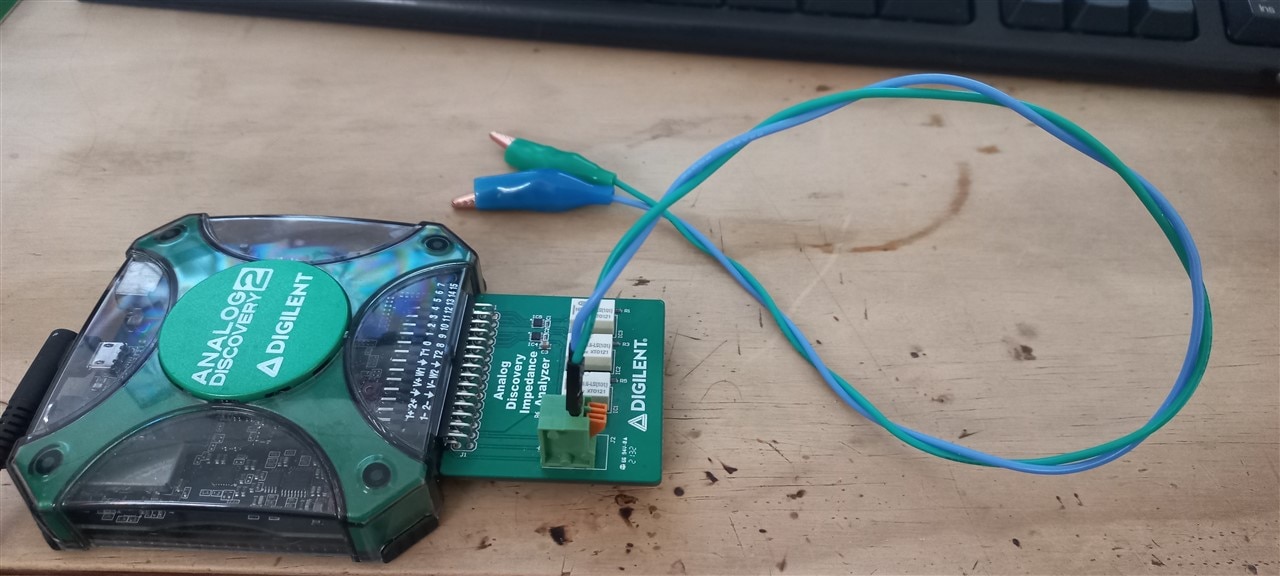
The test procedure will be performed by the Analog Discovery 2's Impedance analyzer, and we'll find out how truthful they are about their specifications. This time the impedance analyzer will be equipped with these less than ideal long leads, but this will be somewhat compensated for, so we still expect it to perform a reliable scrutiny of our contestants:
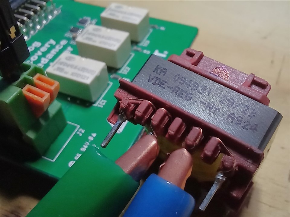
The contestants in the first group have an uncanny resemblance between each other, so much so that a single picture will suffice to know how any of them looks like. They are the:
094929, 094931 and 094932
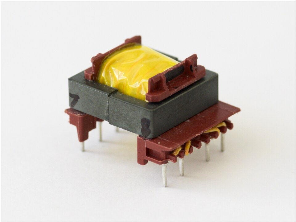
This group is the E 20/6 lineup of the Smart Power Transformers set, and brings home the highest power rating from the entire kit, with each of them being rated for a maximum of 22W.

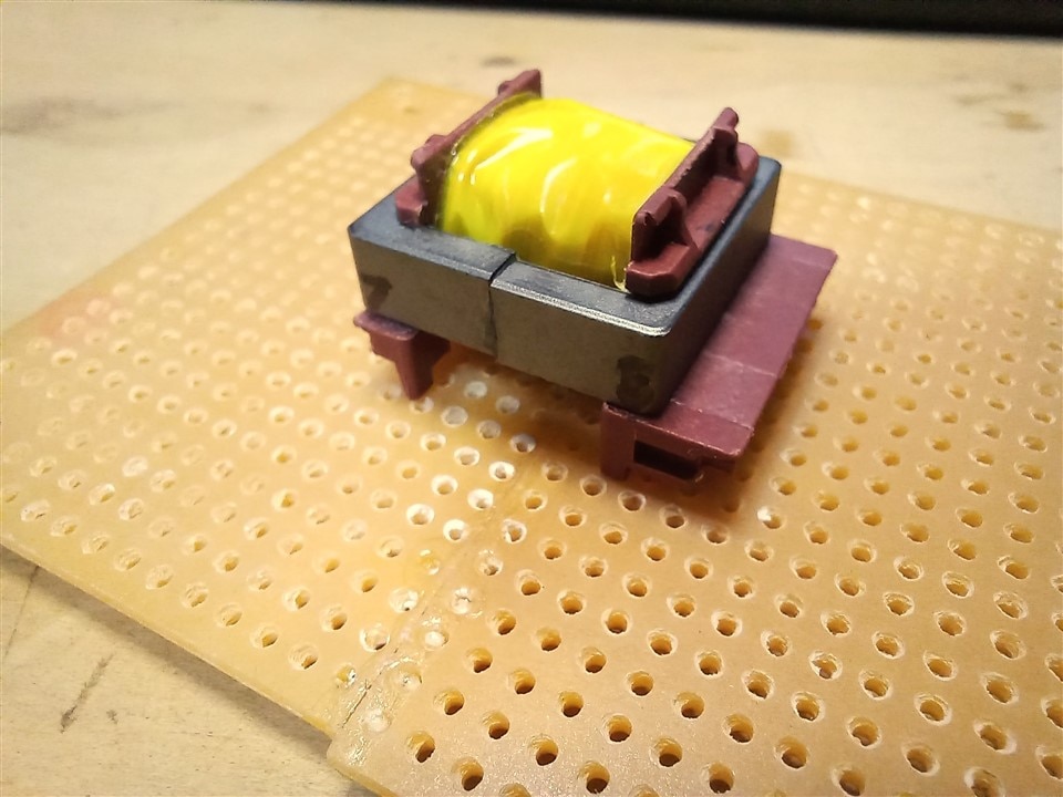
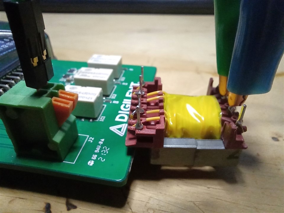
These transformers, while using a close to standard 2.54mm prototyping-friendly 2.5mm pin spacing, have the pins of the primary and secondary staggered:
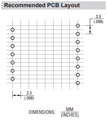
The pins in this configuration won't fit in a standard 2.54mm grid, but for prototyping, we can easily get around that minor inconvenience by splitting a board then gluing it back together like this:
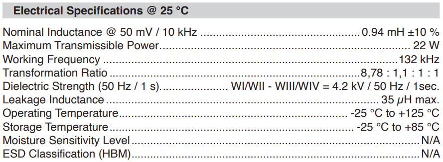
094929 tells us this about itself:
And it's schematic looks very promising:
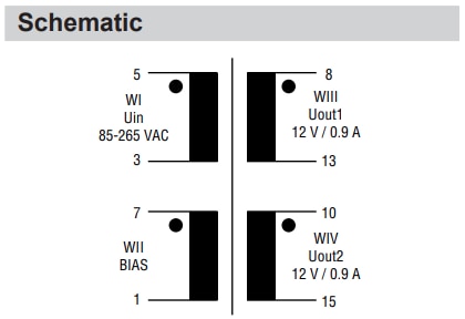
Our first contestant is going in strong. It has two 12V windings rated at the same current, which means they must be identical, and not only that, it has an auxiliary winding very close in number of turns. For our current requirements, we could use this auxiliary winding as our primary and we're set! But let's not chant victory yet, 094929, it's time to verify that what you tell us is true.

Just what it told us. Nothing like an honest contestant. Our chaotic attractor is looking at this one with much interest!
Next up:
094931 shows us what it's got:
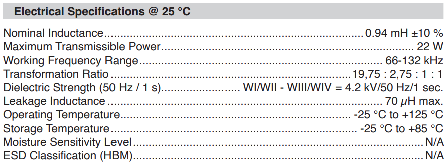
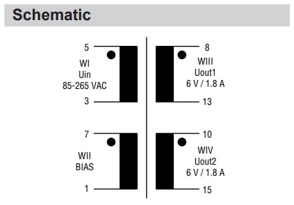
This contestant also brings symmetrical secondaries to the table, and while rated for 6V only, and having an auxiliary winding with a turns ratio of 2.75 with respect to them, we learned that turns ratio isn't all when it comes to determining the output voltage of our converter. Still, this is a harder offer to accept, considering our chaotic attractor has already seen an almost perfect match. Will any of our other contestants challenge the 094929? Is this contestant also being true to its specifications?
Let's see!

Another honest contestant, very nice to see that. Also a potentially good candidate for our application.
And our final contestant in this group:
094932 First to bring something different to the table:
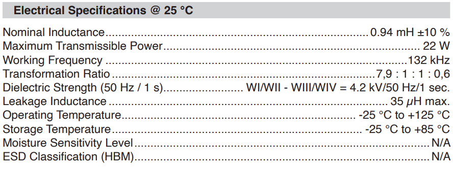
This transformer is the first in the Smart Power Transformers series to have an asymmetric set of secondary windings. While having two different voltages from the same converter can come in handy, for our application, that won't do. But there's one interesting bit which may result in our chaotic attractor considering it after all! The auxiliary winding has a 1:1 relationship with one of the secondaries, and the other secondary being lower than those two might come in handy. Low input voltage, anyone? who knows what our chaotic attractor might have to say about that.
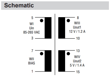
No surprises with the schematic, now let's see how close its parameters are to the spec sheet:
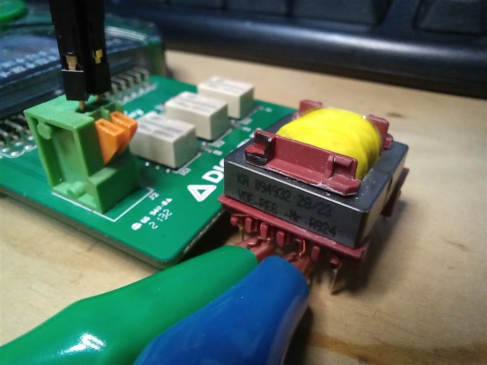

All within spec, perfect!
This group presented us with strong contestants, but now it's time to look at group number two!
063934 and 093830
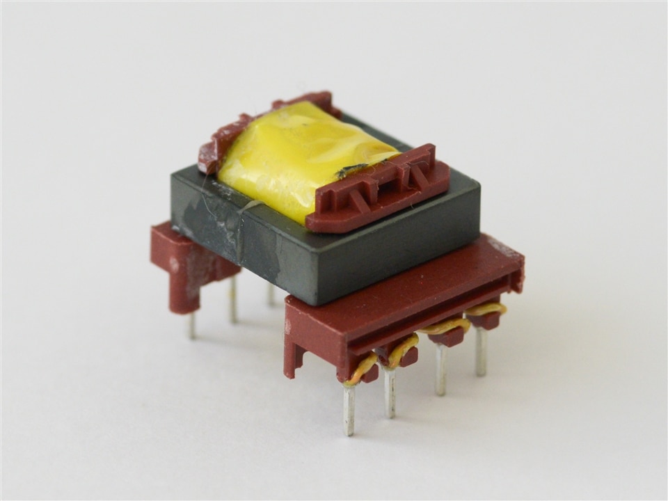
These are one half of the E 16/5 lineup of the Smart Power Transformers set. They are a bit smaller than those in the previous group, and are also designed for lower power. The two in this group (highlighted in green) are capable of handling about 9W of power, which would be more than plenty to satisfy our chaotic attractor's requirements. These transformers don't come with auxiliary windings but use instead shield windings. What i could find on shield windings is that they are used for EMC purposes and not as a regular winding, so this might rule out their use in our application.

These transformers use a less prototype-friendly pin pitch of 3.81mm, and the primary and secondary pins are also staggered, with the middle 2 pins on the secondary side being 5.08mm apart:
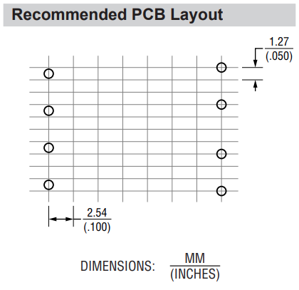
Playing around with these using standard prototyping PCBs and breadboards may not be the easiest task, but let's see if their electrical characteristics can compensate for that and gain the favour of our chaotic attractor.
First, let's look at the
063934
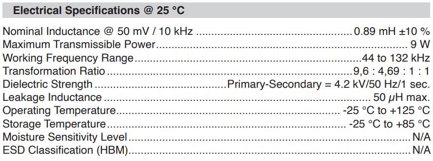
While the electrical specifications look promising, the schematic reveals one thing about the windings:
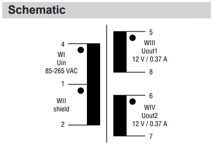
The primary and shield windings share a common pin, but other than that, this contestant has symmetrical secondaries, which would be useful in our application.
And now, since we can't blindly trust the datasheet, It's time to see how it measures:
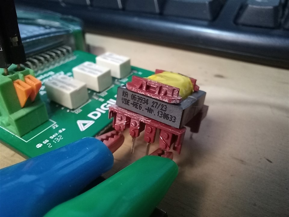

Well, it not only meets its specifications, the leakage inductance is surprisingly low on this one. I thought it was a fluke, so I re-seated the shorts and measured a few more times, but got similar results each time. That's nice.
The second and final contestant from this group is the
093830
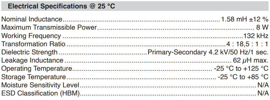
A few curious things to note are the significantly higher primary inductance, and the fact that the ratio is given with the shield winding first. I tried to find information that would explain why this one is specified like that, but couldn't find anything.
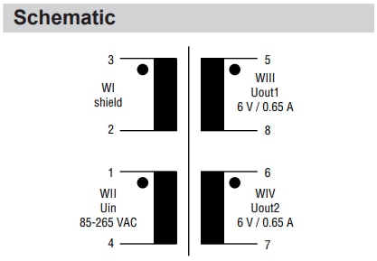
The schematic also shows the shield were we found the primary in the other transformers. This contestant is a wild one! Chaotic enough for our chaotic attractor?... Anyway, let's see if those specifications match reality.
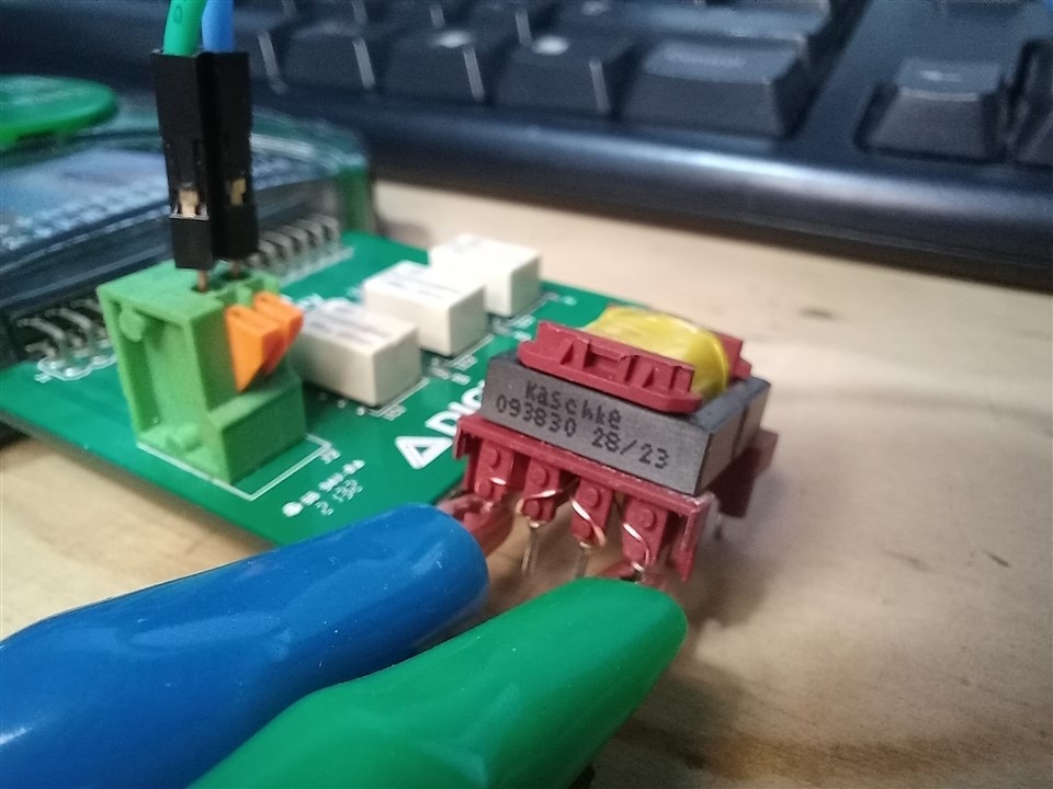

Another contestant perfectly within spec! just lovely to see that.
And now, it's time to see the final group of contestants. They are:
063932 and 063929
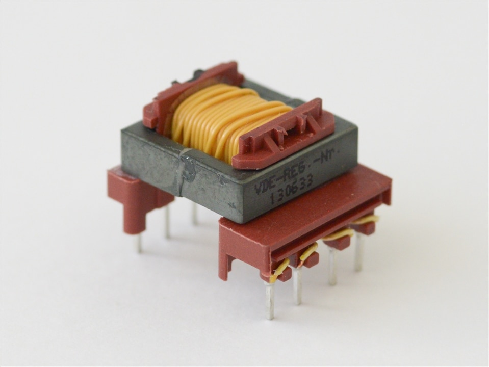
They are the other half of the E 16/5 lineup of the Smart Power Transformers set (highlighted in blue) and also the final two contestants. They are the lowest rated when it comes to power handling capabiilities, with ratings of 3 and 6W, but dielectrically speaking, they are just as strong as all the others, providing safe and reliable isolation between the windings. Pretty impressive.

As the previous group, these have the same pin pitch of 3.81mm, and the middle two pins on the secondary side are also separated by 5.08mm.
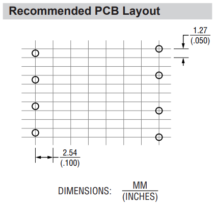
So let's meet the first contestant in this group:
063932
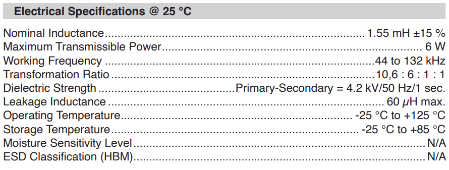
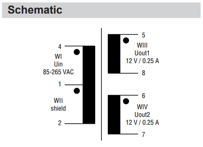
On paper this looks like a reasonable candidate, but how does it actually do when put through the test?
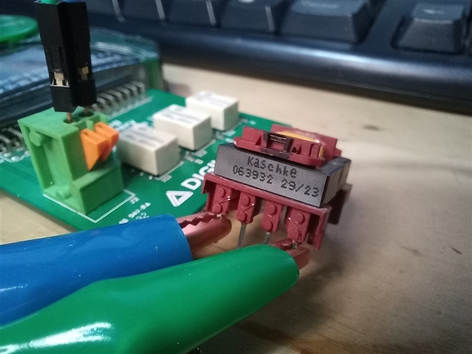

This one's primary inductance is a bit on the high side, but it's still within spec, and the leakage inductance is also well within what's specified. Great!
Now, wlecome our final contestant!
063929
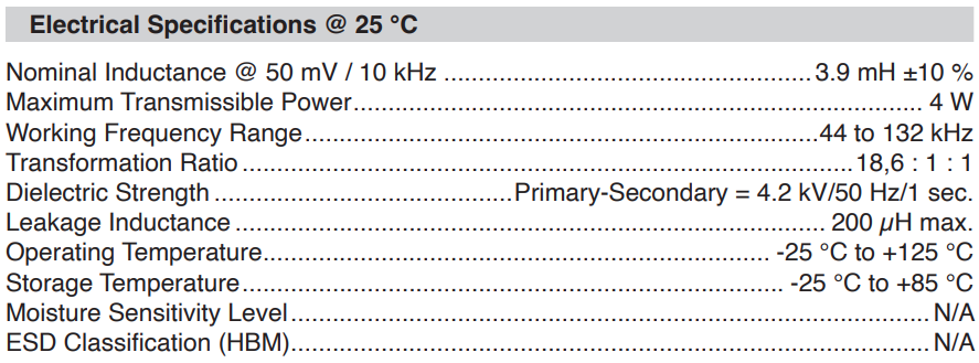
Wow! 3.9mH primary inductance. This is by far the contestant with the highest primary inductance. Will this matter to our chaotic attractor? Perhaps not as much as it being the only contestant with no auxiliary nor shield windings! Odds aren't looking good for 063929, but our application is an agent of chaos after all, so anything can happen! For now, let's look at one final transformer schematic:
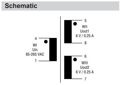
Really nice to see the symmetrical secondaries, but the lack of an auxiliary winding that allows us to drive it with low voltages is looking like a deal-breaker. Either way, let's see how close this one comes to its specifications:
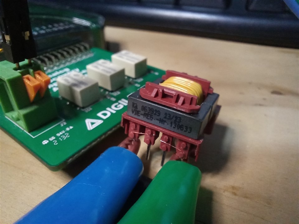
The datasheet specifies a nominal inductance of 3.9mH at 10Khz and 50mV amplitude. So let's see how it does under those parameters:

Very nice, just as expected.
And now let's look at the leakage inductance at the maximum specified operating frequency:

very surprisingly, I couldn't get it to measure under 280 μH no matter what combination of settings I tried. So sadly, our last contestant is the only one to not meet its specification. Let's be clear, the testing method used was not perfect, but after obtaining expected results for every single other transformer, it is unlikely testing inaccuracy is influencing the measurement significantly enough that this parameter erroneously measures out of spec.
Now that we've met every contestant, it's time to determine which one of them is the winner. Who will our application choose to provide its power? who will be responsible for bringing chaos into the world?...
The winner is:
The 094929!
Congratulations to our winner!
The chaotic attractor provided two very good reasons for this selection:
- The turns ratio between the secondary windings and auxiliary winding provide the most flexibility, allowing us to operate the converter with batteries and have plenty of room to adjust the duty cycle for our selected output voltages.
- The pin pitch allows us to test our converter using breadboards, which will result in faster prototyping and debugging.
Even if the full capabilities of this transformer will be under-utilized, there was no better fit for our application given the proposed requirements.
Well, that was fun. I hope you enjoyed this overview of the flyback transformers in the kit. I decided to do the kit overview with a goal attached to it, and part selection seemed like the best fit.
Next up is the final blog, where I will go through the design process of the converter for the selected application.
As always, all feedback is welcome.
Thank you!


-

DAB
-
Cancel
-
Vote Up
0
Vote Down
-
-
Sign in to reply
-
More
-
Cancel
-

Anthocyanina
in reply to DAB
-
Cancel
-
Vote Up
0
Vote Down
-
-
Sign in to reply
-
More
-
Cancel
Comment-

Anthocyanina
in reply to DAB
-
Cancel
-
Vote Up
0
Vote Down
-
-
Sign in to reply
-
More
-
Cancel
Children