In the last blog, I mainly looked at the specifications and unboxing of the transformers included in this Experimenting With Design Challenge. In this section, I’ll be tackling questions about what a “Flyback” is and doing some basic measurements of parameters using an LCR meter. Towards the end of this post, I’ll also experiment a bit with running bode plots on unloaded transformers and sending pulses through them to see just what happens.
What’s a Flyback? A Quick Primer
Early on in the contest, there were somewhat lively discussions in the original challenge thread about just what a flyback is, with one member of the forum being adamant that it is only buck, while all references I could find pointed to the converter being buck-boost. Curiously, this discussion has all magically disappeared – seemingly been deleted along with all the links I posted to literature online … so I’ve had to go looking again.

Circuit schematic from Hudson, T., Ametller, M., How to Design a Flyback Converter in Seven Steps, n.d., Monolithic Power Systems (https://www.monolithicpower.com/how-to-design-a-flyback-converter-in-seven-steps).
From hitting the books so to speak, there’s a few things to know. The first is that “flyback” as a term commonly refers to the flyback topology of power converter which utilises a flyback transformer at its heart. The flyback topology itself resembles a buck-boost converter, with the inductor replaced by the flyback transformer instead (see Flyback Regulators here). The circuit can perform buck-boost functionality by virtue of the physics of turns ratio of transformers combined with the ability to adjust duty cycle and can produce multiple output voltages given different windings on the transformer (although usually only one output can be regulated). The transformer provides primary to secondary isolation, which is a positive for safety especially when working on mains voltage. The transformer itself also contains a gap, which increases the magnetic reluctance of the transformer, allowing for increased energy storage in the magnetic field by reducing the effects of core saturation. Therefore the transformer stores energy like an inductor, unlike ordinary transformers. The reason it is called a flyback is mainly because the voltage “flies back” as the switch opens, or so I’m led to believe, but one source relates this to its use in CRT televisions instead. Such topologies are favoured for smaller converters as they are simple requiring no additional storage inductor, but really only suitable for power levels up to around 100-150W and currents up to 10A with a pulsating output. Output regulation generally requires either optocoupled feedback, a feedback winding or primary-side sensing.
In my searches, I came across this nice summary of converter topologies from Lazar Rozenblat which was quite handy. Another excellent source of information is the Texas Instruments Power Topologies Handbook, specifically Chapter 9 which details the waveforms of CCM and DCM flyback operation. There’s an overwhelming amount of formulas and math in there – I’m a little out of my depth there. Another good reference appears to be this tutorial from Monolithic Power Systems about designing a flyback converter “in seven steps”. There is a simple online simulator from Plexim as well, although the range of values that can be used is somewhat limited.
Measurements with an LCR Meter
Some of the key specifications for flyback transformers include inductance, so it seemed appropriate to try measuring them using an LCR meter.
I decided to use the B&K Precision BA6010 Battery Analyser as an LCR meter to perform some measurements. This meter is intended for use in measuring AC internal resistance for batteries and acts like an isolated 1kHz AC LCR meter. While its ranges and accuracy may not be as good as a proper benchtop LCR meter, it’s more accurate than most handheld meters.
To back this up, I decided to also use my Agilent (now Keysight) U1733C Handheld LCR Meter for higher frequency, 10kHz testing.
This should be a closer match to datasheet testing conditions, although I was not able to match the test current in all cases as the meter decides what current to use.
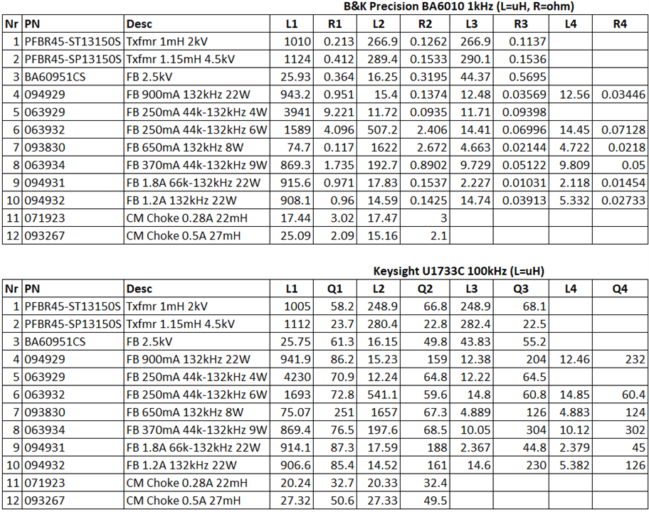
In general, the measured parameters match quite well with the datasheet specifications and measurements between equal windings only differed slightly, in part due to slight wire length and test lead positioning differences between tests. Of note is just how the inductance of the primaries are in the mH region, which is quite a lot more than I’m used to seeing on most DC-DC converter chips while the operating frequency is also a lot lower … I wonder whether this means that it won’t be possible to repurpose some of those to try driving these transformers. Nevertheless, this is a good confirmation of the data in the datasheets despite not being measured in exactly the same condition.
There are a number of other measurements that can be made of flyback transformers which I have not covered here.
Pulse and Bode Plot Comparison
Another thing I thought was worth measuring was just how these transformers behave in the frequency domain and with square wave excitation at various frequencies, compared to ordinary mains transformers.
For this, I used a Rohde and Schwarz MXO4 Oscilloscope (private review still pending) with its onboard signal generator to run some bode plots on a few products.
Bode Plots

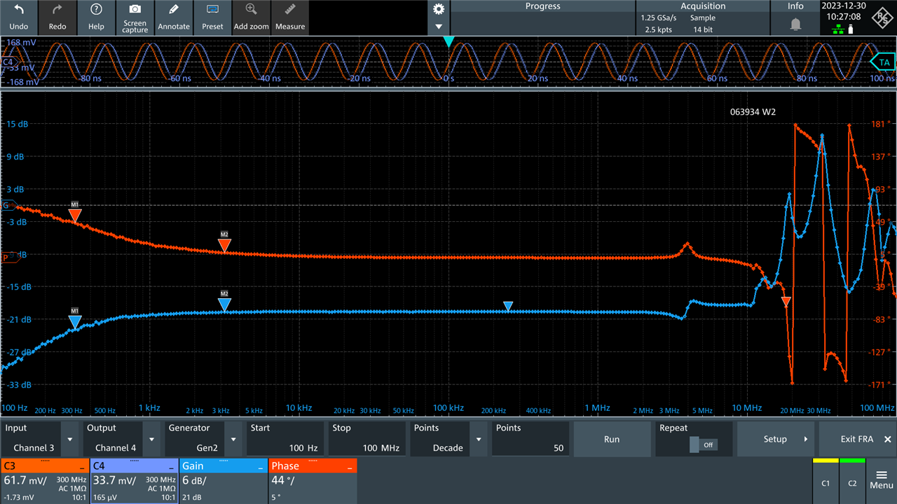
Looking at this test of a flyback transformer, it seems that the gain tails off in the low frequency end around 2kHz. I presume this is because of core saturation effects. Towards the 4MHz region, there is a bit of a dip, but self-resonance doesn’t seem to occur until 25MHz (or is that just my clip ground lead). Nevertheless, this reminds us that part of the “magic” of the small transformer is in its higher operating frequency than the mains transformer.
Testing the other winding looks similar in most ways except at higher frequencies.
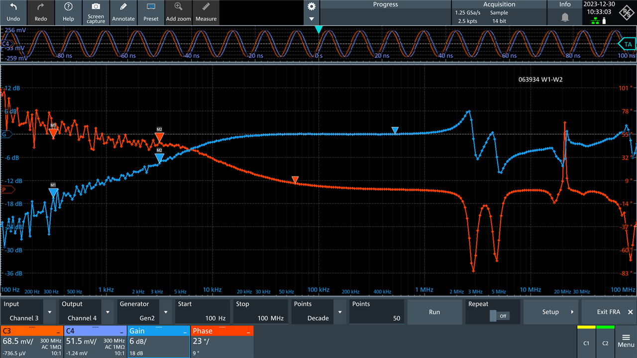
Testing between windings of equal ratios seems to suggest that maybe some kind of operation between 20kHz to 1MHz is possible, although this likely changes under load. One has to always balance things such as core losses, winding losses and switching losses when it comes to the overall converter efficiency.

This common-mode choke could sort of be used like a 1:1 transformer. Unlike the flybacks, it seems happier down to low frequencies as well, starting at 100Hz it is flat!

This is a characteristic shared by the other common-mode choke, sort of confirming in my mind that they are NOT flyback transformers.
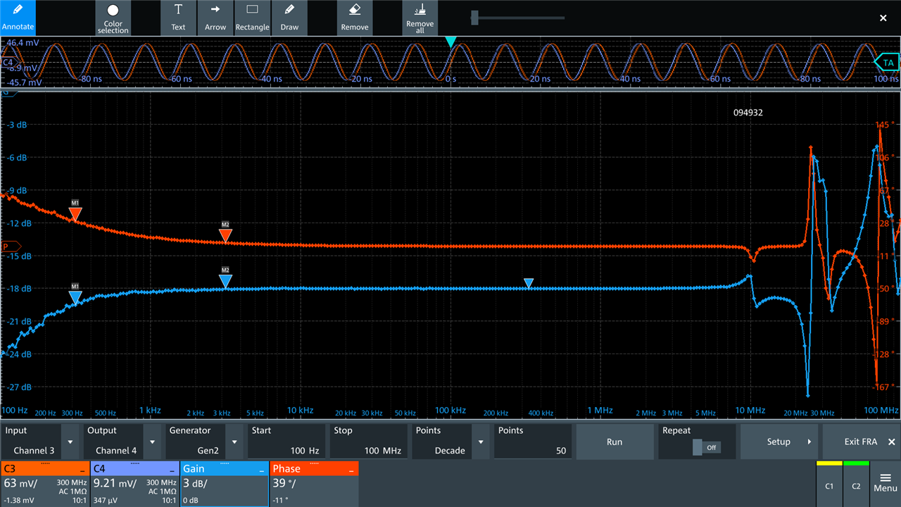
Back to a flyback now – this one seems to be quite flat across an even wider range of frequencies. This is a unit with a physically larger core, perhaps that explains it?
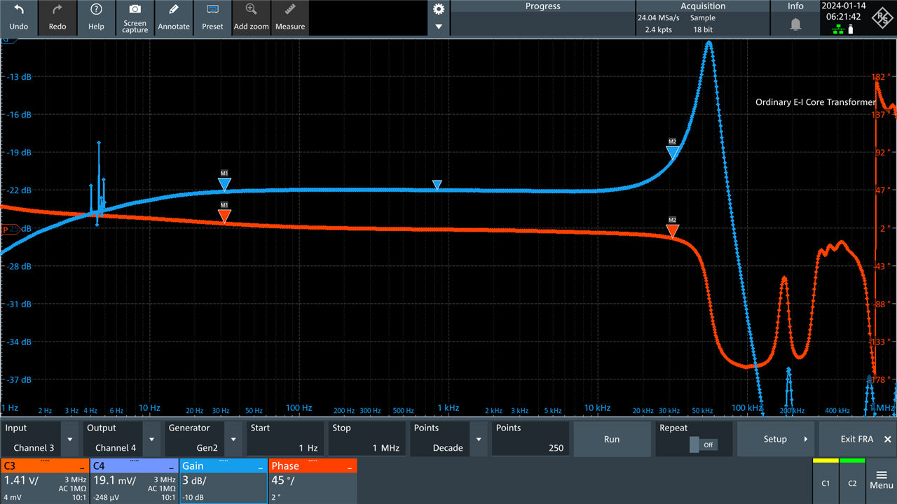
Taking the ordinary E-I core mains transformer, and ignoring the few gain spikes due to range switching, we can see that it is happier at low frequencies but starts deviating significantly by the time we pass 20kHz, being self-resonant before 100kHz.
Pulse Behaviour

When this E-I transformer is excited by a 0.5ms pulse, it sort of “rings” around 54kHz.

The same 0.5ms pulse into a flyback transformer is basically faithfully reproduced.

I pushed down to 100ns pulses, which resulted in ringing about 26MHz, but again, I wonder if this is the clip ground rather than the transformer that’s responsible for that.
Square Wave Behaviour & Ratio Measurement

I drive a 132kHz square wave from the signal generator into an 094931 flyback transformer and saw this plot. The output (purple) faithfully follows the input (orange) at a ratio of 19.71. If one computes the amplitude of input to output, it will also give us an indication of winding ratio, indicated in some of these screenshots in the teal green Math trace. The result obtained is very close to the datasheet 19.75!
However, care must be taken to choose a signal that the transformer is designed for – in this case, 132kHz square-wave seems to be the target. It is also important to note that these measurements were made under no load – it’s likely the results will vary slightly under load due to losses in the core and windings.

I pushed up to 400kHz just for fun, as some switching controllers operate at that frequency and it seems that the ratio is still pretty similar and the transformer still seemed to be working. In both cases, my input square wave turned into a bit of a “sloped-top” square wave. I feel that this is simply because the apparent impedance of the transformer at initial application of voltage is high, but as the magnetic field builds, the resistance reduces resulting in more loading on the signal generator, causing the “sloped top”.

While we can go fast, we cannot go slow. At 1kHz, the result looks like this – it seems the signal generator gives a spike and then is practically stuck at zero. I can only presume this is because we are essentially saturating the core and when transformers saturate, the apparent resistance is basically the DC winding resistance which is in the milliohms. So it seems, no matter what, we’ve got to switch somewhat fast to avoid the transformer acting like a near-short.

Putting a fast square at 132kHz into the E-I transformer for comparison resulted in an incorrect ratio and horribly corrupted waveform.

Dialling this down to 1kHz where we saw the flyback fail to operate actually shows the E-I seemingly operating with quite a bit of ringing at edge transitions but otherwise faithfully following the input.

Backing down to 50Hz, we see it seems to operate quite a bit better. It was designed for a sine wave, but a square seems to work somewhat – although the output now seems to slope downward. I suspect this is because the transformer really doesn’t hold much energy in its magnetic field (not being gapped) so as the input is practically “static” for the top or bottom of the square wave, it’s not inducing a changing flux into the secondary so it is seemingly representing the decay of stored magnetic field in the transformer collapsing (presumably).
Sorry if my terminology is all over the place – as I said in the first post, this is all completely new to me and it is something I’m still trying to reconcile in my head.
Where’s the Flyback Action?
Perhaps, based on the preamble, you were expecting to see some flyback action happening. In reality, what I’ve shown is more-or-less traditional transformer behaviour – put something in, get something (at a ratio of the input) out within a certain “range” of frequencies depending on core material, number of turns, geometry, etc. So why didn’t we see any flyback action?
Well, this is where I’d like to try drawing an analogy. Consider a flyback transformer like a swing-set which you might have played on as a kid. The flyback action is essentially what happens when your parent pushes on the swing and lets it go, storing energy as gravitational potential energy in this example. As you go forward and reach the crest, you release this stored gravitational potential energy back into kinetic energy to return essentially to where you were before, minus losses in friction with the pivots, air, etc. which represent the losses in the system.
In this set of tests, while we have “pushed the swing”, we never let go of it. The signal generator is driving the coil with some voltage/current at all times, thus it is essentially “holding onto the swing” while pushing it forward and pulling it back. Whatever flyback behaviour there is would be transferred into the signal generator which would be working its hardest to maintain the requested output. I would say the constantly-driven nature of these tests is the reason why there is no apparent flyback behaviour so far. In order for it to show, one must “let go” of the swing … drive the primary with some current, then open-circuit it to let it “fly back”. Only then might it behave as we would expect.
Conclusion
The word “flyback” can refer to several things. It can be the apparent effect of the voltage “flying back” when current is disconnected from the coil of a flyback transformer. Or it could be short for flyback topology, the circuit configuration resembling a buck-boost converter that creates an isolated buck-boost converter through the use of a flyback transformer. Or it could refer to the transformer itself, which differs from ordinary transformers with the presence of a gap to increase magnetic reluctance allowing it to store energy in the magnetic field similarly to an inductor while retaining the ability to step up or down through winding ratio and offer input to output isolation. Nevertheless, the flyback converter is a popular choice for lower power applications of approximately 100W / 10A or less, being simple to realise.
I’ve tested the flyback transformers’ parameters using a battery analyser (isolated LCR meter) and an ordinary LCR meter and found most parameters to match well despite differences in measurement conditions. Testing of the transformer behaviour under bode plotting gave us a feel of how they behave given different AC frequencies and gave a chance to measure the winding ratio. To actually see the flyback behaviour takes a little more work … so you’ll have to hang around to see if I manage to do this in a later blog.


Top Comments
-

jc2048
-
Cancel
-
Vote Up
+1
Vote Down
-
-
Sign in to reply
-
More
-
Cancel
Comment-

jc2048
-
Cancel
-
Vote Up
+1
Vote Down
-
-
Sign in to reply
-
More
-
Cancel
Children