


Now that I’ve looked at the basics of flyback topology converters and performed some basic measurements, it’s time to start some experiments. But unlike most posts, somehow I woke up this morning and chose violence against flyback transformers. This is in the name of science and safety, of course!
Insulation Resistance
The insulation on a flyback transformer is the reason why flyback converters are considered isolated. Having good insulation is vital to ensure there is no leakage of current or connection between the primary and secondary. This is especially important for the safety of the user as humans can come into contact with the output. There have been stories of USB chargers causing electrocutions – more likely than not, this is down to a failure of insulation between primary and secondary (or very poor design utilising non-isolated converters). Therefore, it is good to see that Bourns rates most of their transformers as having insulation with working voltages of 400V DC and a rated dielectric strength of 4.2kV @ 50Hz for 1-sec.
Unfortunately, I don’t have a Hi-Pot tester, but I do have the Keysight U1461A Insulation Resistance Test Multimeter which I recently replaced the OLED display on. This unit is capable of up to 1000V DC test voltages.
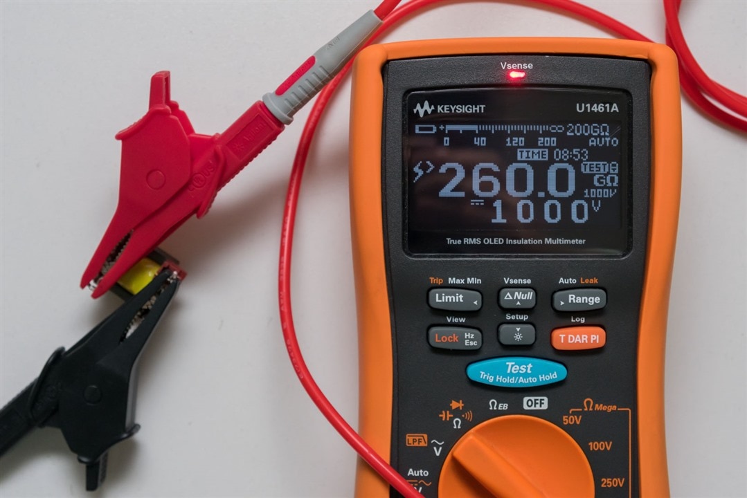
It seems unsurprising that there were no problems with this test on all my transformers. The display simply reported >260GΩ after a short time charging up the capacitance in the test leads and transformer.
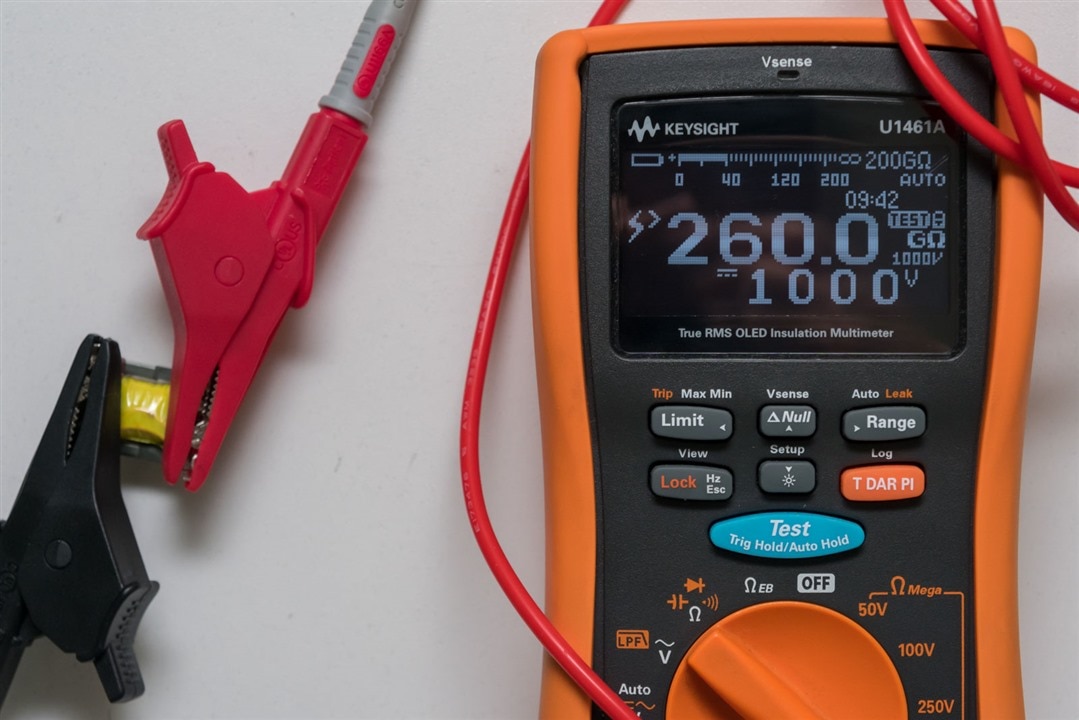
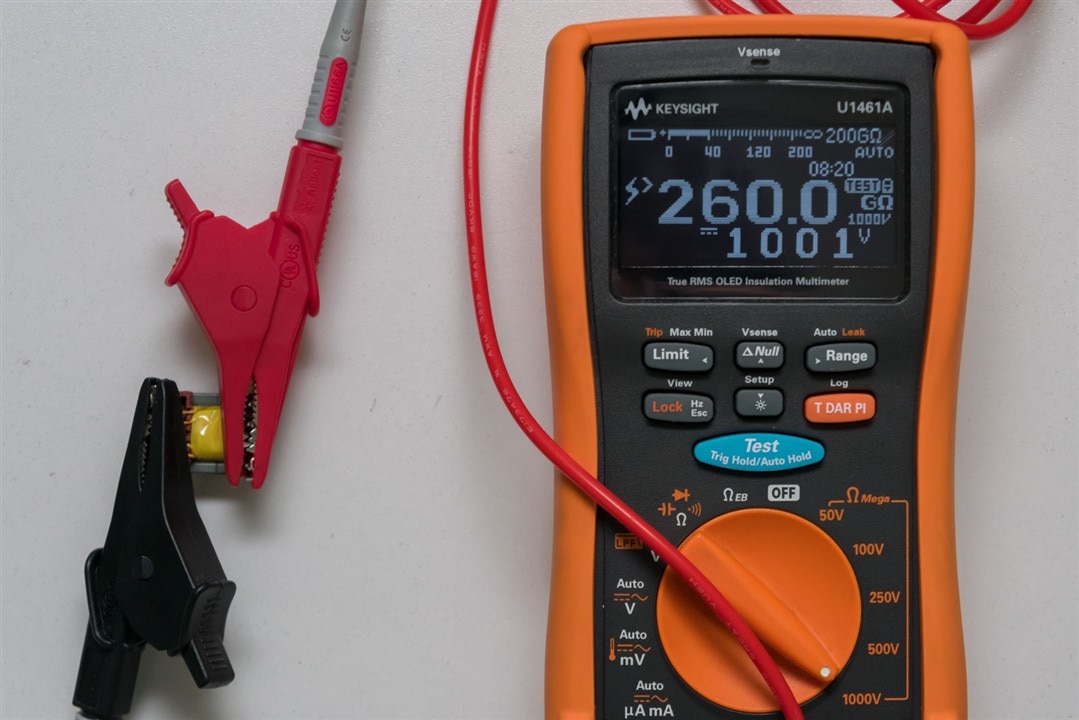
Here’s another few examples … absolutely no problems which is great news, but makes for an anticlimactic blog.
Teardown - Insulation Assessment & Where’s that Gap?!
This brings me to the question – what are the secrets of the Bourns flyback transformer? Where is this “magical” gap that I’ve heard all about and just how does the insulation work? Well, unfortunately for one flyback transformer (063929), it has been chosen as the sacrifice in the name of science.
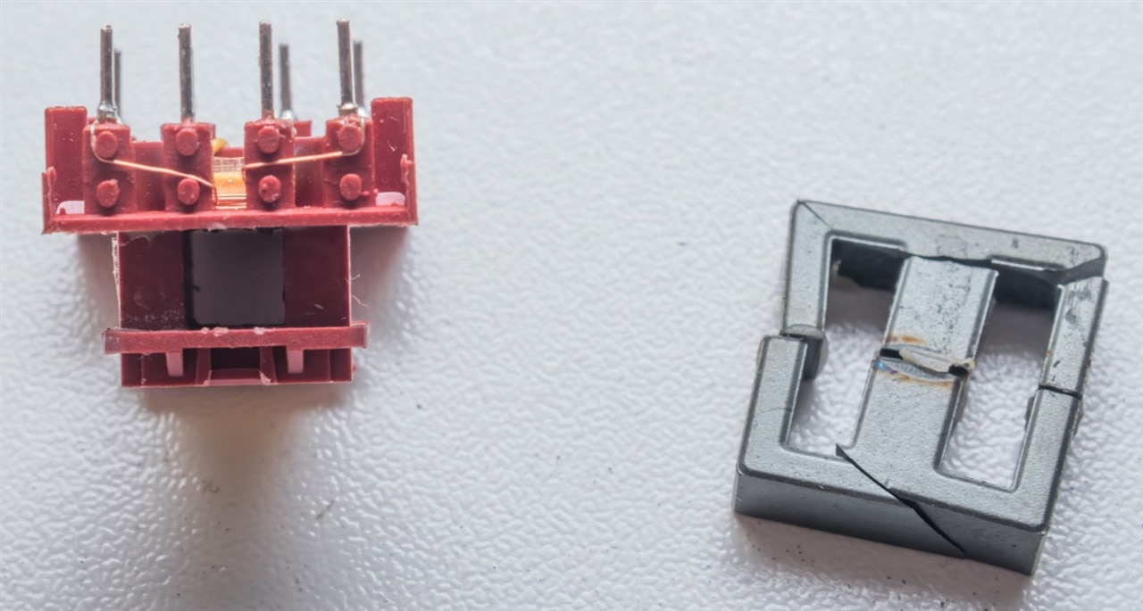
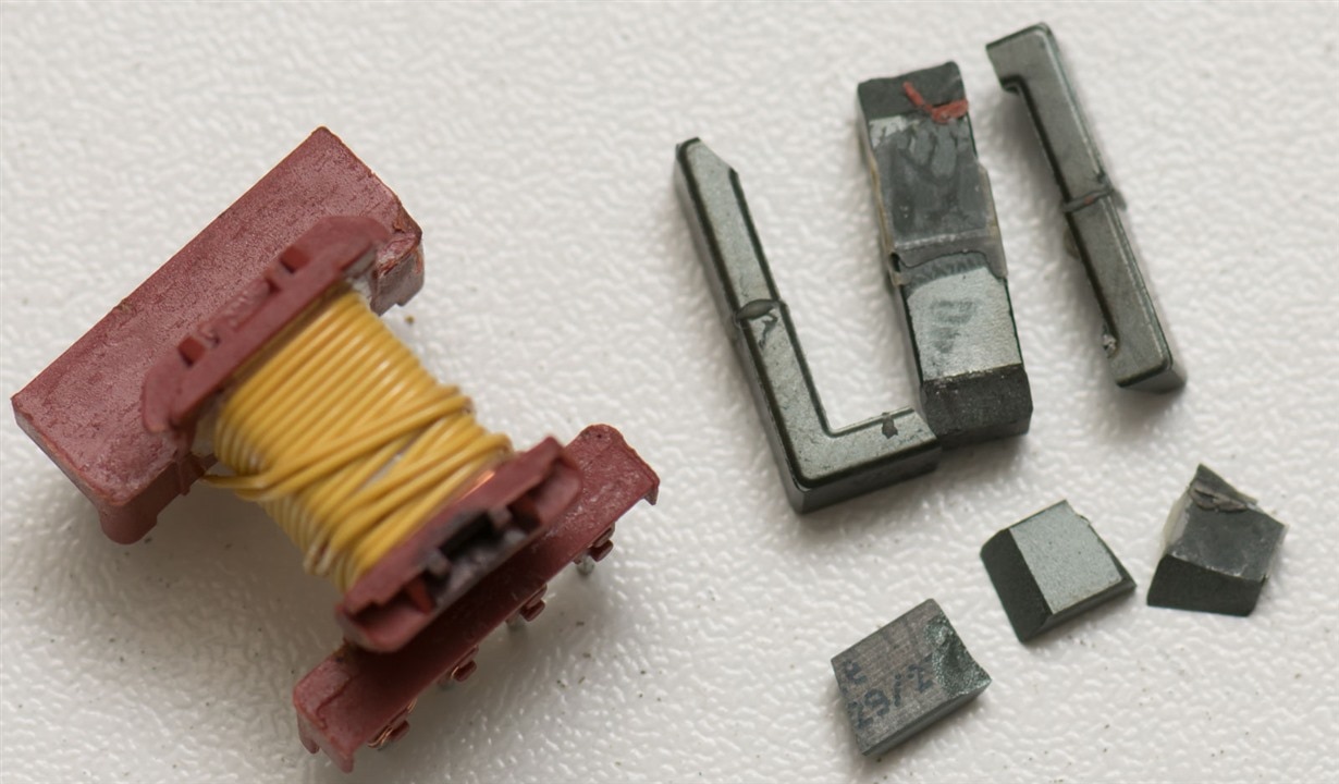
To open up the transformer, one has to first break apart the ferrite core. The core itself appears to be made of two parts, glued together. The glue is very strong, so I wasn’t able to break it neatly. Instead, a heavy tap with a screwdriver shattered the ferrite in multiple places, which continued to break under prying. The centre section of ferrite was very snugly located in the bobbin, requiring some careful hammering to remove.
There we go – the plastic bobbin with the windings and the core are now separated. A closer look at the core seems to show that the gap is in the middle where it cannot be seen. Any gaps on the outside or misalignments are probably not the intentional gap. This centre gap, at least on this side, has some discolouration which might suggest some manufacturing process which may have created some heat or chemical process which may have affected the surface of the ferrite on this side.
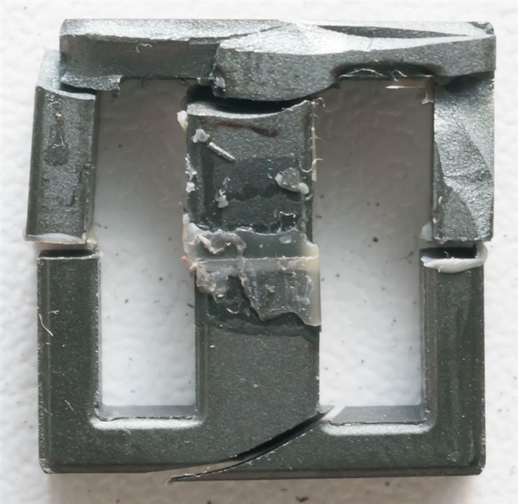
Turning it over, the discolouration does not appear to be present although there seems to be more of the glue on this side. This suggests that the cores may not be quite perfectly shaped or aligned during manufacture.
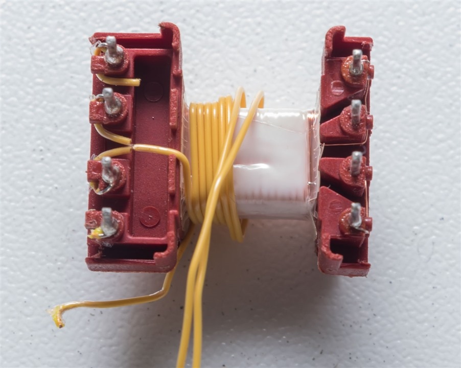
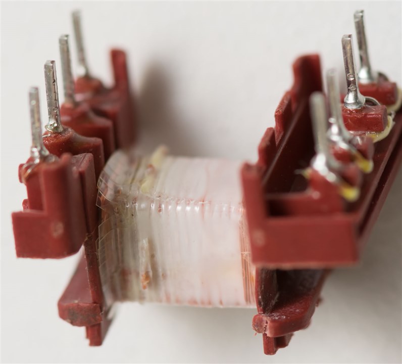
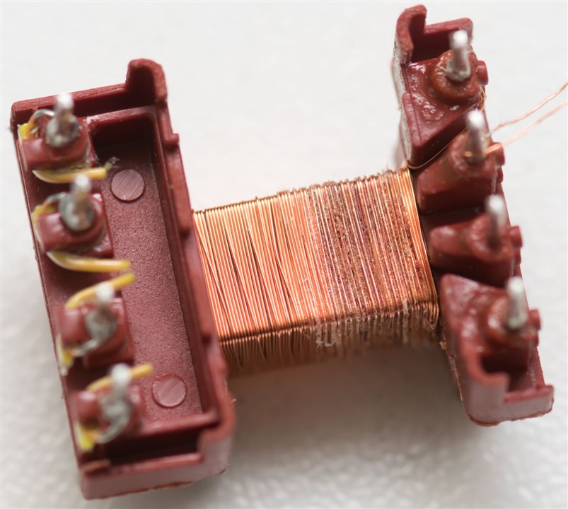
The secondaries are parallel wound in a pair using insulated wire that has yellow insulation. I’m not sure what the jacketing material is made out of.
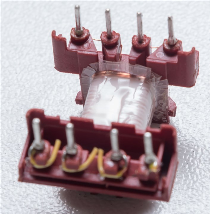
The secondary is isolated from the shield (if present) and primary by this plastic film layer. The design of this insulator is quite good, as it is wrapped around in a few layers, is longer than just the winding part of the bobbin, having slitted sections on the outside to provide additional insulation “skirt” that makes it difficult for any tracking to occur.
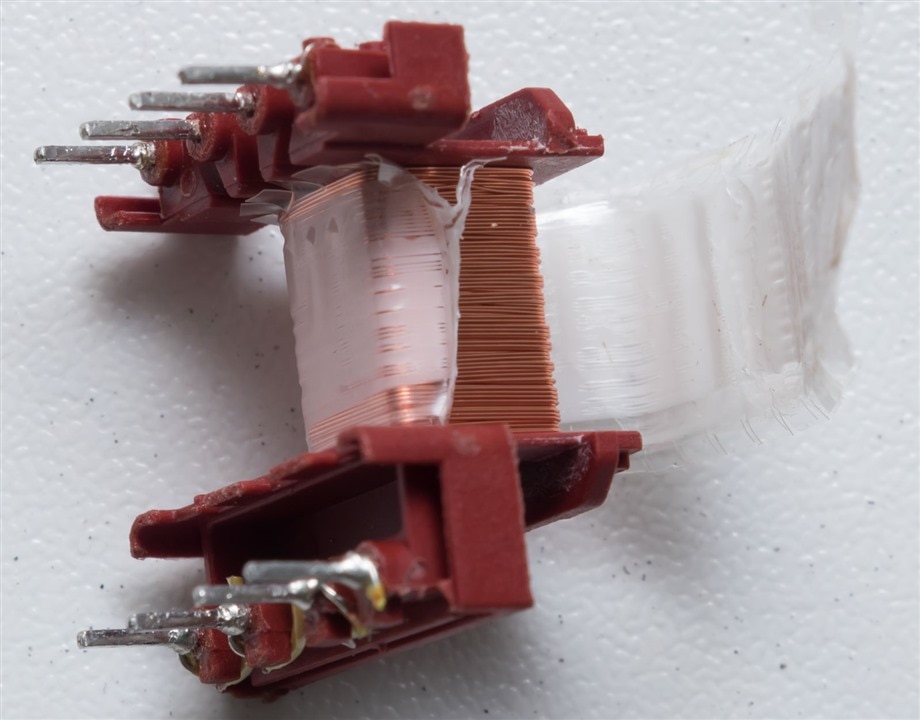
The adhesive was quite strong, so removing the insulation took some care with tweezers.
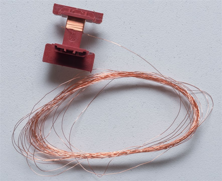
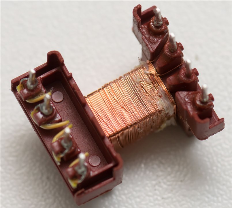
The primary is wound using thin enamelled copper wire. The primary appears to be wound in two layers and is the closest to the core.
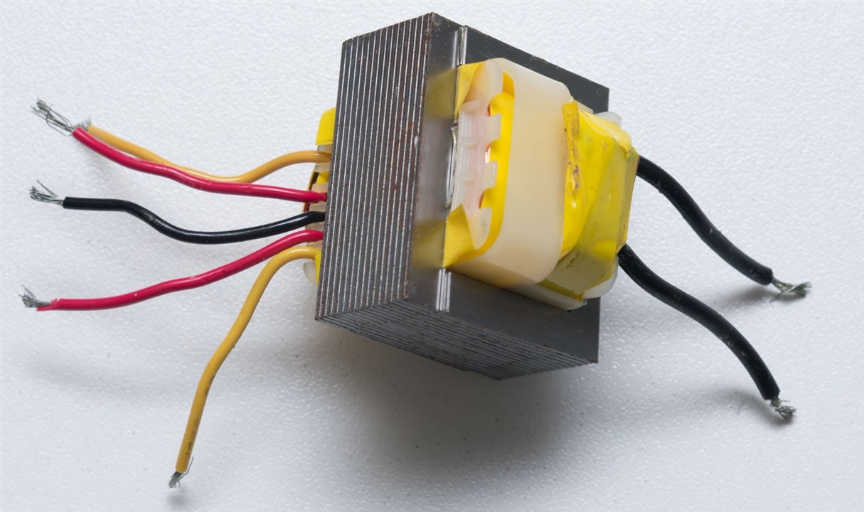
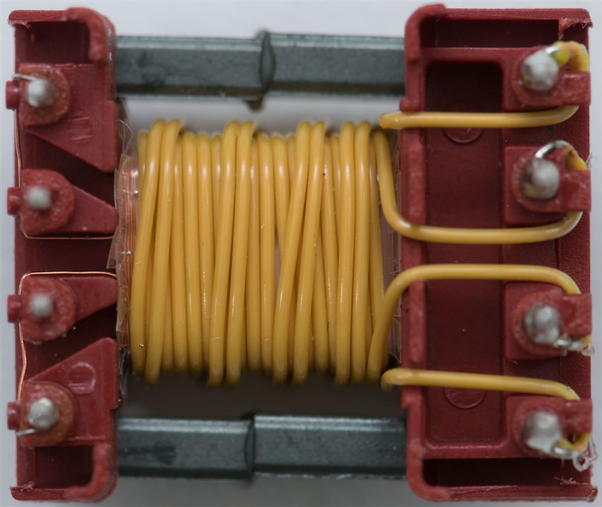
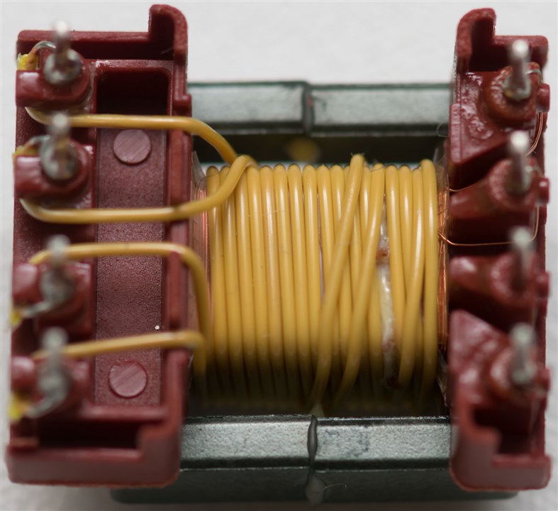
Compared to a traditional laminated core E-I transformer like the one above, the core material is definitely different. Powdered ferrite is somewhat sensitive to impact, liking to crack and be somewhat brittle. The laminated steel sheets that make up an E-I transformer are quite visible and are varnished/glued together (or in some cases, even spot welded or bolted). Because of this, it was not possible to take this one apart. Windings on this E-I transformer are in separate compartments on the plastic bobbin, insulated with yellow tape. On the flyback, the windings are one on top of the other, insulated with plastic and insulated wire, other times with tape as well. Perhaps the flyback resembles a toroid somewhat more, as those frequently are made of powdered metals and can be somewhat brittle, with windings insulated by enamel and plastic. But as they operate at different frequencies, the materials used are different and the size is different too. Functionally, the ideas of a primary and secondary winding, and of functional insulation, remain the same.
Flyback Under Abuse Condition
Given the construction and materials, I had a thought – how will the transformer react under abuse conditions? Mains transformers frequently have thermal fuses embedded in their primary windings just in case something goes wrong and the transformer ends up overheating, but I didn’t see anything like that in the flyback transformer. The primary winding in the previous transformer was also very fine, not unexpected for the low power rating, but does this mean there’s a chance that the winding itself will burn open like a fuse, or will it all heat-up and catch fire if the switching transistor blows through and the coil just ends up being shorted over a supply.
For this second experiment, another flyback transformer (063932) was sacrificed in the name of science. As I didn’t want to risk any major damage, I restricted myself to 12V/2A from a Keysight E36103A into the primary which is intended for mains 85-265V AC applications. This would limit dissipated power to 24W at the most, which would limit the chance of harm in this test. The test was observed with my Nikon D3400 DSLR and a Infiray P2 Pro Thermal Camera.
The results were interesting. When power was applied, I expected the transformer to saturate quickly and for it to act like a short over the supply, dragging its voltage down to near zero. Instead, it seemed that the transformer’s reluctance was enough to keep it at 12V/2A for quite a moment until it heated up enough to cause internal damage. During this sequence, the secondary windings started to move slightly and change colour as its insulation was exposed to the heat. Some smoke began to issue from the transformer with a few popping sounds and the temperature peaked at around 188°C. Afterward, the voltage from the supply began to drop, likely as the primary coil started to short out and the temperature began to drop. The coil did not go open circuit and the reduced power dissipation resulted in the transformer staying in the ~120°C range. After a couple of minutes, I turned off the supply, terminating the experiment and left the transformer to cool for its post-mortem.
Post-Mortem
A close look shows that the secondary windings seem to have moved a bit, exposing the plastic insulation layer between primary and secondary which appears to be somewhat affected by the heat.
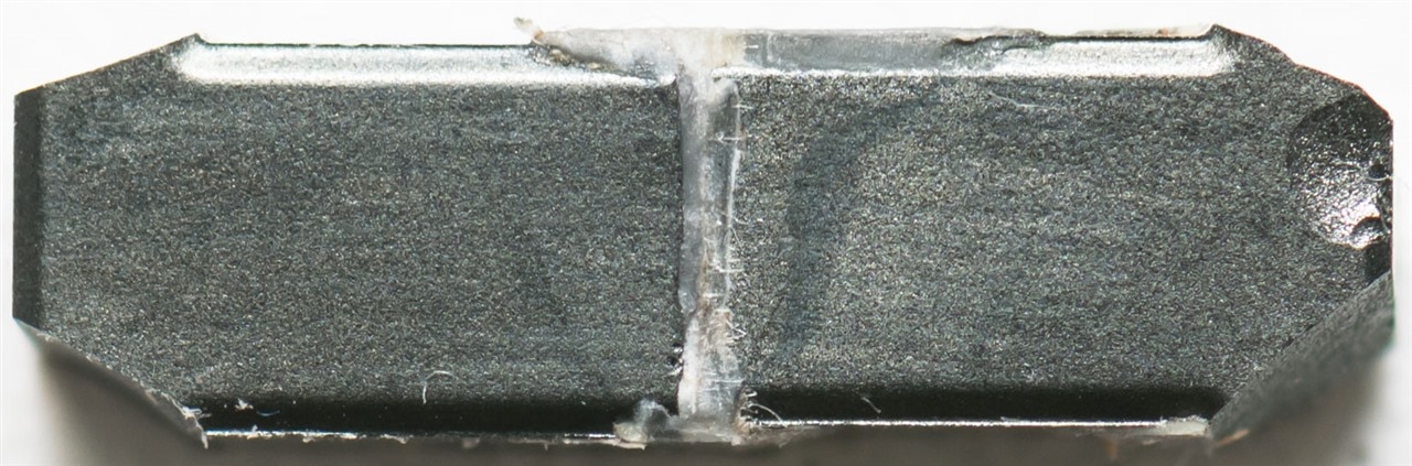
The core was broken apart to continue the teardown, with the gap in this core being more easily visible. The secondary wiring was unwound from the transformer and while the insulation may have changed colour very subtly, the insulation remained pliable and mostly undamaged.
The insulating plastic layer seems to have partly melted, becoming a little sticky and distorted. The adhesive used seems to have made removal very difficult.
Careful removal reveals the shield winding on this transformer with some discolouration of the enamelled coating especially towards the right side of the screen.
The primary winding shows the same, although somewhat darker, on its outer second wrap.
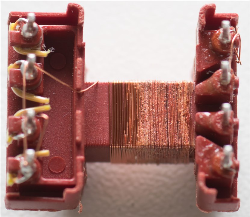
The inner wrap seems to show the enamel that has burned and then resolidified as small, rough blobs. I would assume that the winding would have shorted at this end through the two layers, thus becoming a near-short across the supply. This would be consistent with what is expected based on the peak 188°C external temperature by thermal camera as enamelled copper wire frequently is rated at 155°C operational (although can range from 105°C to 240°C). Thus, the enamel was burning off and this may have been most of the smoke observed.
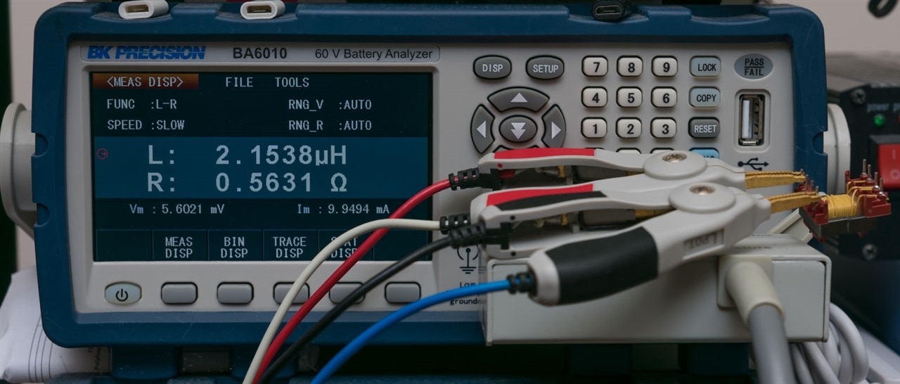
Testing on the battery analyser (LCR), it seems to measure 2.15µH on the primary coil, just a fraction of the rated 1550µH.
While this is also perhaps a bit anticlimactic, I suppose this indicates that it is important to be careful about fusing of the converter in case something bad does happen, as higher voltage/fault current may produce more dramatic failure results.
Conclusion
It would seem that insulation resistance of the transformers is not an issue, at least, to the 1000 DC level that I could test to. Teardown shows that the design involves multiple layers of insulation – secondaries can be insulated wire while primaries are often enamelled copper, with multiple-layers of oversized plastic tape to ensure good isolation. Under abuse, I found the transformer heating up to the level of insulation failure on the primary, shorting it out, but it was otherwise anticlimactic given a 12V/2A supply. Higher voltages and fault currents could result in more dramatic results, so perhaps underscoring the criticality of fusing the converter appropriately to avoid safety risks as the flyback transformer has no internal protective fuses.
While this post is perhaps very anticlimactic, at least this might be a bit of a unique contribution that puts me a little more at ease when running my own experiments which in all likelihood, may not end well.
In the next part, perhaps I shall finally get some flyback action going … whether manually or by modifying something I already have, assuming that the original transformer is somewhat close in terms of its parameters.
Top Comments