This is my first blog for the Experimenting with Gesture Sensors contest.
I'm passionate electronics engineer who loves to work on Analog circuits, wireless communication and Embedded Systems.
I recently finished my MS degree in Electrical engineering with specialization in RF and Microwave engineering. I have about 8+ years of experience in building electronic circuits. I have been selected as one of the challengers for the Experimenting with Gesture Sensors challenge sponsored by e14 and Maxim Integrated.
I received my kit around 2 weeks back and I have posted an unboxing blog here
Received the kit for experimenting with gesture sensors
Now moving on to my idea, I have planned to design a gesture-controlled FM radio for automotive infotainment systems. Now we have steering wheel mounted controls for controlling the audio, calls, and media of the car infotainment system but at times, it is distracting to use them. Also, people sitting in the back side of a car cannot control the infotainment system as nowadays we do not have remote controls like older days. Hence, a gesture based system, that can be operated by all is proposed here.
The FM radio will be built around Arduino and the popular TEA5767 FM radio module. Initially, to test the module, I will use normal tactile switches to control the radio such as change the frequency, scan the band, etc.
Later, these controls can be done using the MAX25405 gesture sensor. The out of the box demo of the MAX25405EVKIT is given later in the blog.
The MAX25405EVKIT consists of the following boards -
The MAX32620FTHR microcontroller board

The MAX25105FSHLD shield for the MAX32620FTHR board

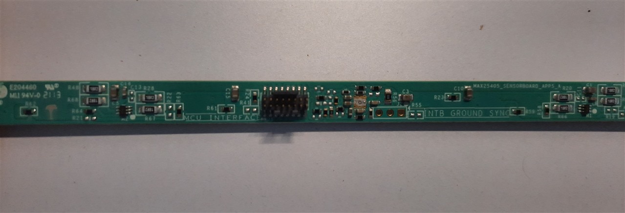
The shield has a fine pitch connector that connects to the gesture sensor PCB shown below

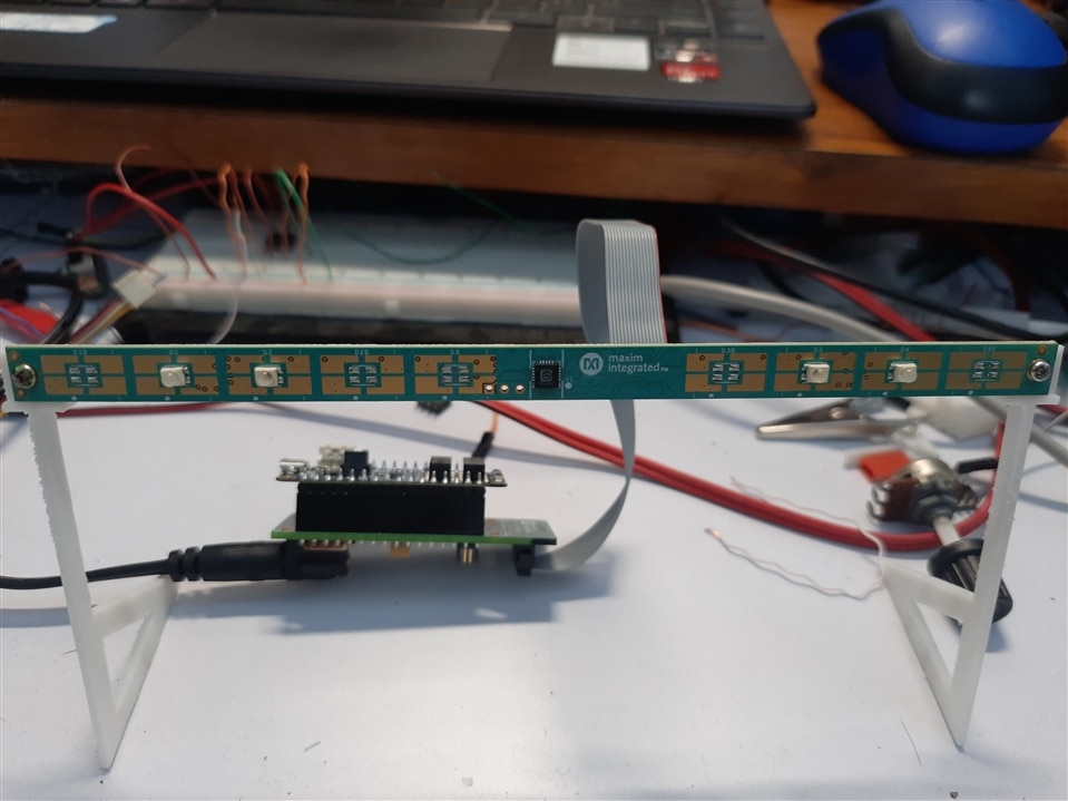
As the gesture sensor does not come with a stand, I 3D printed one from the file given on Maxim Website.
The details of the 3D printed stand are reported in another blog and can be found here 3D printed stand for gesture sensor PCB
After mounting the gesture sensor PCB onto the stand, it was time for the testing.
The MAX32620FTHR board comes pre-programmed with the firmware so that it can be tested with the Maxim GUI software for gesture recognition which is also available on the Maxim website for free. I downloaded the software and did all the connections of the boards.

As I mentioned earlier, the MAX32620FTHR board comes preloaded with the firmware. This firmware implements serial communication over USB so as to communicate with the GUI software.
Upon connecting it to the PC, in the device manager, it should show as a Maxim Serial port.

Then once you launch the GUI, you can see the interface as shown below. The board is not connected to the PC hence, the software shows SPI, COM Port offline.

One more thing to notice here is that the gesture sensor can be interfaced with the MAX32620FTHR board using I2C or SPI. By default the maxim firmware uses SPI and hence we can see SPI written in the GUI.
Now, when I connect the MAX32620FTHR with the PC, and click on reconnect COM port, it can now read the port and shows connected on COM <number> at 115200 baud rate.

Next, there are three tabs in the GUI - Heat map, gesture and proximity.

There are also certain variables on the GUI that can be changed in runtime.
First tab is of the heatmap. The heatmap shows the detection of object in the FOV of the gesture sensor.

As I move my hand around, the pixels in the heatmap change the value and it indicates that gesture is being detected. However, this may or may not be a valid gesture. The entire FOV of the sensor is divided into an arrary of pixels (60 pixels as the detector is an array of 6 x 10 pixels) for detection of the gesture. Depending upon the pixels that are highlighted, the gesture is determined.
The following gestures are supported with the MAX25405 gesture sensor kit - Rotate (CW and CCW), Swipe (UP, DOWN, LEFT, RIGHT), CLICK and analog rotation dial (if enabled).
Here's a small test video of the GUI which reads the gestures from the MAX32620FTHR board over USB connection.
Coming to my proposed idea -
The gesture controlled FM radio. Here's a block diagram of the project

There are two MCUs in this block diagram. The MAX32620FTHR understands the gestures and send the results over USB. Since there is an option in the MAX32620FTHR board to send the results over UART rather than USB, I will use UART as it is simple to interface with other MCUs (in my case Arduino).
Here, I will be using the arduino to read the gesture results from the MAX32620FTHR over UART. By default, the stock firmware in the MAX32620FTHR board has serial API implemented over USB. This can be changed in the code that is provided by Maxim. The code can be compiled using mbed-command line interface in Windows/MAC OS/Linux. I recommend using the CLI as there are certain changes that need to be made in the mbed-os files which cannot be accessed from the mbed online compiler. More on this in later blog.
Once the gesture results are read in the Arduino, depending upon the gestures various actions for the FM radio can be done such as changing the frequency, adjusting the volume, scanning for radio stations, etc.
The FM radio is based around the TEA5767 module from Philips. It seems to be an obsolete part now but such modules are still available online. It is a quite versatile IC for implementing FM radio. The IC is basically a tuner that can do all the signal processing and demodulate the FM signals and give an audio output. Note that this IC has stereo FM capability! Which is quite awesome. An external audio amplifier needs to be connected in order to hear the audio properly.
An LCD is also interfaced with the Arduino to check the frequency and display other data.
That's it for this blog. In the next blog, I will implement the serial API using UART on the MAX32620FTHR board and try reading the results in the Arduino.

-

DAB
-
Cancel
-
Vote Up
0
Vote Down
-
-
Sign in to reply
-
More
-
Cancel
Comment-

DAB
-
Cancel
-
Vote Up
0
Vote Down
-
-
Sign in to reply
-
More
-
Cancel
Children