Hello everyone. I welcome you to my third blog post as part of Experimenting with Gesture Sensors Design Challenge. In first blog I described my plans as part of competition. In my first blog I described my plans as part competition. In previous (second) blog post I shown unboxed kit and described some details about powering the kit. In this third blog post I will show evaluation software.
See it in the action!
This kit is better to see in video rather than on static video. Text later slightly duplicate video but in text I described some features which I did not recorded on video, and I will discuss all features with more details. Following video, I recorded using OpenOBS tool. Video from GUI is exactly synced with video from camera (ok, maybe there is some systematic delay, but it is not significant). You can see that sensor has very low latencies and any movement directly influences sensor data which are visible in GUI.
Modes of operation
The GUI program supports three modes of operation:
- Heat Map
- Gesture
- Proximity
Heat Map Mode
The first mode is used for visualising almost raw data from the sensor. You have seen it on video. When I had no hand in the field of view of the sensor, sensor sensed low values because amount of reflected light from IR LEDs was low. But when I add hand to the field of view, then numbers increased. Sensor has matrix of 60 IR sensors organized in 10x6 grid, for this reason we see 60 cells.
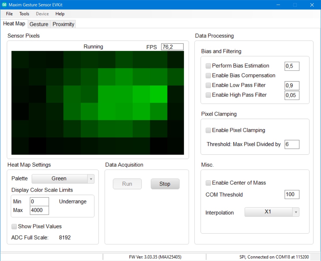
Window allows you to set some parameters. On the previous picture you have seen changed palette color to the the Green color. Default palette is Red but changing color may change your feeling. Because human eye is more sensitive to green color I had better feeling from green color but black and white also looked well and for some purposes may be good choice. This parameter of course changes nothing inside sensor.
Other very interesting parameter which I shown in video is interpolation. This feature virtually increases resolution of the sensor. It can increase resolution up to 256 times. Values of non-existing pixels are computed using linear interpolation. This feature has very interesting results and allows you to even guess shape of the object in the front of sensor when interpolation level is high enough. Multiplier 256 is nice for visualisation, but I think it is not suitable for gesture recognition because multiplying resolution increases complexity of image processing and I think that over multiplier about 16 it has no new information.
Other feature is showing pixel value. After enabling, pixel value is written on the pixel. Here you can see it:
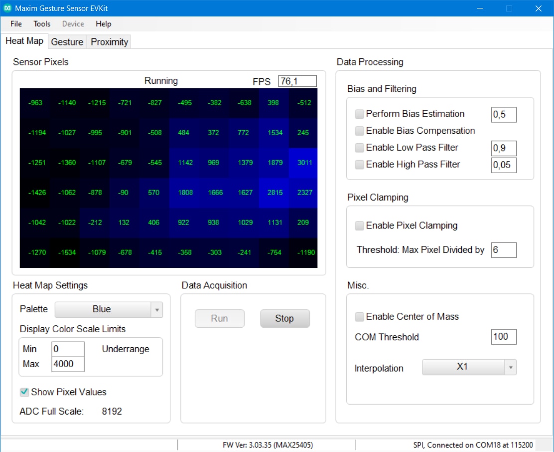
Which was interesting to me at the first look is that output contains negative values. I think it is because values are not directly from the ADCs, but they are accumulated. According to documentation MAX25405 works in way that it some fraction of time turns IR LEDs on and remaining fraction of time it turns them off (there is also some other delays but they are not very important for now). Depending on selected mode sensor counts up values from ADC when IR LEDs are ON and count down when LEDs are OFF. It is designed in this way for ambient light compensation. It works in a way that when sampling with IR LEDs ON then accumulated value is sum of reflected light from IR (this is what we want) + other external and ambient light (this we do not want). In time when IR LEDs are OFF we receive only value caused by external light. For this reason, we subtract them. Because time periods when LED is ON and OFF are similar, sensor subtract similar amount of light that was added in ON phase by ambient light to the measurement. At the end we should receive only amount of light which was sourced by IR LEDs and reflected by target subject. But subtraction of course mean that we can kindly receive negative values.
Other parameters directly corresponding to the pixel values are scale limits. In case when full scale would be used for computing heat map, then most of the time all values will be very dark. For this reason, you can limit minimum and maximum offsets for color calculation. For example, on the picture above you can see that maximum is 4000 which mzeans that value of 4000 will be fully bright blue and possible values above 4000 will cause rescaling and colors start varying in time. Similarly, it applies for lower bound limit. You can see that window on picture above indicate underrange which is caused by negative values and program had to adjust color space to distinguish from values below 0 even it normally shows them dark.
On the right you can see Pixel clamping feature which sets negative values to 0 and divides pixel values somehow, but currently I do not understand purpose of this division.
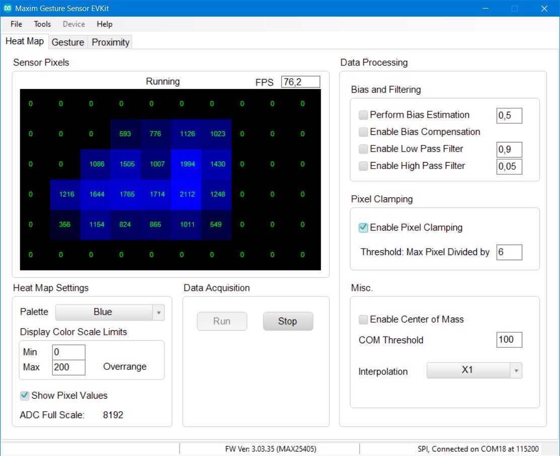
The last configurable parameters correspond to bias and filtering. These values do not correspond to neighbouring pixels but rather in changes in time. Low/high pass filter are interesting. Low pass filter high frequencies but also slow down growth (for example when you place hand in the front of sensor) and fall of values (for example when you take your hand back). High pass in the other hand highlights movements. For example, when you drag hand to the front of the sensor and let it in the front to of sensor, you will see values increase right after dragging hand to do field of view and then colorful pixel will slightly disappear even you still hold your hand in the front of sensor.
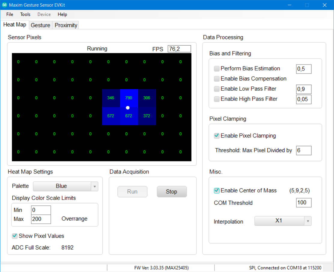
The last checkbox “Enable Center of Mass” allows you to see output from computation of center of the area detected by sensor. It is not fixed to centers of pixels. Rather it is computed by some interpolation. I can imagine that it is used for example for detecting finger location surrounded by hand.
Gesture Detection Mode
The second tab is the most interesting one because it shows output from gesture detection algorithm.
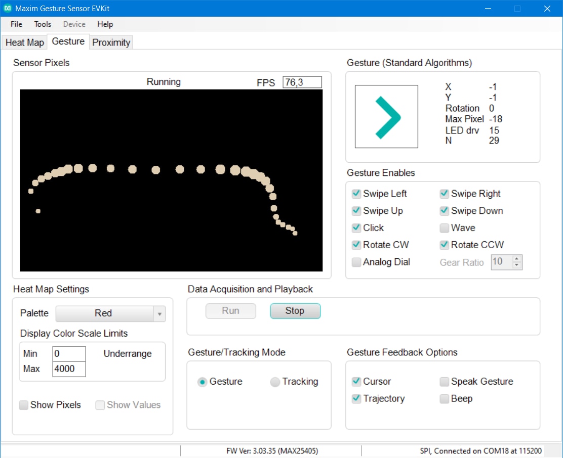
As you can see that gesture detection is most probably based on center of mass detection which was also visible on previous tab. You can also notice that dots representing movement near sensor are bigger than the dots at the end when I was removing hand out of sensor range.
Some configuration parameters are the same as they were on Heat Map tab. The first different parameters are enabled gestures. If you do not need to detect some gesture, you can disable it. Some of them are also disabled by default but you can enable them. Very cool to me are analog dial and rotate CCW gesture. They are quite accurate. They are much more accurate than I originally expected from only 60 pixels.

The gesture feedback sets what will program do when it detects gesture. It can for example speak gesture name or beep. Finally, you can set gesture or tracking mode. To me it looks that tracking mode just disables gesture detection and shows only trace of dots, but SDK provided by Maxim contains different algorithm for this mode, so most probably there are more complex difference.
Proximity Mode
Last mode is proximity mode. This mode is useful when you just need to detect where is object present (right top corner, bottom right, and so on). Segments are flashing when user move hand and progress bar occurs when he/she stop moving hand. When it holds hand at the same position progress bar grow and after some time segment get “selected”. I can imagine use case for this mode when navigating user in some menu and selecting options.
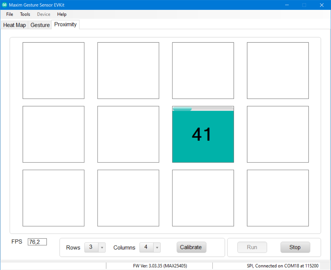
This mode offers very few configuration settings. You can for example set number of columns and rows. There is some calibration button, but I did not know its purpose. It does nothing at the first look. Maybe it is used for redefining borders of cells. In case of using EVKIT on desk it does not matter but when installed (for example in car) you may face “issue” that due to orientation and limited positioning options you will detect all useful data in for example left 60% of area. Other region will be normally inaccessible or in this because it would be useful to redefine borders of cell to match this reduced field of view. But I was unable to set this. Maybe this button is used for something different.
Frame per Second (FPS)
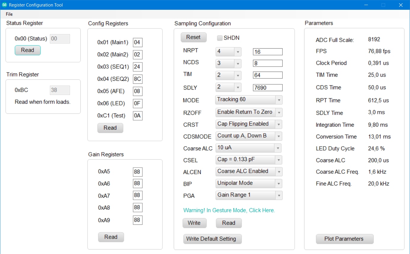
My last note is about speed. As you can see sampling rate was in all modes about 76.2 FPS. This is nice, I think. Sampling rate do not depend on data or presence of object. This is difference with for example ToF sensors. Many of them has advanced logic which results to non-deterministic performance dependent on scene (and ambient light level, target object reflectance, …). Some ToFs for example time-outs when no object is present and this behaviour reducing FPS in that situation.
Performance of MAX25405 depends only on configuration. MAX25405 has multiple registers relating to sequencing. You can set duration of time when LED is ON, where it is OFF, duration between sampling and some other options. According to the EVKIT documentation GUI software use one good-known settings. If you want, then you can change register values manually and FPS can change according to your setting. Window also contains computed other some parameters resulting from register values. Some parameters are interesting to me because I did not find any references to them in MAX25405 datasheet (chip datasheet, not the EVKIT datasheet).
Closing
Thank you for reading this blog as part of Experimenting with Gesture Sensor Design Challenge. In this blog post I described software side of evaluation kit and exposed some details and thoughts about MAX25405 sensor which I gained after first hours of experimenting with sensor (and few other hours spend by reading documentation). Next blog will be shorter. I want to describe my stand which I later build for the sensor. In this blog I used EVKIT placed just on the desk but because it is so light, I decided to build robust stand for it. Because I do not have 3D printer, I did not make plastic stand from CAD files provided by Maxim, but I built stand differently. I will not spoil more details currently, so stay tuned to my next blog post.
Next blog: Blog #4: Building stand for MAX25405 EVKIT


Top Comments
-

DukeKaboom
-
Cancel
-
Vote Up
0
Vote Down
-
-
Sign in to reply
-
More
-
Cancel
Comment-

DukeKaboom
-
Cancel
-
Vote Up
0
Vote Down
-
-
Sign in to reply
-
More
-
Cancel
Children