


Hello everyone. I welcome you to my fifth blog as part of Experimenting with Gesture Sensors Design Challenge. In previous blog I described my plans as part of this design challenge (blog #1), shown unboxing of the MAX25405 Gesture Sensor Evaluation Kit (blog #2), shown software provided for evaluating the gesture sensor (blog #3) and shown stand which I build for easier evaluation (blog #4). Today I continue my journey of experimenting with Maxim Integrated MAX25405 Gesture Sensor, and I will show Serial (UART) API which is provided by firmware preprogramed in microcontroller which is bundled with the Kit. The API is easiest way to run gesture detection using evaluation kit and I will use it in (at least) one of my projects which I promised in first blog.
Virtual UART
The UART interface is fully virtual. By default, no TX and RX signals are routed using any PCB trace on any board. Instead, it is implemented using USB CDC (Communication Device Class) interface. There is no onboard converter. USB CDC is implemented in firmware which runs of MAX32620 MCU. USB signals are connected directly to this microcontroller. Firmware generates and consumes all data from virtual UART line. Device is identified to the host computer as Maxim Serial Port and uses Maxim’s Vendor ID 0x0B6A and Device Id 0x4360. Device Id is most probably assigned to only firmware related to MAX25405. I tested all other Maxims devices which I have and all of them have different device IDs so most probably you can reliably use it for distinguishing devices.
Documentation
Most knowledge which I will show later I found in public application note 7422. This application note contains basic description of commands which you can execute using UART API. I will try to provide more details and some my thoughts about UART API to extend knowledge which you can gain from the application note mentioned above.
Commands
Maxim do not follow any standard like AT commands but instead they use pure commands with text replies. But commands are still very easy to generate, and replies are easy to parse. All commands are encoded using ASCII characters and most replies also do. But when enabled streaming mode, then data are encoded in binary as you will see later. Commands has parameters specified after command name, and all parameters are delimited using space. In case of numeric arguments there is very flexible syntax of encoding numbers. You can write them directly in decimal like 123 but you can also write them in hexadecimal format with 0x prefix. For example, commands “reg read 0x03 1” and “reg read 3 1” and “reg read 3 0x01” are all equivalent. Hexadecimal format is useful for specifying register address (some registers are located at very high address, so hexadecimal format is useful here) and for example for specifying lengths natural decimal notation is more useful.
Opening port
In my case COM port related to device was COM18. For a first time I tried it to open in putty but it did not work well. I tried to type and send (by enter) commands, but it did nothing. Because there are no physical UART lines there is no place to check that keystrokes were transmitted correctly. After some investigations I found that issue is caused by putty. It sends newlines using LF character, but device requires CR and LF. After searching I found that CR can be send using Ctrl – J, so every time I want to send command, I pressed Ctrl + J (this send CR) and then enter (this send LF). This worked but the similar issue appeared on terminal output. Newlines were partially “broken” but output was readable. Note that firmware do not implement echo feature so you do not see what you have typed but you see only outputs. On following screenshot, you can see outputs from ver command (first time I used only enter without Ctrl + J so I received invalid command reply. Second time I did it correctly). ver command prints firmware version.

Switching to Linux
After few experiments I found easier to switch to Linux and us minicom for getting functional new lines. In fact, there are better forks of putty which allows you to configure this, but I decided to go minicom way rather. So, I connected USB cable to Raspberry Pi and connected over SSH to it. Then I connected to serial port using minicom. Enter start working naturally and newlines in output also do.
ver

Checking device connectivity
After checking that firmware correctly prints version and communication works, I started by checking connectivity with MAX25405. For doing so I used command for reading registers. According to datasheet there are multiple regions are of configuration registers. Main configuration registers are at address 1 and there 6 registers in total. Register at address 0 is status register. So, for a first time I read 6 + 1 registers from address 0. In case of disconnected device, it print all FF.
reg read 0 7

As you can see first register is zero which indicates that no interrupt happened, and other configuration registers contains non-zero values. If you read my third blog, then you maybe noticed that you have already seen these values. The same values were shown in Register Configuration Tool:

For sure I also read other registers at addresses 0xA5 and 0xC1.
reg read 0xA5 5
reg read 0xC1 1

Note that GUI tools mention trim register at address 0xBC but this register is not documented anywhere in datasheet. Later after writing last blog I found that most probably this is not the only secret register because I for example never read about any capacitance in datasheet and there is some CSEL option with pF options. Window on screenshot above looks like good source of secret options of MAX25405 which would be nice to experiment with!
Reading gesture data
The most important command is poll command which prints coma separated values including some floats. All fields are well documented in application note mentioned at the beginning of this blog post.
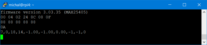
In the command output the most important is first field which indicates type of detected gesture. On the screenshot above it is number 7 which indicates that last detected gesture is swipe down which corresponds to number 7. All possible values are mentioned in app note as follows:

After you read gesture then next reading start reporting 0 until firmware detect next gesture.

But as you can see some fields are updated like number of pixels and maxim values (3rd and 4th parameters) even no gesture is detected (first parameter is 0). Later you can see additional gesture (gesture number 4 – swipe left) detected.
For detecting gestures, you should call this command regularly. Maxim recommends matching frequency of sending this command to FPS calculated based on configuration registers or at least 10 times per seconds. I of course did not satisfy this requirement when sending commands manually but nice is that some field (for example detected gesture) persists set even longer time and you do not miss them.
Reading RAW data
Because we have access to registers, we can access RAW data from ADC accumulators. These data are input for gesture detecting algorithm running on MAX32620 MCU (the same MCU which handles UART communication). For reading values of all 60 pixels we need to read 120 registers because every pixel value is 16-bit (2 bytes) wide. 120 pixel registers starts at address 16 (0x10). Command for reading all pixel data is:
reg read 0x10 120
And output can look as follows.

Experienced hexadecimal readers can notice one interesting thing: 16-bit numbers are encoded using big-endian encoding and not the little-endian which is more natural to almost every nowadays processor.
Proximity mode
All what you have seen as far was executed when firmware was in standard gesture detecting mode. But you can change it to tracking/proximity mode. Both modes are enabled using track command. In case of proximity mode you specify number of segments. I show both modes in my previous blog post. Now you will see how they work at UART interface level.
After changing to proximity mode sensor stop reporting any gestures but only gesture available to you is gesture number 10 (LINGER_ON_REGION). This ”gesture” happens when user let hand on some region for longer period of time. Using second and third to last parameters you can see coordinates of selected segment.
track 3 2
poll

As I stated in previous blog, I consider this mode nice for menus. Note that you can of course switch modes on the fly. For example, you can generally use gesture mode and when you change screen on display to some menu, then switch mode of firmware to proximity mode.
Streaming data
Until now all outputs were replies to commands which I executed. But you can enable streaming mode and then device will stream information about gestures as well as raw data from pixels as soon as they are available. Then you do not ned to manually execute poll command. Note that streamed data are binary, so after enabling by “stream on” command you most probably will not be able to identify them by hand. Also note that application note from Maxim do not specify this mode, hence format of binary data is not documented but can be deduced from Firmware Framework available from Maxim.
stream on

Last words
And this is all. There are some other commands (for example writing registry and help command) but they are like commands which I described here. This was last blog from theory subsection. In next blog post I will show my first experiments which required programming. I will show my first experiment with connecting to EVKIT from JavaScript which is not very common language for communicating with hardware devices! I want to use this technology later in one gesture-controlled game which I promised in my first blog. So, stay tuned. I think it will be big fun. I also get some ideas on experiments which I originally do not planned. I want to try run sensor in some obscure configurations for experimenting and see results. For my idea I will need to process data faster and differently, so I plan to implement my own low-level library for configuring and gathering data from sensor but not for processing data (detecting gestures). But this is currently long-term plan. Currently I am busy with games as promised in first blog. Thank you for your attention and if you have any question or feedback, kindly write it in the comments below.
Next blog: Blog #6: Connecting to MAX25405EVKIT using Web Browser and TypeScript


