Hello everyone. I welcome you to my next blog as part of Experimenting with Gesture Sensor Design Challenge. In my previous blog I described debugging of interesting issue with firmware compiled form sources provided by Maxim and today I will describe another issue. Sadly, this issue could not be solved using openocd and gdb. For summary this is 8th blog as part of my serie. In 1st blog I described my plans as part of competition, in 2nd blog I shown unboxed evaluation kit, in 3rd blog I described evaluation PC program provided by Maxim for evaluation MAX25405 Gesture Sensor, in 4th blog I shown my stand which I build for better experience with the sensor, in 5th blog I accessed evaluation kit using provided virtual UART interface, in 6th blog post I shown possibility to communicate with evaluation kit from web browser and finally, in already mentioned 7th blog I described debugging procedure which I used for helping another challenger on the forum.
Powering the Kit (again)
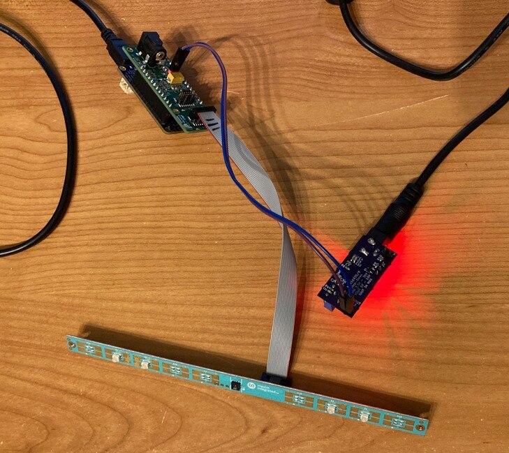
Maybe you remember my second blog post, in this blog I described my alternate way of powering the kit because provided adapter has only US plug and because I am based in Europe, I need different power adapter. Because I have no 3.3V adapter at home I decided to do alternate solution. I researched in evaluation kit schematics and found that it is possible to provide power using pin headers. So, I utilized my DC/DC Step Down converter with MAX16935 chip and powered the kit through it. I connected 12V source to the regulator and regulated 3.3V I connected to my MAX25405 Gesture Sensor evaluation kit. Connection (the same picture was in blog #2) looked as follows and it worked well:
2 Barrel Jack Connectors and Accident
As you may notice there are two barrel jacks connectors now:
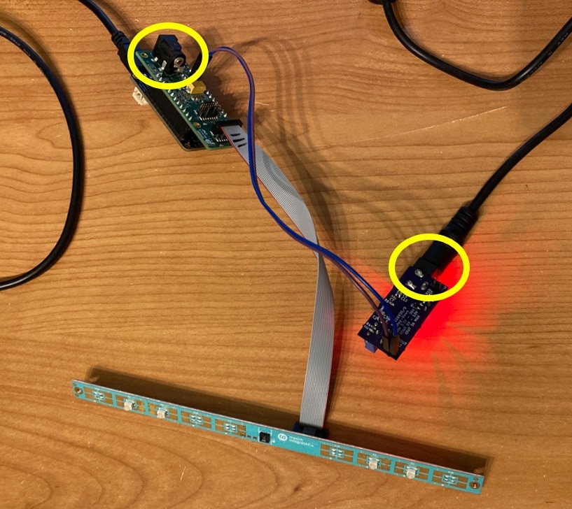
And one day I did huge mistake. When I was connecting 12V power supply I did not insert it to the barrel jack of voltage regulator but instead I connected it directly to the barrel jack of EVKIT shield which means that I connected 12V to 3.3V power supply net of the evaluation kit and 12V burned my MAX25405 chip. I noticed this mistake aprox. 10 seconds after I connected it. I immediately disconnected it. I noticed something is wrong right after I connected power supply because I have heard click from the connector (later I realized that it was most probably some flash inside the connector).
Extent of damages
After I realized my mistake and disconnected 12V power supply from 3.3V branch I started thinking what happened. I realized that most probably I did not burned MAX25405 only but also burned other parts of the kit (IR LEDs), also FTHR bord with MCU was exposed to this voltage and at last my voltage regulator was back powered. But as far I did not analyse it properly.
As a next step I tried carefully connecting barrel jack to my power regulator (MAX16935) without EVKIT connected. I checked that it works. It was backpowered by 12V but his Absolute Maximum Ratings was not violated. It is designed for output in rage 1 – 10V but Absolute Maximum Ratings allow bringing up to 12V on the output pin. So, LEDs on this board was litting slightly more than they should but power regulator survived.
Shield was the first thing in the way. It has only one active part: MAX8891 LDO for converting 3.3V (12V) to 1.8V. Absolute Maximum Ratings allows up to 7V on input. I violated this rule, but it survived. After connecting proper voltage (3.3) I measured 1.818V on its output. There are some passives. I can’t check them because I have no BOM (even schematics is not publicly available for the shield board). Generally, Sensor board has all capacitors rated for 16V and more. I guess that Shield is designed similarly.
The most interesting part is MAX32620 microcontroller and FTHR board. After connecting it to the computer it enumerated over USB. This was big surprise. At first it is good to mention that I do not know how much it was exposed to 12V. 12V was directly attached to VDDIOH power supply but this MCU has more power supplies and I guess CPU, RTC and VDDIO was not exposed to the 12V directly (but maybe indirectly). At the end MCU partially works. It enumerates over USB. I can flash them. SWD interface works. SPI and UART GPIOs works. The only issue I noticed is non-functional reset button (reset-pin). Reset button does not reset MCU anymore. It is interesting because reset pin was not directly exposed to 12V but to the 1.8V which are on the same branch which power CPU and CPU survived in comparison with reset pin structure. It is interesting but it is not significant issue for me. When I want to reset MCU now I have to power cycle it. The other part on FTHR board is PMIC. It looks that it works, but I did not tested battery charging.
As far all boards survived but what about the most important board with MAX25405 sensor? It does not. My MAX25405 do not work anymore. I checked transactions using logic analyzer and noticed following findings:
- After power up it should trigger power-on-reset interrupt, but it does not
- MISO line is held low for all time
- Register writes are ignored
- Register reads always returns 0x00 because MISO is held low
- Signal for driving LEDs is held low for all time
It looks it is completely dead.
The sensor is not the only part on board. There are also 4 IR LEDs and transistors for switching them. Transistor looks that they survived. Absolute Ratings allows voltage between Drain and Source as high as 20V which was not violated. But on the Gate, it allows only up to +8V which was violated. It is hard to estimate if current limit (0.8A) was or was not violated. If the driving pin was held low (like it is stuck now) then it was violated. If it behaved differently at theme of burning, then it maybe was not violated. Later I checked that transistor survived. The last parts are IR LEDs. They are designed for high continuous currents of 100 mA. Increasing the voltage increased the current also. Absolute maxim ratings of LEDs allow 1A current peak and 100 mA continuously. Because sensor enables LED for only short period of time Maxim designed it with resistor allowing current about 275 mA. Increasing voltage from 3.3 to 12V cause increasing of forward voltage and according to my calculation LEDs were exposed to 1.5A currents (this most probably caused flashes in connector when I was connecting it). Also note it was not pulse current but rather it was continuous current. Current depends on the same which I mentioned with transistor above. If the transistor was closed, then everything was ok. But it if it was open, then it was significantly violated and LED exposed to significant currents. I guess it was open and I guess that 1.5A current flowing through the 4 LEDs (about 6A in total). I guess these 6 Amps were cause for flash inside connector when I was connecting it.
To summary Shield survived, MCU mostly survived, Gesture Sensor is dead and transistor and LEDs are at this moment currently hard to check because transistor drive pin is held low by dead gesture sensor.
Also notice that when burning sensor and possibly LEDs, they did not smell. No PCB trace burn. And there are no any visible defect on any chips or boards.
Game Over of New Kit?
After I realized my sensor is dead, I was thinking what next. My first idea was just leaving the competition. Because I was impressed by sensor performance and capabilities, I decided to order new kit and continue my journey.
So, for now I have new Kit and can continue as part of competition. New Kit come from different distributor than Element14 ordered kits for this contest and also it has different date code and batch number. It came in bigger box. Kit was differently assembled but content is exactly the same including missing USB cable. Most probably all kits are missing USB cables even it is mentioned on Maxim website.
Rework of Burned Kit
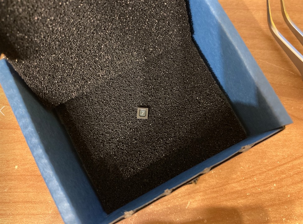
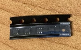
Later after I ordered new kit I still had burned kit on the desk and was thinking about it. At the same time I was choosing parts for order as part of my Project14 World in Motion competition reward. And I got another idea. I will order new MAX25405 Chip, IR LEDs and footprint compatible transistors (because I was not sure if LEDs and transistors are or are not burned) as part of this reward and then rework my burned kit. Last week I received first part of my reward (I will post blog describing other parts of my reward later. Now I am busy with competition.) and it included new sensor chip, LEDs (only one of two kinds for some reason) and transistors. Here is new hero of this competition:
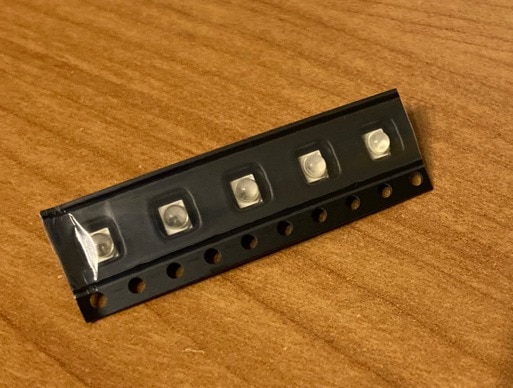
Here are new LEDs:
And finally, transistors:
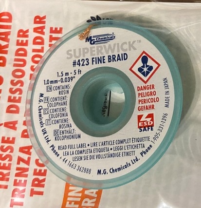
The other pard of my Project14 basked which I utilized as part of rework (for a first time) is superwick. It is much better than my previous Chinese wick.
Desoldering Burned Sensor
The first step was desoldering old burned MAX25405 Gesture Sensor. I used hot air. After desoldering it looked as follows.
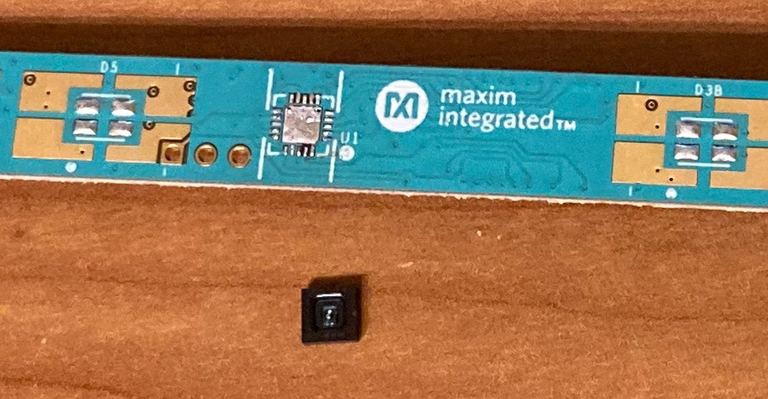
Then I used superwick for removing as much old solder as possible.
Then I soldered new chip. I don’t like soldering QFN packages. In fact, I hate it. At first, I placed solder paste to exposed pad. Then I used hotair. Because I feel that I placed so much paste, I decided to use superwick for removing some and adjusting its amount. Then I used hand solder for connecting pins to pad. It always took me hours to solder QFN chips. At the end I was mostly satisfied. I am not sure, but maybe I have soldering bridge between GND and SEL pin. Even after multiple attempts I was unable to ensure they are not shorted. There is slight gap between them, but I was unable to “extend” it. SEL is used for selecting I2C or SPI. Because it is possibly grounded it means that selected interface is SPI which is fine because evaluation software uses exclusively SPI and Shield and FTHR board has data bus connected to SPI only. SPI is also preferred because of higher bandwidth for bitmap values transfers. So even these pins are shorted it is not significant issue.
Result
And after completing soldering I tested non-continuity between VCC and GND and checked some ESD diodes for testing that pins are correctly connected. Note that is hard to test all pins. It is hard to even find components because in main area there are no silkscreen labels because there is no space left on the narrow board. So, I tested it only basically. I assembled the kit, powered it, measured voltages, then connected MAX32620FTHR to PC using USB cable and opened evaluation kit GUI program. Pressed run button to start collecting data from sensor and It worked! I fixed my broken kit! At this moment I also realized that transistor and IR LEDs are functional. So, I did not need to rework them.
Experimenting with Two Gesture Sensors
Now I have two MAX25405 Gesture Sensor evaluation kits (and one burned chip). One kit is the replacement kit which I ordered and second is my original kit which I reworked. So, the question is now what will I do with two kits?

Answer is simple. I can evaluate it’s dual operation capabilities! MAX25405 support running in configuration of two sensor. It has configurable synchronization mechanism with SYNC pin. Synchronization is needed for preventing crosstalk of IR LEDs driven by both sensor at the same time. When configured, one sensor act as master and it drives SYNC pin and the other sensor (configured as slave) use this pin as input and prevent operating when signal on this pin is active. Because now I have two sensors, I can test this mode. In the other hand dual sensor gesture detection is quite a complicated thing. I did not find any reference for dual-sensor operation in EVKIT PC GUI program and also never find any reference in documentation to firmware with UART API. All these expect only single sensor. So, using both sensor for gesture detection requires lot of work, but possibly allows detecting more advanced gestures and more accurate detection. Depending on free time I will try it implement or at least create some tool for visualizing (and comparing) values from both sensors at the same time.
Experimenting with IR LEDs configurations
As I mentioned in the article, I also ordered IR LEDs because I was not sure that they burnt, or they did not burn. They did not burn (or least it looks that they are fully functional. Maybe they changed some properties when overloading, but from practical point of view they work good for gesture detection). So now it may look that I have useless 5 IR LEDs, but I will utilize them. As I stated in one of my previous blog post, EVKIT has 9 footprints for IR LED and there are soldered only 4 of them. Odd number of LEDs because there are one LED (referred as D5 in schematics and on board) which is driven differently. Note that it is not placed by default. Remaining 8 LEDS (4 of them are placed) are driven using external N-Channel MOSFETs. They are driven by PWM signal. PWM signal properties (like duty cycle) depend on sequencing configuration of MAX25405 and power is regulated only by onboard fixed-value resistors. In opposition LED D5 is directly connected to MAX25405 and it drives it from constant-current source. This source is configurable, and user can select currents from 0 to 200 mA in steps of 13.3 mA.
LED D5 is not placed by default, but because I have IR LEDs I will try to solder it and check how do results change when selecting this alternate way of driving LED.
Prevention
Right after I received my replacement kit (before I did rework) I taken several mitigations on prevent doing the same mistake again. Originally, I used glue tape to block insertion jack to the shield.
I was also analysing other risks and I decided to solder dual-color pinhead on the new Kit for indicating polarity of powering pinhead (red is VCC and blue is ground).
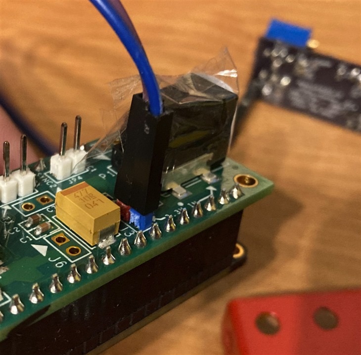
All parts exposed to stress above Absolute Maximum Ratings I marked with red sticker. Note that this blog is out of order. Accident happened in second week of competition, but I was waiting for parts for rework. You may notice this red sticker on some photos in already published blogs.

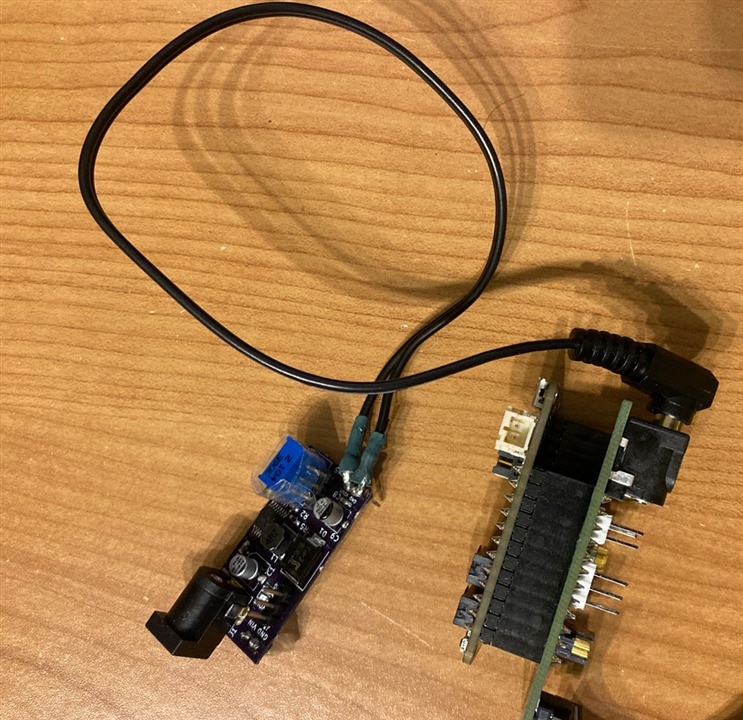
Later I decided to do another upgrade of my power module for prevent similar accidents. I soldered barrel jack plug to the output, so now I do not use pinheads while letting one barrel jack empty, but rather I connect barrel jack plug to the shield and because I do not disconnect power module I always have only one socket available (thus it is not possible select bad one).
Summary
And this is all for this blog. In this blog I described sad accident, but at the end it was happy end and I also get opportunity for. While this accident almost kicked me out of competition I decided to continue and later I also succeeded with rework.
Next blog: Blog #9: Gesture Controlled Tetris

