


This is Blog 2 of 2 for the Experimenting with Inductors elemet14 Challenge. In this blog, I design a circuit that will accept a multitude of DC voltages for its power source. If you haven't seen it yet, check out the first blog,Experimenting with Inductors - Sean Miller Blog 1 of 2: The Crazy Inductor Learn-o-Nator, to learn about inductors and what has led up to this project.
TABLE OF CONTENTS
|
Experimenting with KEMET Inductors |
|---|
INTRODUCTION
In this blog, we'll build a couple of power supply circuits to use in future PCB designs for my datalogging needs and experiment with the affect of different rated KEMET inductors has on the circuits. One thing all my datalogger projects have in common is they all need some form of DC power, but the voltage and connectors available at their point of use all could be different. For instance, in the field, I might be able to find 24V from the Distributed Control System (DCS). Also, we have a lot of small 12V SLA batteries I could use. For low power projects, a 9V will do nicely. The sensors and microcontrollers typically need 5V or 3.3V. So, in this blog, we'll design some design blocks that we can use for future projects to step down any voltage from 24V and lower to 5V and 3.3V.
In the first blog, we did a deep dive on what an inductor does using a model I called the Crazy Inductor Learn-o-Nator. So, how does all that theory apply to my project?

Crazy Inductor Learn-o-Nator1 Used to Understand Inductors
For a switching regulator circuit, the inductor works with a capacitor to manage and smooth the energy involved with the switching action. Remember that the inductor will store up energy in a magnectic field around the coil. When current slows or stops, that field will serve as electron inertia and the inductor will continue to throw electrons past it similar to our massive paddle wheel in the Learn-o-Nator above. With a capacitor paired with the inductor, they can create a very stable constant voltage and good current source. In the Experiments section, we'll see what happens when you remove that capacitor.
Let's take a look at the circuit design next.
CIRCUIT DESIGN
When researching for this blog, I stumbled upon a great toolkit available from Texas Instruments to support designing with their Integrated Circuits. It's called the Webench2. One design tool it has is for switching regulator circuits. You simply put in your specs and it gives you the schematic, Eagle File, and a BOM!

TI's Webench Free Online Design Tool - just put in your specs and out comes the design and BOM

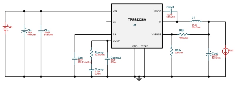
Output of the TI Webench Design Tool for Switching Regulators: 8V - 24V Input, 3A, 5V Output DC Power Supply Circuit
Output of the TI Webench Design Tool for Switching Regulators: 8 V - 24V Input, 3A, 3.3V Output DC Power Supply Circuit
Per the datasheet3, the output voltage is set with a resistor divider from the output node to the VSENSE pin. TI recommends using resistors with 1% tolerance or better. You may begin with a value of 10 kΩ for the upper resistor divider, Rfbt, and use Equation 1 to calculate the value of Rfbb. To improve efficiency for loads less than an amp, use larger value resistors. But, if the values are too high, then the regulator is more susceptible to noise and voltage errors from the VSENSE input current are noticeable.

Equation 1: Setting the Output Voltage
The output of the TI Webench tool also includes an Eagle schematic and a BOM. I was glad to see, it even sourced KEMET components by default. With this design and my existing stash of through-hole components, we can prototype and experiment. So, I placed an order for some TPS54336A Switching Regulators2.
BILL OF MATERIALS
So, what does such a circuit cost? Hold your seat - a whopping $2.50 (US). Well, a little more for the hobbyist since we aren't buying in bulk. With shipping costs, I was able to get all the BOM for about $6 per power supply circuit. I bought enough to supply future builds to make the shipping fee worth it.
5V BOM
| Part | Manufacturer | Part Number | Quantity | Description |
| Css | TDK | CGA1A2X7R1A103K030BACGA1A2X7R1A103K030BA | 1 | Cap: 10 nF Total Derated Cap: 10 nF VDC: 10 V ESR: 280.21 mΩ Package: 0201_033 |
| Rfbt | Vishay-Dale | CRCW0402100KFKEDCRCW0402100KFKED | 1 | Resistance: 100 kΩ Tolerance: 1.0% Power: 63 mW |
| U1 | Texas Instruments | TPS54336ADDARTPS54336ADDAR | 1 | |
| Cinx | Kemet | C0603C104K5RACTUC0603C104K5RACTU | 1 | Cap: 100 nF Total Derated Cap: 100 nF VDC: 50 V ESR: 139 mΩ Package: 0603 |
| L1 | Kemet | MPX1D0530L100MPX1D0530L100 | 1 | L: 10 µH IDC: 3.1 A |
| Rfbb | Vishay-Dale | CRCW040219K1FKEDCRCW040219K1FKED | 1 | Resistance: 19.1 kΩ Tolerance: 1.0% Power: 63 mW |
| Cboot | Kemet | C0805C104M5RACTUC0805C104M5RACTU | 1 | Cap: 100 nF Total Derated Cap: 100 nF VDC: 50 V ESR: 64 mΩ Package: 0805 |
| Ccomp | Kemet | C0603C561J5GACTUC0603C561J5GACTU | 1 | Cap: 560 pF Total Derated Cap: 560 pF VDC: 50 V ESR: 1 mΩ Package: 0603 |
| Rcomp | Yageo | CRCW040223K7FKEDCRCW040223K7FKED | 1 | Resistance: 23.7 kΩ Tolerance: 1.0% Power: 50 mW |
| Cout | Panasonic | 16SVPG270M16SVPG270M | 1 | Cap: 270 µF Total Derated Cap: 270 µF VDC: 16 V ESR: 8 mΩ Package: 6.3x9.9 |
| Ccomp2 | Kemet | C0603C430J5GACTUC0603C430J5GACTU | 1 | Cap: 43 pF Total Derated Cap: 43 pF VDC: 50 V ESR: 0 Ω Package: 0603 |
| Cin | Kemet | T495X156K050ATE300T495X156K050ATE300 | 3 | Cap: 15 µF Total Derated Cap: 45 µF VDC: 50 V ESR: 300 mΩ Package: X |
3.3V BOM
| Part | Manufacturer | Part Number | Quantity | Description |
| Css | Kemet | C0603C103K5RACTUC0603C103K5RACTU | 1 | Cap: 10 nF Total Derated Cap: 10 nF VDC: 50 V ESR: 1 mΩ Package: 0603 |
| Rfbt | Vishay-Dale | CRCW0402100KFKEDCRCW0402100KFKED | 1 | Resistance: 100 kΩ Tolerance: 1.0% Power: 63 mW |
| U1 | Texas Instruments | TPS54336ADDARTPS54336ADDAR | 1 | |
| Cinx | Kemet | C0805C104M5RACTUC0805C104M5RACTU | 1 | Cap: 100 nF Total Derated Cap: 100 nF VDC: 50 V ESR: 64 mΩ Package: 0805 |
| L1 | Kemet | MPX1D0530L100MPX1D0530L100 | 1 | L: 10 µH IDC: 3.1 A |
| Rfbb | Vishay-Dale | TNPW060332K0BEEATNPW060332K0BEEA | 1 | Resistance: 32 kΩ Tolerance: 0.1% Power: 63 mW (note this has a large minimum order quantity, so you'd probably want to substitute) |
| Cboot | Kemet | C0805C104M5RACTUC0805C104M5RACTU | 1 | Cap: 100 nF Total Derated Cap: 100 nF VDC: 50 V ESR: 64 mΩ Package: 0805 |
| Ccomp | Kemet | C0402C112J5GAC7867C0402C112J5GAC7867 | 1 | Cap: 1.1 nF Total Derated Cap: 1.1 nF VDC: 50 V ESR: 0 Ω Package: 0402 |
| Rcomp | Yageo | CRCW040212K1FKEDCRCW040212K1FKED | 1 | Resistance: 12.1 kΩ Tolerance: 1.0% Power: 50 mW |
| Cout | Kemet | T520D227M010ATE018T520D227M010ATE018 | 2 | Cap: 220 µF Total Derated Cap: 440 µF VDC: 10 V ESR: 18 mΩ Package: D |
| Ccomp2 | Kemet | C0805C101K5GACTUC0805C101K5GACTU | 1 | Cap: 100 pF Total Derated Cap: 100 pF VDC: 50 V ESR: 74 mΩ Package: 0805 |
| Cin | Kemet | T495X106K050ATE300T495X106K050ATE300 | 2 | Cap: 10 µF Total Derated Cap: 20 µF VDC: 50 V ESR: 300 mΩ Package: X |
PROTOTYPING
Before sending a PCB design off to get fabricated, it's always good to prototype it first to ensure it will work. This will require a breadboard which uses through hole components. My BOM from Webench can be replicated with through hole components I had on hand, but the main switching regulator, the TPS54336ADDATPS54336ADDA step down converter has a surface mount package. So, I first need to make a little custom breakout board to convert its package for use with a breadboard. I use the Ferric Chloride etching approach as shown below:
|
1. Laser Print the Etchant Mask for the Circuit on Transparency Paper |
2. Wire Brush off the Oxide Layer |
|
3. Stick It Down with Aluminum Tape (like you find on ductwork) |
4. Iron on Max Temp for 30 seconds |
|
5. Fill in Any Discontinuities with a Circuit Marker. Use a razor knife to remove any shorts. |
6. Drop it into Ferric Chloride for 1 Hour (warm it and swirl for faster results) |
|
7. Wire Brush off the mask and use a blade to remove any shorts |
8. Drill and Solder (hot air or a small point iron) |


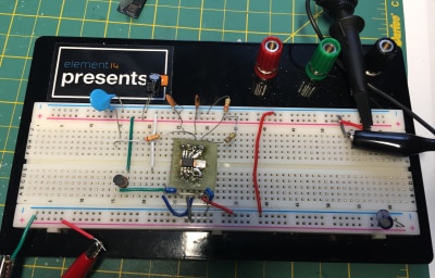
Digging through my parts bin, we had ourselves a prototype:

Our Breadboarded Power Supply Prototype
EXPERIMENTS
To experiment, I hooked up the oscilloscope so I could study the signal. For the prototype, I didn't have the exact resistors on hand, so my Voltage was ~4.5V instead of 5V. However, it did prove steady regardless of the power supply voltage setting. For fun, I poke, pushed, and pulled out components to see their effect. Here are some pictures of interest:


Green is Input, Yellow is Output
Appears the Anomaly is seen at the Power Supply to my Regulator, too


To see all the action in real time, here is the video:
The blip I was seeing was even seen at the power supply side. However, when I took my regulator out and probed just the power supply, I did not see the blip. However, it did have significant ripple. The jumper wires, where they were connected on the board, and even me just touching the resistor would change the amplitude of the ripple by 10's of mV. So, I suspect the "blip" is a reaction to switching of the regulator and it would be much less significant on a PCB where there isn't additional resistance and inductance involved with jumper wires and extra copper as on a bread board.
CIRCUIT EFFICIENCY
The efficiency of the circuit is provided with the Webench tool. As you can see below, the higher the input voltage, the more loss you have to achieve 5V. Also, as more load is pulled by the auxillary devices, it becomes less efficient. For my dataloggers, I'll be in the 90% range with no more than 1A load. This chart does show how I'm best to run my 12V batteries in parallel versus series (24V) to get maximum battery life. Let's see how our designs compare to a linear (non-switching) regulator:

Our 5V Switching Regulator Design Efficiency Curves

Old School 7805 Linear 5V Regulator (non-switching) Compared to Switching Regulator4
The Lowest Curve is the 7805
As you can see above, a non-switching, linear regulator never achieves the efficiency of our switching regulator design. In addition, most 7805 regulators are rated for less than 2 amps and give off a lot of heat. This requires a bulky heat sink. So, definitely, the switching regulator circuit using some additional tiny capacitors, resistors, and KEMET inductor is a much preferred approach.
PROJECT SUMMARY
This two blog project for the Experimenting with Inductors Challenge was very fun. Going into the contest, I had not studied inductors in over 25 years. That course of study was just algebra and schematics with no direct applications. In Blog 1, with the virtual model of the Crazy Inductor Learn-o-Nator, I gained a solid understanding of inductance and how it can be considered electron inertia. In this blog, I got to see how one can smooth the voltage output of a switching regulator through capacitors, resistors, and inductors. I also got to see how small KEMET5 can make their inductors - even their thru-hole packages - so that power circuits can be as small as possible. I hope the two circuits will serve you well in your designs and you gained a few good references along the way as did I.
REFERENCES
- Blog #1:Experimenting with Inductors - Sean Miller Blog 1 of 2: The Crazy Inductor Learn-o-Nator
- Texas Instrument's Webench: https://webench.ti.com/power-designer/switching-regulator
- TPS54336A Switching Regulator Datasheet: http://www.ti.com/lit/ds/symlink/tps54336a.pdf
- Dimension Engineering Switching Regulator Data Sheet Efficiency Curves: https://www.robotgear.com.au/Cache/Files/Files/146_DE-SW0XX.pdf
- KEMET Website: https://ec.kemet.com/blog/why-it-matters-magnetic-material-types/
Top Comments