Table of Contents
This is a second blog in 5 part blog
Overhead tank monitoring for smart home/industry : BLOG 1
Understanding the official kit and components
Before diving deep into the project it is important to understand the kit and how it can be utilised for my project. Schneider electric website provides all the details necessary get started with these devices. Each device page contains documents such as data sheet, user manual and instruction sheet. Data sheets are useful to get more technical details of these devices while user manuals provide insight about how these devices functions. Here is an example of Harmony ZBRN2 web page.
SCHNEIDER ELECTRIC ABLM1A24025 POWER SUPPLY
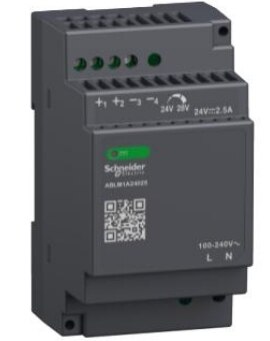
The power supply with DC 24V is required to power the PLC and other devices available in the kit. It is rated as 60W power. It accepts 100-240VAC as input and has 24V 2.5Amps output. There are two output connections meaning two devices can be connected easily and more can be added by multiplying the connections. Only condition is that we do not increase the rated power requirements.
To conclude in short about this power supply from Schneider electric it can be used to power PLC, Harmony Hub ZBRN2, HMI display and other components such as relay. So perfectly suitable for my application and given other components in the kit.
MODICON PLC M251 TM251MESE
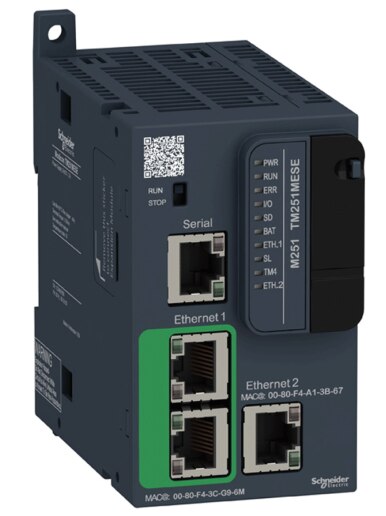
Modicon M251 is a Schneider electric PLC series with following key features
- 64 Mbytes RAM, of which 8 Mbytes available for the application
- 24VDC power supply
- 128 Mbytes of flash memory
- 1 serial line port
- 1 USB mini-B programming port
- 1 dual port Ethernet switch
- 1 Ethernet port for fieldbus
- SD card slot
- Expansion module
The M251 Logic controller is programmed with EcoStructure Machine Expert Software that supports coding in following IEC-61131-3 programming languages
- IL: Instruction list
- ST: Structured text
- FBD: Function block diagram
- SFC: Sequential function chart
- LD: Ladder diagram
HARMONY HUB ZBRN2 & HARMONY ZBRRH
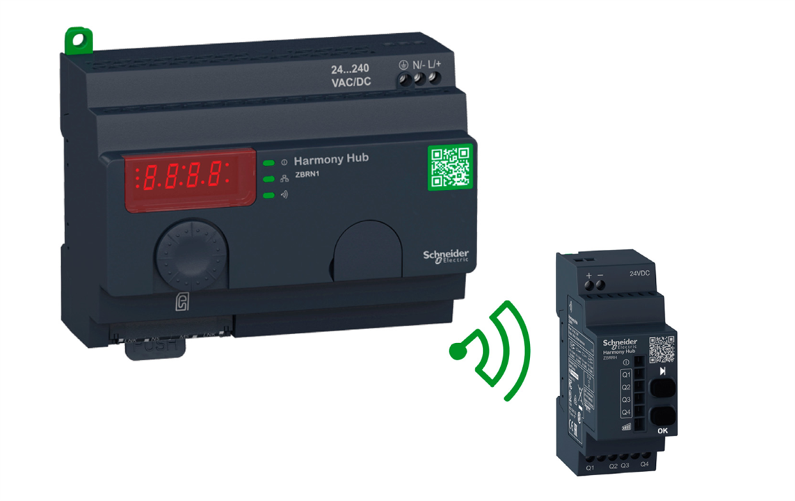
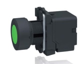

Modicon ZBRN2 Harmony Hub is a wireless receiver hub for communication with ZBRT1/2 types of push button switches and ZBRRH receiver. It can communicate with upto 60 ZBRRH receivers. It has the following key features.
- Four 7-segment display with 5 LEDs
- POWER, RADIO SIGNAL STRENGH and COMMUNICATION LEDs
- Connector for optional external antenna
- 2 RJ-45 Modbus serial line connectors
- Jog dial
- SD-card slot
- 24.....240 VDC/VAC power support
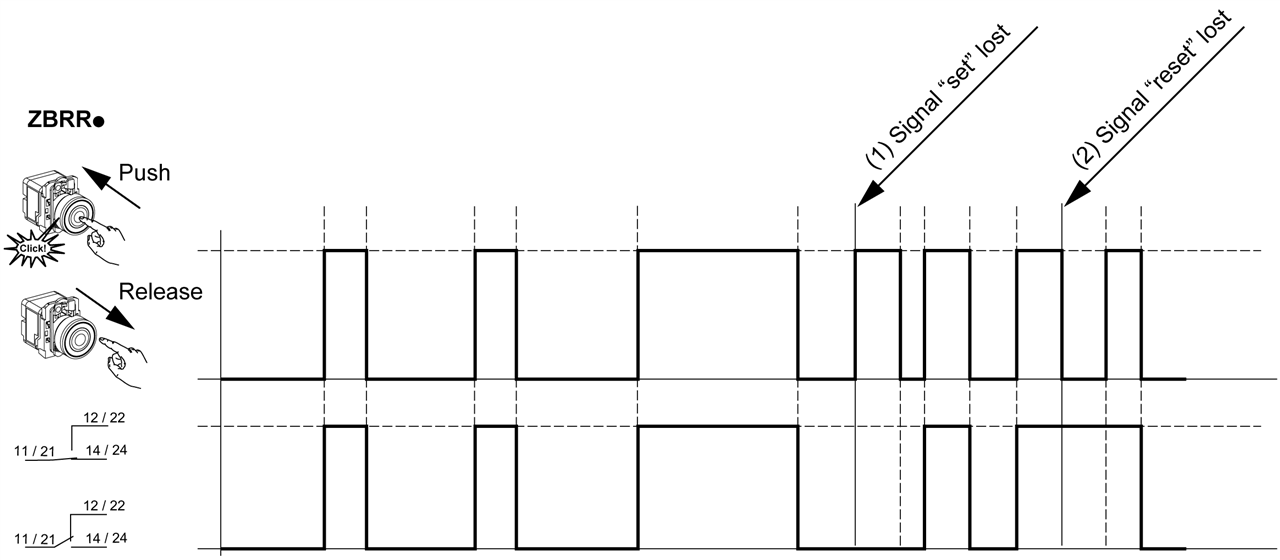
The battery less transmitter push button works with dynamo generator that converts mechanical energy into electrical energy by converting the push of the button. Hence, there is no need for battery or power supply to these devices.
There are two types of transmitters. ZBRT1 is the one where radio message is sent when button is pressed and for ZBRT2 radio message is sent when button is pressed as well as button is released.
HMIST6200 HMI MODULE
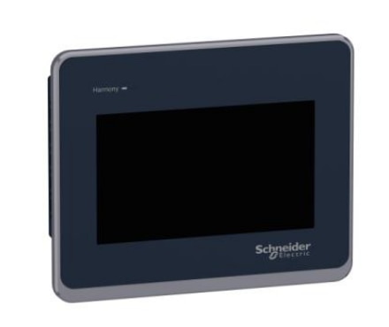
HMIST6200 HMI module from Schneider electric is HMI module with 4" LCD. It can be programmed using EcoStructure terminal expert GUI design software and various variable can also be transferred through PLC program running on EcoStructure machine expert. For example, sensor values can be transferred through PLC using software and can be displayed on screen. It has following features.
- Ethernet interface for transferring code
- Serial interface with RJ-45 connector
- USB type-A and type-B interface support
- 480 x 272 pixels resolution
- 16 million colours
A program can be uploaded to the device through the Ethernet port or through the USB interface.
Relay and socket
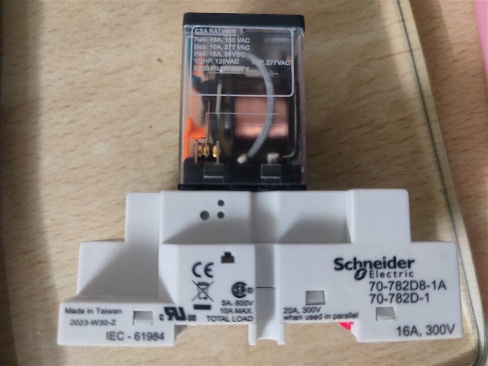
The relay contains two NO/NC connections. meaning two devices can be controlled through the relay. It comes with add on board to mount on DIN rails.
Planned system diagram
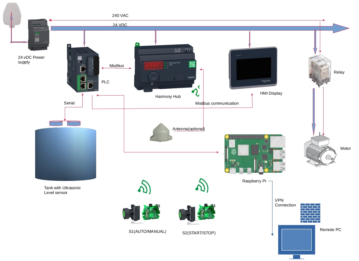
As I have mentioned all the parts and devices that are included in this package, now it is time to explain how I plan to used these devices in my project. The idea is that PLC will act as central controller that acts as a brain of the system. It will first connected to ultrasound sensor through some form of communication interface such as RS-485 or Modbus communication. The same PLC will communicate with Harmony hub to get the data received tirelessly from the push buttons and dynamo switches. PLC will also communicate with HMI to pass on correct sensor readings so that it can be displayed on LCD and users can provide some input through this display unit.
As the above diagram one can see two switches (S1 and S2). Both of these are used for user to have some control over the functionality of the project. First switch S1 will decide weather to use AUTO or MANUAL mode. In AUTO mode PLC will take care of when to start and stop the motor to keep the desired water level in the tank. HMI display can be used in this case to control the desired levels of water. The second switch(S2) can be used to start or stop the motor manually by user. User can start the motor whenever he/she want and stop as accordingly to fill the water tank. In this case HMI input is ignored or not required. The relay must be control with some form of excitation from the PLC.
Every major module in the diagram above is provided 24 VDC through the power supply connected to the mains supply. Motor and relay are provided power from the 240 VAC power supply.
Finally, A raspberry pi can be used to remotely monitor or access some of the PLC functionalities. This is not a mandatory requirement but will add some extra features on top of PLC functions.
Conclusion
As I have mentioned in this blog there are major parts already for designing the project. As the communication protocols play critical role, I need to learn how Modbus and other communication protocols functions with this devices in EcoStructure logic expert. The relay module also needs to be interface with some options. To conclude, I will still need to do work on software part of the project.
Reference
Schneider electric documentation.
https://www.se.com/in/en/download/doc-type/1555855-User+guide/
