element14 Community
element14 Community
    Register Log In
  • Site
  • Search
  • Log In Register
  • About Us
  • Community Hub
    Community Hub
    • What's New on element14
    • Feedback and Support
    • Benefits of Membership
    • Personal Blogs
    • Members Area
    • Achievement Levels
  • Learn
    Learn
    • Ask an Expert
    • eBooks
    • element14 presents
    • Learning Center
    • Tech Spotlight
    • STEM Academy
    • Webinars, Training and Events
    • Learning Groups
  • Technologies
    Technologies
    • 3D Printing
    • FPGA
    • Industrial Automation
    • Internet of Things
    • Power & Energy
    • Sensors
    • Technology Groups
  • Challenges & Projects
    Challenges & Projects
    • Design Challenges
    • element14 presents Projects
    • Project14
    • Arduino Projects
    • Raspberry Pi Projects
    • Project Groups
  • Products
    Products
    • Arduino
    • Avnet Boards Community
    • Dev Tools
    • Manufacturers
    • Multicomp Pro
    • Product Groups
    • Raspberry Pi
    • RoadTests & Reviews
  • Store
    Store
    • Visit Your Store
    • Choose another store...
      • Europe
      •  Austria (German)
      •  Belgium (Dutch, French)
      •  Bulgaria (Bulgarian)
      •  Czech Republic (Czech)
      •  Denmark (Danish)
      •  Estonia (Estonian)
      •  Finland (Finnish)
      •  France (French)
      •  Germany (German)
      •  Hungary (Hungarian)
      •  Ireland
      •  Israel
      •  Italy (Italian)
      •  Latvia (Latvian)
      •  
      •  Lithuania (Lithuanian)
      •  Netherlands (Dutch)
      •  Norway (Norwegian)
      •  Poland (Polish)
      •  Portugal (Portuguese)
      •  Romania (Romanian)
      •  Russia (Russian)
      •  Slovakia (Slovak)
      •  Slovenia (Slovenian)
      •  Spain (Spanish)
      •  Sweden (Swedish)
      •  Switzerland(German, French)
      •  Turkey (Turkish)
      •  United Kingdom
      • Asia Pacific
      •  Australia
      •  China
      •  Hong Kong
      •  India
      •  Korea (Korean)
      •  Malaysia
      •  New Zealand
      •  Philippines
      •  Singapore
      •  Taiwan
      •  Thailand (Thai)
      • Americas
      •  Brazil (Portuguese)
      •  Canada
      •  Mexico (Spanish)
      •  United States
      Can't find the country/region you're looking for? Visit our export site or find a local distributor.
  • Translate
  • Profile
  • Settings
Experimenting with Industrial Automation
  • Challenges & Projects
  • Design Challenges
  • Experimenting with Industrial Automation
  • More
  • Cancel
Experimenting with Industrial Automation
Blog Setting Up IO on M251 PLC Through ZBRN2 Harmony Hub - 3
  • Blog
  • Forum
  • Documents
  • Polls
  • Files
  • Members
  • Mentions
  • Sub-Groups
  • Tags
  • More
  • Cancel
  • New
Join Experimenting with Industrial Automation to participate - click to join for free!
  • Share
  • More
  • Cancel
Group Actions
  • Group RSS
  • More
  • Cancel
Engagement
  • Author Author: kmikemoo
  • Date Created: 23 Feb 2024 9:43 PM Date Created
  • Views 977 views
  • Likes 9 likes
  • Comments 3 comments
  • plc
  • experimenting with industrial automation
  • schneider electric
  • M251
  • ZBRN2
  • Harmony Hub
Related
Recommended

Setting Up IO on M251 PLC Through ZBRN2 Harmony Hub - 3

kmikemoo
kmikemoo
23 Feb 2024

Training Bay Ventilation Automation

This was my greatest challenge in the element14 Experimenting with Industrial Automation Design Challenge.  There are plenty of videos that tell one how to pair the switch modules (ZBRT2 transmitter module) to the Harmony Hub (ZBRN2).  There are instructions how to pair the receiver module (ZBRRH) to the Harmony Hub.  There are manuals that tell you what the MODBUS registers are in the Harmony Hub for every little thing on the paired transmitter input.  The paired receiver module (output) basically has the 16-bit word address for the four output of the paired receiver channel and the three values that make it OFF, Blink or ON.

Fantastic.     But for the beginner... how do you make it communicate?     <insert the sound of crickets here>

Step #1 of getting this system to exchange data is to start in the PLC Device Tree.  (View -> Navigators -> Device tree)
image

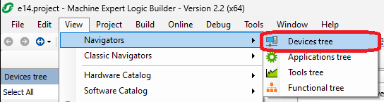
Go to Serial_Line_1 (Serial Line).  If you hoover your mouse pointer over the line, a green plus sign will appear at the right side.  Click on that.
image

Or you can go to the Serial_Line_1 (Serial Line).  Select the line.  Right click and Add Device.
image

Either way, you get the following screen.
image

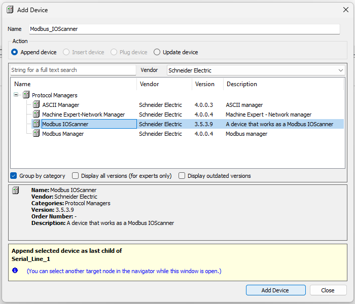
Select Modbus IOScanner and press the Add Device button in the lower right of the window.

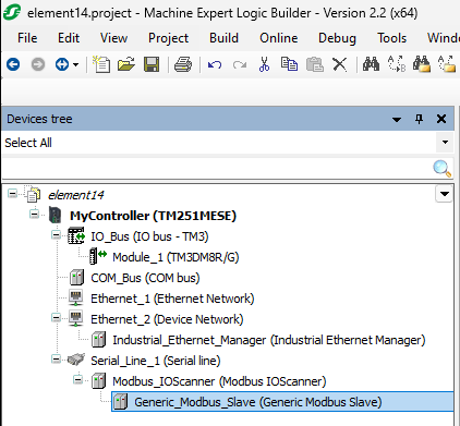
Back on the Device Tree, click on your newly added Modbus_IOScanner (Modbus IOScanner) line.  Right click.  Add Device.
image

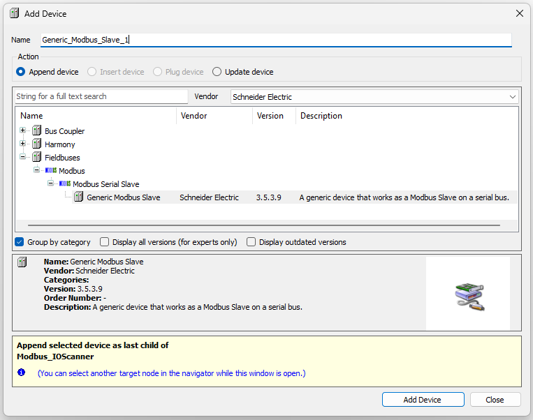
You can add the ZBRN2 from the Harmony folder.  I chose to add the Generic Modbus Slave.  Both work.  Click on Add Device button in the lower right of the window.
You will get one of the following based on your decision in the Device Tree.
image     image

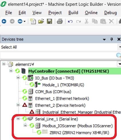
Configuring either the Generic_Modbus_Slave or the ZBRN2 will essentially be the same.  With the ZBRN2, you don't have to set up the inputs.  They are already added.  On both, you will need to add the output channel.
I chose to stay with the generic MODBUS slave only because it was the second one I tried to set up and it also worked - so I kept it.
Double click on the device you just added to configure it.

The first screen allows you to set the slave address programmed into the Harmony Hub (ZBRN2).  Since how to set this in the Harmony Hub (ZBRN2) is detailed in the Harmony Hub User Manual, I will not duplicate it here.  Slave address 1 is the default so it should not need to be changed anyway.
image

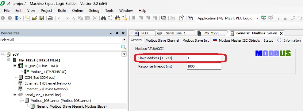
Next, you will need to add Modbus Slave Channels.  If you look at the picture above, you will see that there are two layers of tabs.  The lower ones are associated with the selected upper tab.  Select the Modbus Slave Channel.  Select Add Channel.  Fill in the details.  NOTE:  The offset is in HEX.  That really burned me for a few days because all the literature talks about it in decimal.     Also note that these windows have been resized a lot to get better screenshots.  Yours will be a lot more spread out.
image

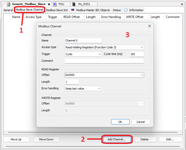
When you have added both the input and the output channels, you should see the screen below.
image

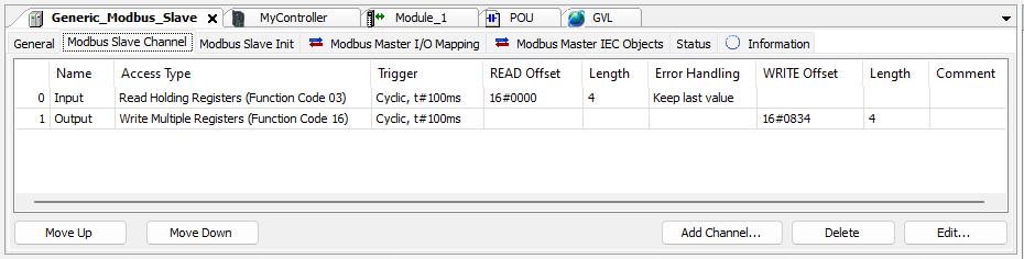
With this, you are ready to move to the Modbus Master I/O Mapping tab.
image

CONGRATULATIONS!  You now have addressable I/O.

For the output WORDs, 0 (zero) is OFF.  255 or 0xFF is ON.  0x5A is Blink, if that is what you would like.

I hope you find this useful.

  • Sign in to reply
Parents
  • embeddedguy
    embeddedguy over 1 year ago

    Informative blog. I will follow it once I am there.

    • Cancel
    • Vote Up 0 Vote Down
    • Sign in to reply
    • More
    • Cancel
Comment
  • embeddedguy
    embeddedguy over 1 year ago

    Informative blog. I will follow it once I am there.

    • Cancel
    • Vote Up 0 Vote Down
    • Sign in to reply
    • More
    • Cancel
Children
No Data
element14 Community

element14 is the first online community specifically for engineers. Connect with your peers and get expert answers to your questions.

  • Members
  • Learn
  • Technologies
  • Challenges & Projects
  • Products
  • Store
  • About Us
  • Feedback & Support
  • FAQs
  • Terms of Use
  • Privacy Policy
  • Legal and Copyright Notices
  • Sitemap
  • Cookies

An Avnet Company © 2025 Premier Farnell Limited. All Rights Reserved.

Premier Farnell Ltd, registered in England and Wales (no 00876412), registered office: Farnell House, Forge Lane, Leeds LS12 2NE.

ICP 备案号 10220084.

Follow element14

  • X
  • Facebook
  • linkedin
  • YouTube