


In the basement of my house there's an obsolete device hanging from one of the walls:
A Cable TV dispatcher / splitter, amplifier. With a few separate signal paths for bidirectional data (internet).
I've been looking at it for 6 years now. Time to look inside of it.
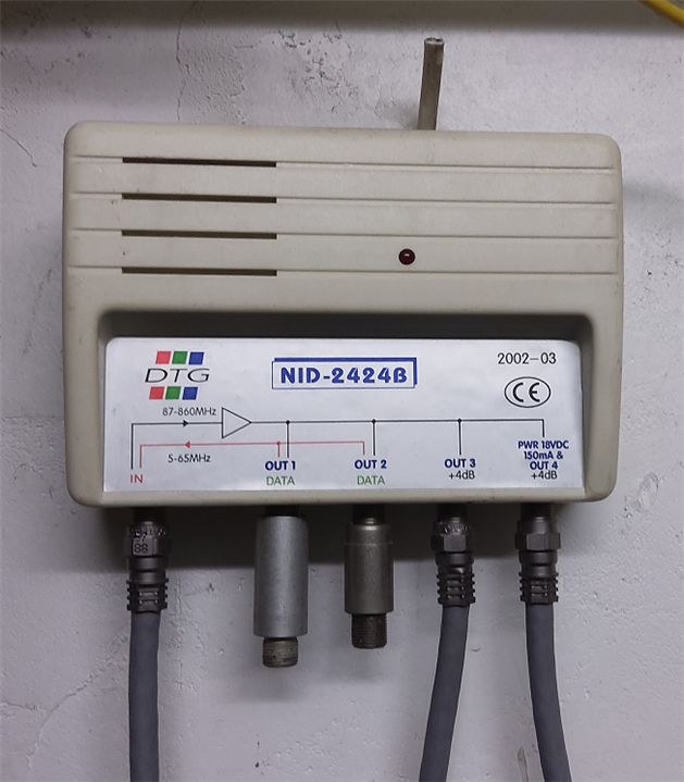
As you can see, the power connector has been cut off. I can safely assume that it's not in use anymore. My TV and internet enter via a different line, twisted pair.
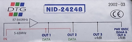
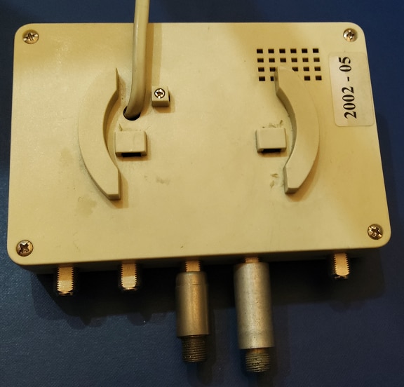
The front mentions 2002-03. There's a printed label on the backside with 2002-5.
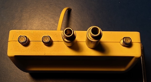
The connector on the left is Cable in.
The two next ones, for internet, are covered by a dummy. These are stubs that can only ne removed using special pliers (and by me :) ).
The last two ones are amplified TV signal. The last one includes a DC, so that it can optionally power an amplifier upstairs.
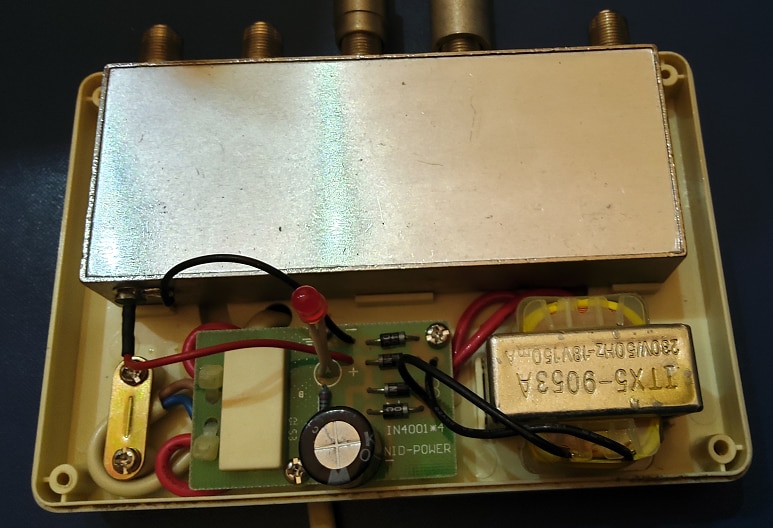
The whole set is not pretty. But it's well made. You'll see that it's of decent build inside too, in the photos below.
There are only two transistors. All other components are passives - and one relay.
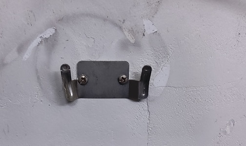
Wall mount and backside
Connectors and the two dummies / terminators
Inside
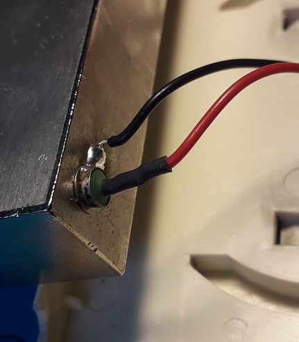
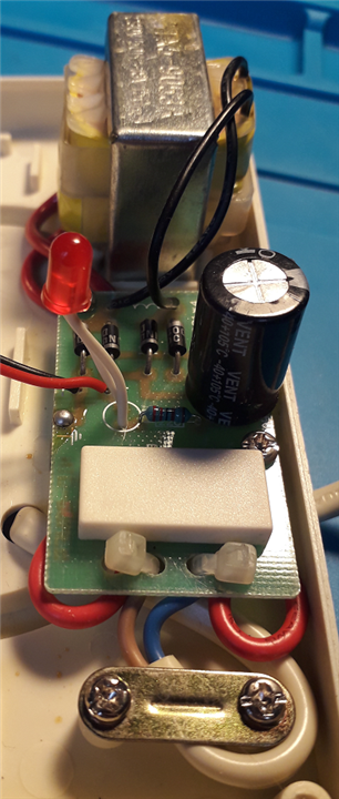
Penetrator for the power and details of the very simple supply
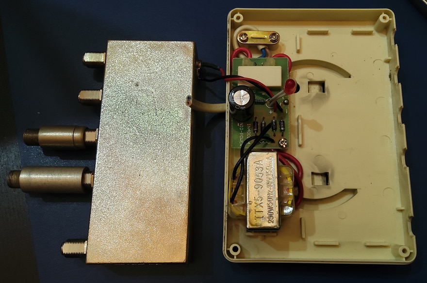
Shielded RF circuit with the connectors

Inside the can
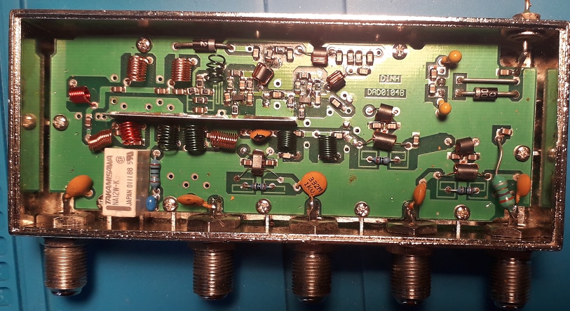
PCB top side
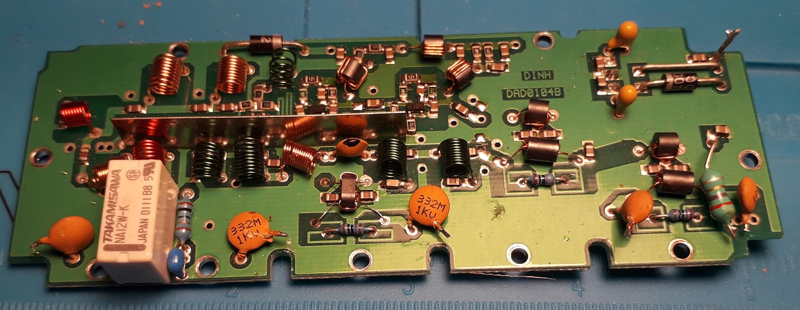
Active circuit
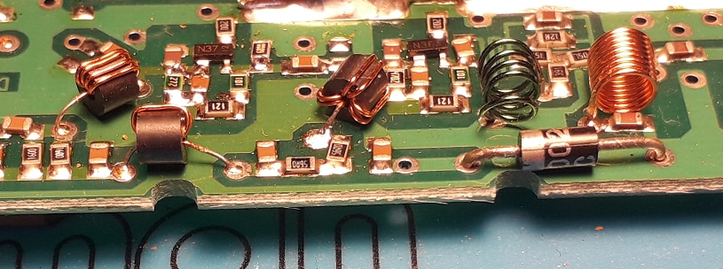
The SMDs seem to be place by hand.
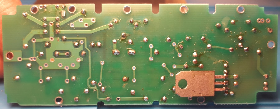
PCB Underside
I have more photos. But this should give an impression of how it's built.


