


When we work with RLC Circuits we need to know about Resonance and Low Pass and High Pass Filters
Let’s start Experimenting with Resonance.
What is Resonance in Electronics?
Resonance is a phenomenon that occurs in electric circuits consisting of capacitors and inductors. Resonance occurs when the capacitive impedance of the circuit is equal to the inductive impedance. Depending on the arrangement of the capacitors, inductors, and resistors, the conditions for achieving resonance varies between different types of circuits. There are two types of resonance Series resonance and Parallel Resonance.
Series Resonance
series resonance occurs when the arrangement of the components creates the minimum impedance.

Fig.1 Experimental setup of Series Resonance
In series resonance, the LC circuit exhibits maximum current response at a particular frequency i.e., Resonant frequency. The frequency of series resonance is obtained by the equation.

Ideal Graph

Fig 2 Ideal Graph of Series Resonance
I have tested series resonance as per Fig 1 and listed the outputs in the Tabular column.
For Experiment, signal generator Amplitude as kept to 2 Volts
| Serial No | Frequency In Hz | V out in Volts | I Max = Vout/R |
|---|---|---|---|
1 | 1 kHz | 1 V | 1.7mA |
| 2 | 2 kHz | 1.4V | 2.5 mA |
| 3 | 3 kHz | 1.8V | 3.2 mA |
| 4 | 4 kHz | 2V | 3.5 mA |
| 5 | 5 kHz | 2V | 3.5 mA |
| 6 | 6 kHz | 2V | 3.5 mA |
| 7 | 7 kHz | 2V | 3.5 mA |
| 8 | 8 kHz | 2V | 3.5 mA |
| 9 | 9 kHz | 2V | 3.5 mA |
| 10 | 10 KHz | 2V | 3.5 mA |
| 11 | 20 KHz | 2V | 3.5 mA |
| 12 | 100 KHz | 0.8V | 1.4 mA |
Bode Plot Graph for The Above Tabular Column

Fig 3 Bode Plot Series Resonance
Parallel Resonance
Parallel resonance occurs when the arrangement of components creates the largest impedance.

Fig 4 Parallel Resonance
When the circuit Is connected in parallel LC Circuits Exhibits Minimum current response at a particular Frequency.

Ideal Graph Of Parallel Resonance

Fig 5 Parallel Resonance Ideal Graph
I have tested series resonance as per Fig 4 and listed the outputs in the Tabular column.
For Experiment, signal generator Amplitude as kept to 2 Volts
| Serial No | Frequency In Hz | V out in Volts | I Max = Vout/R |
|---|---|---|---|
| 1 | 1 kHz | 1.8 V | 3.2 mA |
| 2 | 2 kHz | 1.8 V | 3.2 mA |
| 3 | 3 kHz | 1.8 V | 3.2 mA |
| 4 | 4 kHz | 1.8 V | 3.2 mA |
| 5 | 5 kHz | 1.8 V | 3.2 mA |
| 6 | 6 kHz | 1.8 V | 3.2 mA |
| 7 | 7 kHz | 1.6 V | 2.8 mA |
| 8 | 8 kHz | 1.6 V | 2.8 mA |
| 9 | 9 kHz | 1.3 V | 2.32 mA |
| 10 | 10 kHz | 0. 8 V | 1.4 mA |
| 11 | 11 kHz | 0.6 V | 1 mA |
| 12 | 12 kHz | 1.1 V | 1.9 mA |
| 13 | 13 kHz | 1.5 V | 2.6 mA |
| 14 | 19 KHZ | 1.8 V | 3.2 mA |
Bode Plot Graph for The Above Tabular Column

Fig 6 Parallel Resonance Bode Plot
LC Filters
Low Pass Filter (LPF)
Low Pass Filter is used to filter out unwanted signals that may be present in a band above the wanted passband. In this way, this form of filter only accepts signals below the cut-off frequency.LC Low pass filter is also called a Passive low pass 2nd order. A 2nd order low pass does basically the same function as its 1st order counterpart but has twice as much slope. So low frequencies can happen while high frequencies are filtered twice as effectively. The difference is caused by the coil. As an inductive load, it reacts much faster to voltage changes than an ohmic resistance.

Fig 7 LC LPF Circuit
LC low pass – how it works
The function of the capacitor is exactly the same as in the low-pass 1st order. It is located exactly in the same place and the output voltage is tapped identically. The response to a single, erratic change in input voltage is also comparable. The coil has resistance near zero as long as a DC voltage is applied.
The difference only becomes apparent when a changing voltage is applied. The coil is more responsive to the increase in frequency than an ohmic resistance. As the frequency increases, the inductive reactance of the coil XL increases while the capacitance XC of the capacitor decreases. Thus, changes in the frequency at the input are reflected even more clearly in the level of the output voltage.
Calculate cutoff frequency at LC low pass
The inductive resistance XL increases with frequency while the capacitive reactance XC is inversely proportional to it – it decreases as the frequency increases. The cutoff frequency is the frequency at which XC=XL. Thus, at a frequency greater than the cutoff frequency, XC is less than XL. At a lower frequency, XC is greater than XL.
The cutoff frequency for an LC low pass is calculated using the following formula:

High Pass Filter (HPF)
LC HPF Is also called a Passive second order high pass filter.

A 2nd order high pass filters the low frequencies twice as effectively as a 1st order high pass. The edge is twice as steep. The difference comes from the coil, which, unlike the capacitor, reacts quickly to high frequencies.
LC high pass operation
The function of the capacitor remains unchanged. At a low-frequency input voltage, it forms a high capacitive reactance XC. A sudden change, therefore, causes a momentary voltage spike at the output, because the capacitor’s reaction is delayed.
When applying a sinusoidal voltage, however, the coil fulfills its purpose. The capacitor forms a resistor at low frequencies and allows high frequencies through. The coil, on the other hand, reacts immediately to an increase in frequency and forms an inductive reactance XL. In contrast to the capacitor, their resistance increases together with the frequency. This ensures a faster and stronger response to frequency increases.
Calculate the cutoff frequency of 2nd order high pass
As described above, capacitive and inductive reactance always change in opposite directions. At the cutoff frequency, the resistors are identical. It is, therefore: XL=XC. At a higher frequency, therefore, XC>XL and at a lower frequency XC<XL.
The formula for calculating the cutoff frequency is:

For The Design Challenge, I have Proposed Noise Power Supply and Distribution Circuit.
I Have designed the circuit with line filters, Low Pass Filters, Buck-Boost Converter. To observe the noise during High Load I have used the high current inductors along with the MOSFET.
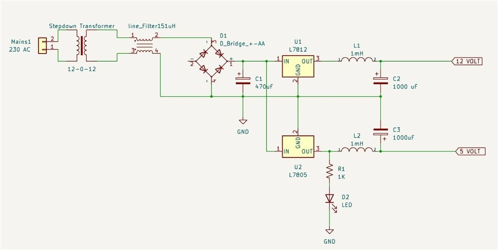
Figure above is the only AC -DC Converter With 12- and 5-Volt Output.

The Below Waveform Is Direct Output of the Transformer

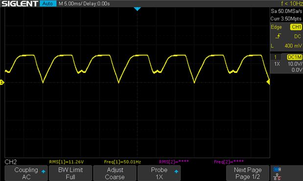
The Line Filter Output Waveform

Bridge Rectifier Output Waveform Without Capacitor Filter
Bridge Rectifier Output Waveform with Capacitor Filter

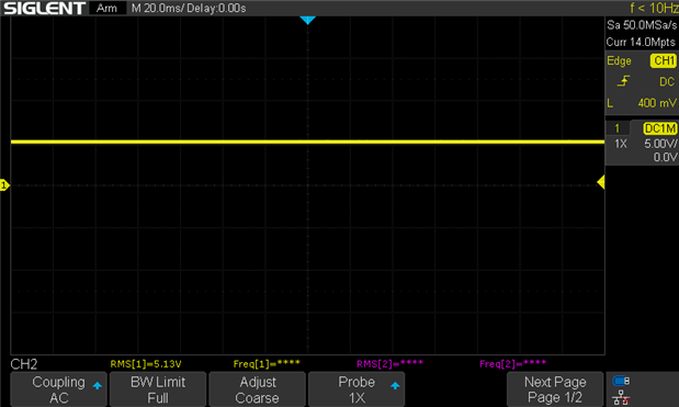
5 Volt Voltage Regulator with LC Filter
12 Volt Voltage Regulator with LC Filter

To Analyze the Noise During the Load, Here I have used Inductors.
We know that we can’t directly use the Inductive load with the Power supply and Voltage Regulators. So, I have created a Load driving circuit with the help of a PWM Generator, MOSFET Drivers, And MOSFETS.
PWM Generator
To generate the Variable Pulse Width with Variable Frequency I have used SG3525 IC along with other Passive Components. in this circuit width of the signal and frequency of the signal can adjust using Individual Potentiometers.

MOSFET Driver
To drive the individual MOSFET Using PWM Signals I am using IRS2110 IC Along with the other passive Components. The MOSFET Driver Has Two Driving channels.
MOSFETS
For the experiments, I have used the N channel and P channel MOSFETS.
IRF540 – N Channel
IRF9540 – P Channel
In the below pictures you can see the Circuit of Inductance LOAD Driving

SG3525 PWM Generator Oscillator Output

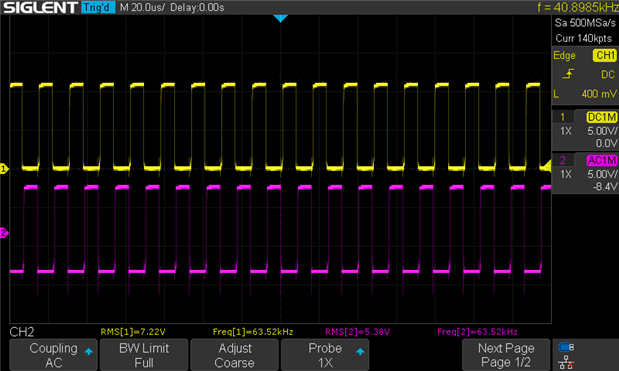
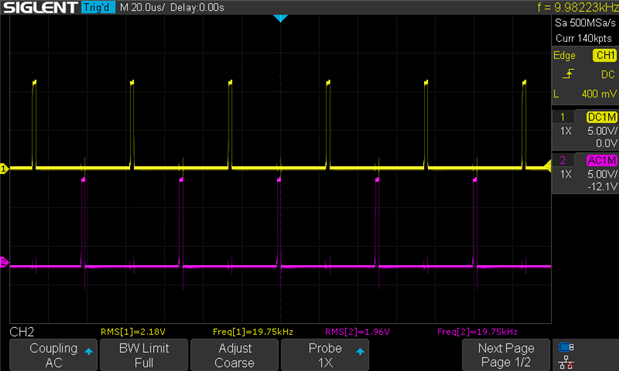
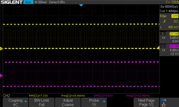
PWM Generator OUTPUT “A” AND “B”

PWM Generator OUTPUT “A” AND “B” Low Pulse Width
Output Of IRS2110
Output Of IRS2110

Output Of IRS2110 When The inductor is added to MOSFET.

BUCK-BOOST CONVERTER CIRCUIT
To test the noise in the Buck-boost conversion I have created the Circuit.

Buck Converter Output
To step down the voltage I have used the Buck converter mode in the Circuit. I had planned to reduce the voltage just by 2 Volt and the results are as expected.

Boost Converter Output
To step up the voltage I have used the Boost converter mode in the Circuit. I had planned to increase the voltage just by 5 Volt and the results are as expected.

Buck-Boost Converter output video