


Contents -
1. Introduction
2. Ideal vs Practical behavior of an Inductor
3. SRF, RDC and Q factor
4. Experiments (Part 2)
Introduction
In the first blog of the Experimenting with Magnetic Components, I'll talk about one of the three basic components of electronics - The inductor and where the idea of my proposal Ideal vs Real inductors came from.
A little technical background before I start with the blog. I have been working with electronics since last 8 years. I started as a hobbyist and today I'm pursuing a masters in RF and Microwave engineering. Since, childhood days, I picked up interest in RF and I would try making lot of wireless transmitters (FM/AM). However, none of them worked as almost every circuit needed an inductor (an air core one) and due to lack of measuring instruments, I couldn't make proper valued inductors but I thought it should with any coil.
By that time, I hadn't realized the importance of choosing the right inductor.
But today as I often need inductors to bias a p-i-n diode and other active RF components, I realized that choosing the right inductor is very important for the RF circuit to work. One of the applications of inductors is as a RFCs in RF circuits to bias the active RF component (diode, BJT, FET, etc) and to block the RF from flowing into the DC power supply.
The figure below shows the RF biasing circuit used for biasing a p-i-n diode to be used as a SPST switch (Image Courtesy : Infineon)
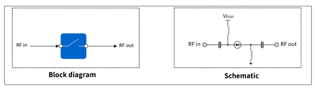
In the above figure, the inductor from Vbias provides a DC bias to the diode at the same time it should block the RF from flowing into the Vbias power supply.
But how to choose this RFC or inductor? What parameters should be looked at while choosing an RFC? Let's understand this from some simple mathematical equations and a little bit of theory.
Ideal vs Practical behavior of an Inductor
Let's understand what is the purpose of RFC first. An RFC is used to provide a DC bias to the device. For example, in the above figure, the p-i-n diode is used as an RF switch. A diode needs DC bias to switch ON/OFF. When the diode is forwards biased, it will pass the RF in to RF out port acting as ON, when the diode is reverse biased, it will provide isolation between RF in and RF out ports acting as OFF. At the same time, the RF current should not flow into the power supply as it might damage the supply. Hence, an inductor is used here as an inductor works as a short circuit for DC and provides an impedance to AC or RF proportional to the frequency (does it?).
Since, the inductor has to block the RF from going in to the DC supply, it should provide a high impedance. This impedance is given by
XL=2πƒ L
where,
XL = Reactance/Impedance of inductor (in ohms)
f = frequency
L = inductance value (1mH)
From the above equation, it is evident that for a fixed value of inductance, with increase in frequency, the reactance/impedance provided by the inductor should increase linearly.
The below figure shows a plot of Impedance vs Frequency (in MHz). It can be seen that the impedance increases linearly with frequency. This is the ideal behavior of an inductor.
However, if you perform this experiment practically, you'll find that the experimental result doesn't match with the theory. Why? 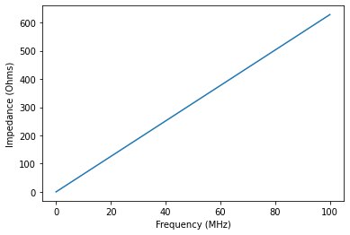
Because as we move to higher frequencies, the parasitics of the inductor come into picture.
Let's take a look at the datasheet of one of the inductors from the Kit provided as a part of the challenge. I'm choosing the Bourns 1mH inductor from the kit.
It is seen that each inductor comes with a SRF and RDC.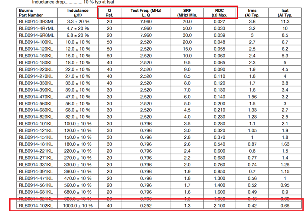
SRF, RDC and Q factor
SRF stands for self resonance frequency and RDC stands for the DC resistance provided by the inductor coil. These two values come from the parasitic behavior of the inductor at a given frequency.
The figure below shows the parasitic model of an inductor which is the real inductor (the deviation from ideal inductor) (Image courtesy : RF Circuit Design Theory And Application Second Edition)
From the figure it can be seen that due to the coil, there will be a parasitic capacitance between each turn of the coil and the wire from which the coil is made will also have some resistance. Together with the inductor, this model of the inductor is shown in above figure. 
Since, there is a parasitic capacitor, this inductor will resonate at a certain frequency and this frequency is known as the self resonance frequency of the inductor. The RDC comes from the wire and is responsible for the losses in the inductor.
The figure below shows how the impedance of ideal inductor vs a real inductors varies with frequency (Image courtesy : RF Circuit Design Theory And Application Second Edition).
While choosing an inductor as RFC it is important to check the SRF. As it is seen from the above plot that the behavior of the practical inductor deviates from ideal nature and can only provide a maximum impedance to RF at the SRF. 
This happens because with all the parasitics the inductor behaves as a parallel LC circuit and a parallel LC circuit can provide max impedance at resonance and it will behave as inductive at frequencies lower than resonance frequency and as a capacitive circuit at frequencies higher than resonance frequency.
For the above LC circuit, the impedance is given by - 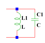
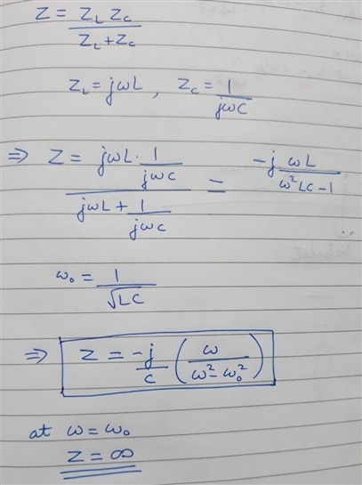
As there is a resistor present in the model, the impedance won't be infinite. Finally, due to the presence of RDC and lossy nature of inductor, each inductor has a Q factor.
Q factor is the ratio of impedance and RDC.
In the next part of the blog, I'll show how to extract the values of these parasitics experimentally and perform certain experiments to evaluate the inductors from the kit, plot the impedance vs frequency charts, calculate the SRF, RDC and Q factor.
Acknowledgement: I would like to thank the element14 team and Bourns for organizing the challenge and sponsoring the kit.


