


Table of Contents
Introduction
Greetings Element14 community! This is my second blog post for the Experimenting with Sensor Fusion competition!
After nearly two months of design, the competition is now coming to an end, and today I would like to share with you my entry and take a deep dive into how everything works!
Now without further ado, let's explore the enigmatic field of sensor fusion!
Project Description (Recap)
The goal of this competition is to implement some kind of sensor fusion application. Sensor fusion is the process of collecting data from a variety of sensors and combining them in a useful manner.
At a high level, I want to be able to collect data from an IMU so that I can calculate the pose of a rigid body and then represent it as a coordinate frame on a live camera feed.
The gallery below shows what the coordinate frame visualization will look like.
| Drone Pose Visualization Examples |
|---|
|
Drone Pose: ωx=3.6 ωy=1.78 ωz=2.2 (rad) |

Note 1: The axis is projected with the following rotation to give perspective: ωx=0.2 ωy=0.785398 ωz=0.1 (rad).
Note 2: Blue = x-axis, Red=y-axis, Green=z-axis.
Design Process
Last blog, I created a task breakdown to describe what all needed to be done in order for the project to be successful. For the most part, I did not deviate from that list during the design process. The one exception to that was in regards to the IMU processing. I kind of treated that as "another day" problem and greatly underestimated how involved that step would be, and because I saved that part until the end, a lot of things crashed and burned. Despite that, things did turn out alright in the end, it was just a bit stressful because it was too late to redesign a lot of things. I just want to make the disclaimer, that there are a lot of things I would do differently now that I better understand the IMU side of things.
Task #1: Implement an unaccelerated OpenCV application which handles the pose graphics.
The code below is very similar to what I used to generate the example images in my last blog. I didn't revision control this project very well, so there might be some small differences. There are two main functions that I'm interested in: cv::projectPoints and cv::line. cv::ProjectPoints does all the mathematical heavy lifting and cv::line does all the graphics. The purpose of cv::projectPoints is to convert 3D coordinates to 2D coordinates. The OpenCV implementation has lots of special features like distortion handling, but in my case, since I'm just overlaying onto a screen, I can assume zero distortion. The cv::line function is kind of interesting in that it is really a combination of two functions. One function draws a 2D rectangle and another function draws two circles at each end of the rectangle to round off the edges. What's interesting about this is that even though you pass two points into the cv::line function, internally the cv::line function actually needs to know about six points: four points for four the corners of the rectangle and two points for the midpoint at each end of the rectangle where the circle gets drawn.
int main()
{
    std::vector<double> T, R{1,0,0,0,1,0,0,0,1};
    double cols, rows, R_cols, R_rows;
    int i, j;
    cv::Mat rvec = cv::Mat::zeros(1,3,CV_64F), rot_mat = cv::Mat::zeros(3,3,CV_64F);

    // Store Rotation Matrix in vector
    for(i=0; i<3; i++)
    {
        for(j=0; j<3; j++)
            rot_mat.at<double>(i,j) = R[i*3+j];
    }

    // Print Rotation Matrix
    printf("Rotation Matrix:\n");
    for(i=0; i<3; i++)
    {
        for(j=0; j<3; j++)
            printf("% f ", rot_mat.at<double>(i,j));
        printf("\n");
    }
    printf("\n");

    // Print Rodriques Matrix -> Vector
    printf("Rodriques: ");
    Rodrigues(rot_mat, rvec);
    for(i=0; i<3; i++)
        printf("% f ", rvec.at<double>(i));
    printf("\n");
    rvec.at<double>(0)=0.2      + 3.6;//about x
    rvec.at<double>(1)=0.785398 + 1.78;//about y
    rvec.at<double>(2)=0.1      + 2.2;//about z

    //cv::Mat axis_rvec(rvec);
    cv::Mat axis_rvec = cv::Mat::zeros(1,3,CV_64F), axis_rot_mat = cv::Mat::zeros(3,3,CV_64F);
    Rodrigues(axis_rot_mat, axis_rvec);
    axis_rvec.at<double>(0)=0.2;//about x
    axis_rvec.at<double>(1)=0.785398;//about y
    axis_rvec.at<double>(2)=0.1;//about z

    // Create 3D points
    std::vector<cv::Point3d> objectPoints = {
    cv::Point3d(1,0,0),
    cv::Point3d(0,1,0),
    cv::Point3d(0,0,1),
    cv::Point3d(0,0,0)
    };

    std::vector<cv::Point3d> axisPoints = {
    cv::Point3d(1.5,0,0),
    cv::Point3d(0,1.5,0),
    cv::Point3d(0,0,1.5),
    cv::Point3d(-1.5,0,0),
    cv::Point3d(0,-1.5,0),
    cv::Point3d(0,0,-1.5)
    };

    // rvec

    // tvec
    cv::Mat tvec(3, 1, cv::DataType<double>::type); // Translation vector
    tvec.at<double>(0) = 0;
    tvec.at<double>(1) = 0;
    tvec.at<double>(2) = 1*SCALE;

    // cameraMatrix
    cv::Mat cameraMatrix(3, 3, cv::DataType<double>::type); // Intrisic matrix
    cameraMatrix = cv::Mat::eye(3,3,CV_64FC1);
    cameraMatrix.at<double>(0,2) = 960;//x0
    cameraMatrix.at<double>(1,2) = 540;//y0
    cameraMatrix.at<double>(0,0) = 1000;//fx
    cameraMatrix.at<double>(1,1) = 1000;//fy
    //cameraMatrix.at<double>(0,1) = 100;//s
    std::cout << "Intrisic matrix: " << cameraMatrix << std::endl << std::endl;

    // distCoeffs
    cv::Mat distCoeffs(5, 1, cv::DataType<double>::type);   // Distortion vector
    distCoeffs.at<double>(0) = 0;
    distCoeffs.at<double>(1) = 0;
    distCoeffs.at<double>(2) = 0;
    distCoeffs.at<double>(3) = 0;
    distCoeffs.at<double>(4) = 0;
    distCoeffs.at<double>(5) = 0;
    distCoeffs.at<double>(6) = 0;
    distCoeffs.at<double>(7) = 0;
    distCoeffs.at<double>(8) = 0;
    distCoeffs.at<double>(9) = 0;
    distCoeffs.at<double>(10) = 0;
    distCoeffs.at<double>(11) = 0;
    distCoeffs.at<double>(12) = 0;
    distCoeffs.at<double>(13) = 0;
    distCoeffs.at<double>(14) = 0;

    // imagePoints
    std::vector<cv::Point2d> imagePoints;
    std::vector<cv::Point2d> aimagePoints;

    // Create projection
    cv::projectPoints(objectPoints, rvec, tvec, cameraMatrix, imagePoints);
    cv::projectPoints(axisPoints, axis_rvec, tvec, cameraMatrix, aimagePoints);

    // White background
    cv::Mat img(1080, 1920, CV_8UC3, cv::Scalar(255, 255, 255));

    int thickness = 10;

    cv::Point ap1 = aimagePoints[0], ap4 = aimagePoints[3];
    cv::Point ap2 = aimagePoints[1], ap5 = aimagePoints[4];
    cv::Point ap3 = aimagePoints[2], ap6 = aimagePoints[5];
    line(img, ap1, ap4, cv::Scalar(0, 0, 0),
         thickness/4, cv::LINE_8);
    line(img, ap2, ap5, cv::Scalar(0, 0, 0),
         thickness/4, cv::LINE_8);
    line(img, ap3, ap6, cv::Scalar(0, 0, 0),
         thickness/4, cv::LINE_8);

    cv::Point p1 = imagePoints[0], p2 = imagePoints[1];
    cv::Point p3 = imagePoints[2], p4 = imagePoints[3];
    line(img, p1, p4, cv::Scalar(255, 0, 0),
         thickness, cv::LINE_8);
    line(img, p2, p4, cv::Scalar(0, 255, 0),
         thickness, cv::LINE_8);
    line(img, p3, p4, cv::Scalar(0, 0, 255),
         thickness, cv::LINE_8);


    cv::imwrite("cv_fitline.png", img);
    return 0;
}
Task #2: Simplify the OpenCV functions.
The goal of using OpenCV is to have a known good algorithm which we can using Vitis HLS. OpenCV is very verbose, however, and draws functions from many different files which can make it difficult to accelerate functions. The goal of this next step is to locate the source code for cv::projectPoints and cv::line and get rid of their corresponding OpenCV headers. We want all the source code in one file so that we can simplify it. You will see that this is messy code and a lot of the functions are renamed (ie projectPoints to projectPointss), but now this file is very self-contained and you can start to understand what the code is actually doing.
namespace cv
{

int cvRodrigues2_(const Mat* src, CvMat* dst)
{
    Point3d r;
    r.x = src->at<double>(0);
    r.y = src->at<double>(1);
    r.z = src->at<double>(2);

    double theta = sqrt(r.x*r.x+r.y*r.y+r.z*r.z);//double theta = norm(r);

    if( theta < DBL_EPSILON )
    {
        cvSetIdentity( dst );
    }
    else
    {
        double c = cos(theta);
        double s = sin(theta);
        double c1 = 1. - c;
        double itheta = theta ? 1./theta : 0.;

        r *= itheta;

        Matx33d rrt( r.x*r.x, r.x*r.y, r.x*r.z, r.x*r.y, r.y*r.y, r.y*r.z, r.x*r.z, r.y*r.z, r.z*r.z );
        Matx33d r_x(    0, -r.z,  r.y,
                      r.z,    0, -r.x,
                     -r.y,  r.x,    0 );

        Matx33d R = c*Matx33d::eye() + c1*rrt + s*r_x;

        Mat(R).convertTo(cvarrToMat(dst), dst->type);
    }


    return 1;
}


void cvProjectPoints22( const Mat* objectPoints,
                  const Mat* r_vec,
                  const Mat* t_vec,
                  const Mat* A,
                  Mat* imagePoints)
{
    double R[9];
    CvMat matR = cvMat( 3, 3, CV_64F, R );
    cvRodrigues2_(r_vec, &matR);

    double fx, fy, cx, cy;
    fx = A->at<double>(0); fy = A->at<double>(4);
    cx = A->at<double>(2); cy = A->at<double>(5);

    for(int i = 0; i < objectPoints->cols; i++)
    {
        double X = objectPoints->at<cv::Point3d>(i).x;
        double Y = objectPoints->at<cv::Point3d>(i).y;
        double Z = objectPoints->at<cv::Point3d>(i).z;
        double x = R[0]*X + R[1]*Y + R[2]*Z + t_vec->at<double>(0);
        double y = R[3]*X + R[4]*Y + R[5]*Z + t_vec->at<double>(1);
        double z = R[6]*X + R[7]*Y + R[8]*Z + t_vec->at<double>(2);
        z = z ? 1./z : 1;
        x *= z; y *= z;
        imagePoints->at<cv::Point2d>(i) = cv::Point2d(x*fx + cx, y*fy + cy);
    }
}


void projectPointss( InputArray _opoints,
                        InputArray _rvec,
                        InputArray _tvec,
                        InputArray _cameraMatrix,
                        OutputArray _ipoints)
{
    _ipoints.create(_opoints.getMat().checkVector(3), 1, CV_MAKETYPE(_opoints.getMat().depth(), 2), -1, true);
    Mat objectPoints = _opoints.getMat();
    Mat imagePoints = _ipoints.getMat();
    Mat cameraMatrix = _cameraMatrix.getMat();
    Mat rvec = _rvec.getMat();
    Mat tvec = _tvec.getMat();

    cvProjectPoints22(&objectPoints, &rvec, &tvec, &cameraMatrix, &imagePoints);
}

}// END NAMESPACE CV


enum { XY_SHIFT = 16, XY_ONE = 1 << XY_SHIFT, DRAWING_STORAGE_BLOCK = (1<<12) - 256 };
static const int MAX_THICKNESS = 32767;
namespace cv
{

static inline void ICV_HLINE(uchar* ptr, int xl, int xr, const void* color, int pix_size)
{
    for (int i = xl*3; i <= xr*3; i+=3) {
        memcpy(ptr+i, reinterpret_cast<const uchar*>(color), pix_size);
    }
}

static void
FillConvexPolyy( Mat& img, const Point2l* v, int npts, const void* color, int line_type, int shift )
{
    struct
    {
        int idx, di;
        int64 x, dx;
        int ye;
    }
    edge[2];

    int delta = 1 << shift >> 1;
    int i, y, imin = 0;
    int edges = npts;
    int64 xmin, xmax, ymin, ymax;
    uchar* ptr = img.ptr();
    Size size = img.size();
    int pix_size = (int)img.elemSize();
    Point2l p0;
    int delta1, delta2;

    delta1 = delta2 = XY_ONE >> 1;

    p0 = v[npts - 1];
    p0.x <<= XY_SHIFT - shift;
    p0.y <<= XY_SHIFT - shift;

    assert( 0 <= shift && shift <= XY_SHIFT );
    xmin = xmax = v[0].x;
    ymin = ymax = v[0].y;

    for( i = 0; i < npts; i++ )
    {
        Point2l p = v[i];
        if( p.y < ymin )
        {
            ymin = p.y;
            imin = i;
        }

        ymax = std::max( ymax, p.y );
        xmax = std::max( xmax, p.x );
        xmin = MIN( xmin, p.x );

        p.x <<= XY_SHIFT - shift;
        p.y <<= XY_SHIFT - shift;


        p0 = p;
    }

    xmin = (xmin + delta) >> shift;
    xmax = (xmax + delta) >> shift;
    ymin = (ymin + delta) >> shift;
    ymax = (ymax + delta) >> shift;

    ymax = MIN( ymax, size.height - 1 );
    edge[0].idx = edge[1].idx = imin;

    edge[0].ye = edge[1].ye = y = (int)ymin;
    edge[0].di = 1;
    edge[1].di = npts - 1;

    edge[0].x = edge[1].x = -XY_ONE;
    edge[0].dx = edge[1].dx = 0;

    ptr += img.step*y;

    do
    {
        if( line_type < CV_AA || y < (int)ymax || y == (int)ymin )
        {
            for( i = 0; i < 2; i++ )
            {
                if( y >= edge[i].ye )
                {
                    int idx0 = edge[i].idx, di = edge[i].di;
                    int idx = idx0 + di;
                    if (idx >= npts) idx -= npts;
                    int ty = 0;

                    for (; edges-- > 0; )
                    {
                        ty = (int)((v[idx].y + delta) >> shift);
                        if (ty > y)
                        {
                            int64 xs = v[idx0].x;
                            int64 xe = v[idx].x;
                            if (shift != XY_SHIFT)
                            {
                                xs <<= XY_SHIFT - shift;
                                xe <<= XY_SHIFT - shift;
                            }

                            edge[i].ye = ty;
                            edge[i].dx = ((xe - xs)*2 + (ty - y)) / (2 * (ty - y));
                            edge[i].x = xs;
                            edge[i].idx = idx;
                            break;
                        }
                        idx0 = idx;
                        idx += di;
                        if (idx >= npts) idx -= npts;
                    }
                }
            }
        }

        if (edges < 0)
            break;

        if (y >= 0)
        {
            int left = 0, right = 1;
            if (edge[0].x > edge[1].x)
            {
                left = 1, right = 0;
            }

            int xx1 = (int)((edge[left].x + delta1) >> XY_SHIFT);
            int xx2 = (int)((edge[right].x + delta2) >> XY_SHIFT);

            if( xx2 >= 0 && xx1 < size.width )
            {
                if( xx1 < 0 )
                    xx1 = 0;
                if( xx2 >= size.width )
                    xx2 = size.width - 1;
                ICV_HLINE( ptr, xx1, xx2, color, pix_size );
            }
        }
        else
        {
            // TODO optimize scan for negative y
        }

        edge[0].x += edge[0].dx;
        edge[1].x += edge[1].dx;
        ptr += img.step;
    }
    while( ++y <= (int)ymax );
}


/* draws simple or filled circle */
static void
Circlee( Mat& img, Point center, int radius, const void* color, int fill )
{
    Size size = img.size();
    size_t step = img.step;
    int pix_size = (int)img.elemSize();
    uchar* ptr = img.ptr();
    int err = 0, dx = radius, dy = 0, plus = 1, minus = (radius << 1) - 1;
    int inside = center.x >= radius && center.x < size.width - radius &&
        center.y >= radius && center.y < size.height - radius;

    #define ICV_PUT_POINT( ptr, x )     \
        memcpy( ptr + (x)*pix_size, color, pix_size );

    while( dx >= dy )
    {
        int mask;
        int y11 = center.y - dy, y12 = center.y + dy, y21 = center.y - dx, y22 = center.y + dx;
        int x11 = center.x - dx, x12 = center.x + dx, x21 = center.x - dy, x22 = center.x + dy;

        if( inside )
        {
            uchar *tptr0 = ptr + y11 * step;
            uchar *tptr1 = ptr + y12 * step;

            if( !fill )
            {
                ICV_PUT_POINT( tptr0, x11 );
                ICV_PUT_POINT( tptr1, x11 );
                ICV_PUT_POINT( tptr0, x12 );
                ICV_PUT_POINT( tptr1, x12 );
            }
            else
            {
                ICV_HLINE( tptr0, x11, x12, color, pix_size );
                ICV_HLINE( tptr1, x11, x12, color, pix_size );
            }

            tptr0 = ptr + y21 * step;
            tptr1 = ptr + y22 * step;

            if( !fill )
            {
                ICV_PUT_POINT( tptr0, x21 );
                ICV_PUT_POINT( tptr1, x21 );
                ICV_PUT_POINT( tptr0, x22 );
                ICV_PUT_POINT( tptr1, x22 );
            }
            else
            {
                ICV_HLINE( tptr0, x21, x22, color, pix_size );
                ICV_HLINE( tptr1, x21, x22, color, pix_size );
            }
        }
        else if( x11 < size.width && x12 >= 0 && y21 < size.height && y22 >= 0 )
        {
            if( fill )
            {
                x11 = std::max( x11, 0 );
                x12 = MIN( x12, size.width - 1 );
            }

            if( (unsigned)y11 < (unsigned)size.height )
            {
                uchar *tptr = ptr + y11 * step;

                if( !fill )
                {
                    if( x11 >= 0 )
                        ICV_PUT_POINT( tptr, x11 );
                    if( x12 < size.width )
                        ICV_PUT_POINT( tptr, x12 );
                }
                else
                    ICV_HLINE( tptr, x11, x12, color, pix_size );
            }

            if( (unsigned)y12 < (unsigned)size.height )
            {
                uchar *tptr = ptr + y12 * step;

                if( !fill )
                {
                    if( x11 >= 0 )
                        ICV_PUT_POINT( tptr, x11 );
                    if( x12 < size.width )
                        ICV_PUT_POINT( tptr, x12 );
                }
                else
                    ICV_HLINE( tptr, x11, x12, color, pix_size );
            }

            if( x21 < size.width && x22 >= 0 )
            {
                if( fill )
                {
                    x21 = std::max( x21, 0 );
                    x22 = MIN( x22, size.width - 1 );
                }

                if( (unsigned)y21 < (unsigned)size.height )
                {
                    uchar *tptr = ptr + y21 * step;

                    if( !fill )
                    {
                        if( x21 >= 0 )
                            ICV_PUT_POINT( tptr, x21 );
                        if( x22 < size.width )
                            ICV_PUT_POINT( tptr, x22 );
                    }
                    else
                        ICV_HLINE( tptr, x21, x22, color, pix_size );
                }

                if( (unsigned)y22 < (unsigned)size.height )
                {
                    uchar *tptr = ptr + y22 * step;

                    if( !fill )
                    {
                        if( x21 >= 0 )
                            ICV_PUT_POINT( tptr, x21 );
                        if( x22 < size.width )
                            ICV_PUT_POINT( tptr, x22 );
                    }
                    else
                        ICV_HLINE( tptr, x21, x22, color, pix_size );
                }
            }
        }
        dy++;
        err += plus;
        plus += 2;

        mask = (err <= 0) - 1;

        err -= minus & mask;
        dx += mask;
        minus -= mask & 2;
    }

    #undef  ICV_PUT_POINT
}

static void
ThickLinee( Mat& img, Point2l p0, Point2l p1, const void* color,
           int thickness, int line_type)
{
    static const double INV_XY_ONE = 1./XY_ONE;

    p0.x <<= XY_SHIFT;
    p0.y <<= XY_SHIFT;
    p1.x <<= XY_SHIFT;
    p1.y <<= XY_SHIFT;

    Point2l pt[4], dp = Point2l(0,0);
    double dx = (p0.x - p1.x)*INV_XY_ONE, dy = (p1.y - p0.y)*INV_XY_ONE;
    double r = dx * dx + dy * dy;
    int i, oddThickness = thickness & 1;
    thickness <<= XY_SHIFT - 1;

    if( fabs(r) > DBL_EPSILON )
    {
        r = (thickness + oddThickness*XY_ONE*0.5)/std::sqrt(r);
        dp.x = cvRound( dy * r );
        dp.y = cvRound( dx * r );

        pt[0].x = p0.x + dp.x;
        pt[0].y = p0.y + dp.y;
        pt[1].x = p0.x - dp.x;
        pt[1].y = p0.y - dp.y;
        pt[2].x = p1.x - dp.x;
        pt[2].y = p1.y - dp.y;
        pt[3].x = p1.x + dp.x;
        pt[3].y = p1.y + dp.y;

        FillConvexPolyy( img, pt, 4, color, line_type, XY_SHIFT );
    }

    for( i = 0; i < 2; i++ )
    {
        if( line_type < CV_AA )
        {
            Point center;
            center.x = (int)((p0.x + (XY_ONE>>1)) >> XY_SHIFT);
            center.y = (int)((p0.y + (XY_ONE>>1)) >> XY_SHIFT);
            Circle( img, center, (thickness + (XY_ONE>>1)) >> XY_SHIFT, color, 1 );
        }
        p0 = p1;
    }
}
}// END NAMESPACE CV


// ~/Documents/VitisHLS/Libraries/opencv-3.4.15/modules/imgproc/src/drawing.cpp (line 1773)
void linee( cv::Mat img, cv::Point pt1, cv::Point pt2, const cv::Scalar& color,
           int thickness, int line_type )
{

    char buf[4];
    for(int i = 0; i < CV_MAT_CN(img.type()); i++) {
        buf[i] = color.val[i];
    }
    ThickLinee( img, pt1, pt2, buf, thickness, line_type);
}


#include <opencv2/calib3d/calib3d.hpp>

#define SCALE 7

int main()
{
    //std::vector<double> T, R{0,-1,0,1,0,0,0,0,1};
    std::vector<double> T, R{1,0,0,0,1,0,0,0,1};
    //std::vector<double> T, R{0.5,-0.1465,0.8535,0.5,0.8535,-0.1465,-0.7072,0.5,0.5};
    //std::vector<double> T, R{0.75,-0.2166,0.625,0.433,0.875,-0.2166,-0.5,0.433,0.75};
    double cols, rows, R_cols, R_rows;
    int i, j;
    cv::Mat rvec = cv::Mat::zeros(1,3,CV_64F), rot_mat = cv::Mat::zeros(3,3,CV_64F);

    // Store Rotation Matrix in vector
    for(i=0; i<3; i++)
    {
        for(j=0; j<3; j++)
            rot_mat.at<double>(i,j) = R[i*3+j];
    }

    // Print Rotation Matrix
    printf("Rotation Matrix:\n");
    for(i=0; i<3; i++)
    {
        for(j=0; j<3; j++)
            printf("% f ", rot_mat.at<double>(i,j));
        printf("\n");
    }
    printf("\n");

    // Print Rodriques Matrix -> Vector
    printf("Rodriques: ");
    Rodrigues(rot_mat, rvec);
    for(i=0; i<3; i++)
        printf("% f ", rvec.at<double>(i));
    printf("\n");
    rvec.at<double>(0)=0.2      + 3.6;//about x
    rvec.at<double>(1)=0.785398 + 1.78;//about y
    rvec.at<double>(2)=0.1      + 2.2;//about z

    //cv::Mat axis_rvec(rvec);
    cv::Mat axis_rvec = cv::Mat::zeros(1,3,CV_64F), axis_rot_mat = cv::Mat::zeros(3,3,CV_64F);
    Rodrigues(axis_rot_mat, axis_rvec);
    axis_rvec.at<double>(0)=0.2;//about x
    axis_rvec.at<double>(1)=0.785398;//about y
    axis_rvec.at<double>(2)=0.1;//about z

    // Create 3D points
    std::vector<cv::Point3d> objectPoints = {
    cv::Point3d(1,0,0),
    cv::Point3d(0,1,0),
    cv::Point3d(0,0,1),
    cv::Point3d(0,0,0)
    };

    std::vector<cv::Point3d> axisPoints = {
    cv::Point3d(1.5,0,0),
    cv::Point3d(0,1.5,0),
    cv::Point3d(0,0,1.5),
    cv::Point3d(-1.5,0,0),
    cv::Point3d(0,-1.5,0),
    cv::Point3d(0,0,-1.5)
    };

    // rvec

    // tvec
    cv::Mat tvec(3, 1, cv::DataType<double>::type); // Translation vector
    tvec.at<double>(0) = 0;
    tvec.at<double>(1) = 0;
    tvec.at<double>(2) = 1*SCALE;

    // cameraMatrix
    cv::Mat cameraMatrix(3, 3, cv::DataType<double>::type); // Intrisic matrix
    cameraMatrix = cv::Mat::eye(3,3,CV_64FC1);
    cameraMatrix.at<double>(0,2) = 960;//x0
    cameraMatrix.at<double>(1,2) = 540;//y0
    cameraMatrix.at<double>(0,0) = 1000;//fx
    cameraMatrix.at<double>(1,1) = 1000;//fy
    //cameraMatrix.at<double>(0,1) = 100;//s
    std::cout << "Intrisic matrix: " << cameraMatrix << std::endl << std::endl;

    // distCoeffs
    cv::Mat distCoeffs(5, 1, cv::DataType<double>::type);   // Distortion vector
    distCoeffs.at<double>(0) = 0;
    distCoeffs.at<double>(1) = 0;
    distCoeffs.at<double>(2) = 0;
    distCoeffs.at<double>(3) = 0;
    distCoeffs.at<double>(4) = 0;
    distCoeffs.at<double>(5) = 0;
    distCoeffs.at<double>(6) = 0;
    distCoeffs.at<double>(7) = 0;
    distCoeffs.at<double>(8) = 0;
    distCoeffs.at<double>(9) = 0;
    distCoeffs.at<double>(10) = 0;
    distCoeffs.at<double>(11) = 0;
    distCoeffs.at<double>(12) = 0;
    distCoeffs.at<double>(13) = 0;
    distCoeffs.at<double>(14) = 0;

    // imagePoints
    std::vector<cv::Point2d> imagePoints;
    std::vector<cv::Point2d> aimagePoints;

    // Create projection
    //cv::projectPoints(objectPoints, rvec, tvec, cameraMatrix, distCoeffs, imagePoints);
    cv::projectPointss(objectPoints, rvec, tvec, cameraMatrix, imagePoints);
    cv::projectPointss(axisPoints, axis_rvec, tvec, cameraMatrix, aimagePoints);

    //cv::Mat img = cv::imread("/sensor_fusion/manual/vitis_hls/line/src/input.png");
    //cv::Mat img = cv::imread("/sensor_fusion/manual/vitis_hls/line/src/black_background.png");
    cv::Mat img(1080, 1920, CV_8UC3, cv::Scalar(255, 255, 255));

    int thickness = 10;

    cv::Point ap1 = aimagePoints[0], ap4 = aimagePoints[3];
    cv::Point ap2 = aimagePoints[1], ap5 = aimagePoints[4];
    cv::Point ap3 = aimagePoints[2], ap6 = aimagePoints[5];
    linee(img, ap1, ap4, cv::Scalar(0, 0, 0),
         thickness/4, cv::LINE_8);
    linee(img, ap2, ap5, cv::Scalar(0, 0, 0),
         thickness/4, cv::LINE_8);
    linee(img, ap3, ap6, cv::Scalar(0, 0, 0),
         thickness/4, cv::LINE_8);

    cv::Point p1 = imagePoints[0], p2 = imagePoints[1];
    cv::Point p3 = imagePoints[2], p4 = imagePoints[3];
    linee(img, p1, p4, cv::Scalar(255, 0, 0),
         thickness, cv::LINE_8);
    linee(img, p2, p4, cv::Scalar(0, 255, 0),
         thickness, cv::LINE_8);
    linee(img, p3, p4, cv::Scalar(0, 0, 255),
         thickness, cv::LINE_8);


    cv::imwrite("cv_fitline.png", img);
    return 0;
}
When looking at the code, you will begin to notice some things that present algorithmic challenges. For example, the graphics drawing functions (cv::line, cv::ThickLine, cv::Circle) , all call a macro called ICV_HLINE. The purpose of this macro is to draw horizontal lines in an image. Once the algorithm reaches a certain condition, it will attempt to fill in multiple pixels at once in loop. Unfortunately, this presents a problem since we want our graphics accelerator to sit in line with our AXI4-Stream interfaces which operate at 1PPC (pixel per clock). The way these drawing algorithms are written, you need to process multiple pixels at once, but this can't be done in the context of an AXI4-Stream interface. This means, I will have to implement my own graphics algorithm.
Luckily, however, the cv::projectPoints algorithm can be implemented exactly as is. To simplify it further, I rewrote cv::projectPoints so that it doesn't use any of the OpenCV API.
struct point2d
{
    int x;
    int y;
};
struct point3d
{
    double x;
    double y;
    double z;
};

int cvRodrigues2__(const double* r_vec, double* R)
{
    struct point3d r;
    r.x = r_vec[0];
    r.y = r_vec[1];
    r.z = r_vec[2];

    double theta = sqrt(r.x*r.x+r.y*r.y+r.z*r.z);//double theta = norm(r);

    double I[9]= {1,0,0,0,1,0,0,0,1};

    if( theta < DBL_EPSILON )
    {
        for (int i = 0; i < 9; i++) R[i] = I[i];
    }
    else
    {
        double c = cos(theta);
        double s = sin(theta);
        double c1 = 1. - c;
        double itheta = theta ? 1./theta : 0.;

        r.x *= itheta;
        r.y *= itheta;
        r.z *= itheta;

        double rrt[9] = {r.x*r.x, r.x*r.y, r.x*r.z, r.x*r.y, r.y*r.y, r.y*r.z, r.x*r.z, r.y*r.z, r.z*r.z};

        double r_x[9] = {0, -r.z, r.y, r.z, 0, -r.x,-r.y, r.x, 0};

        for (int i = 0; i < 9; i++) R[i] = c*I[i]+c1*rrt[i]+s*r_x[i];

    }

    return 1;
}

void projectPoints( const int count,
                    const struct point3d objectPoints[6],
                    const double r_vec[3],
                    const double t_vec[3],
                    const double A[3][3],
                    struct point2d imagePoints[6] )
{
    double R[9];
    cvRodrigues2__(r_vec, R);

    double fx, fy, cx, cy;
    fx = A[0][0]; fy = A[1][1];
    cx = A[0][2]; cy = A[1][2];

    for(int i = 0; i < count/*objectPoints->cols*/; i++)
    {
        double X = objectPoints[i].x;
        double Y = objectPoints[i].y;
        double Z = objectPoints[i].z;
        double x = R[0]*X + R[1]*Y + R[2]*Z + t_vec[0];
        double y = R[3]*X + R[4]*Y + R[5]*Z + t_vec[1];
        double z = R[6]*X + R[7]*Y + R[8]*Z + t_vec[2];
        z = z ? 1./z : 1;
        x *= z; y *= z;
        imagePoints[i].x = x*fx + cx;
        imagePoints[i].y = y*fy + cy;
    }
}

#define SCALE 7
#include <time.h>
int mainn()
{
    double rvec[3];

    rvec[0]=0.2      + 3.6;//about x
    rvec[1]=0.785398 + 1.78;//about y
    rvec[2]=0.1      + 2.2;//about z

    double axis_rvec[3];
    axis_rvec[0]=0.2;//about x
    axis_rvec[1]=0.785398;//about y
    axis_rvec[2]=0.1;//about z

    // Create 3D points
    struct point3d objectPoints[4] =
    {
    	{1,0,0},
    	{0,1,0},
    	{0,0,1},
    	{0,0,0}
    };

    struct point3d axisPoints[6] = {
    	{1.5,0,0},
		{0,1.5,0},
		{0,0,1.5},
		{-1.5,0,0},
		{0,-1.5,0},
		{0,0,-1.5}
    };

    // rvec

    // tvec
    double tvec[3]; // Translation vector
    tvec[0] = 0;
    tvec[1] = 0;
    tvec[2] = 1*SCALE;

    // cameraMatrix
    double cameraMatrix[3][3]; // Intrinsic matrix
    cameraMatrix[0][0] = 1;
    cameraMatrix[0][1] = 1;
    cameraMatrix[0][2] = 1;
    cameraMatrix[1][0] = 1;
    cameraMatrix[1][1] = 1;
    cameraMatrix[1][2] = 1;
    cameraMatrix[2][0] = 1;
    cameraMatrix[2][1] = 1;
    cameraMatrix[2][2] = 1;
    cameraMatrix[0][2] = 960;//x0
    cameraMatrix[1][2] = 540;//y0
    cameraMatrix[0][0] = 1000;//fx
    cameraMatrix[1][1] = 1000;//fy
    //cameraMatrix[0][1] = 100;//s

    // imagePoints
    struct point2d imagePoints[4];
    struct point2d aimagePoints[6];

    // Create projection
clock_t start = clock() ;
    projectPoints(4, objectPoints, rvec, tvec, cameraMatrix, imagePoints);
    projectPoints(6, axisPoints, axis_rvec, tvec, cameraMatrix, aimagePoints);
clock_t end = clock() ;
double elapsed_time = (end-start)/(double)CLOCKS_PER_SEC ;
printf("%10.10f\r\n", elapsed_time);

    //struct point2d ap1 = aimagePoints[0], ap4 = aimagePoints[3];
    //struct point2d ap2 = aimagePoints[1], ap5 = aimagePoints[4];
    //struct point2d ap3 = aimagePoints[2], ap6 = aimagePoints[5];

    //struct point2d p1 = imagePoints[0], p2 = imagePoints[1];
    //struct point2d p3 = imagePoints[2], p4 = imagePoints[3];

//
//
//

    cv::Mat img(1080, 1920, CV_8UC3, cv::Scalar(255, 255, 255));

    int thickness = 10;

    cv::Point ap1(aimagePoints[0].x,aimagePoints[0].y);
    cv::Point ap2(aimagePoints[1].x,aimagePoints[1].y);
    cv::Point ap3(aimagePoints[2].x,aimagePoints[2].y);
    cv::Point ap4(aimagePoints[3].x,aimagePoints[3].y);
    cv::Point ap5(aimagePoints[4].x,aimagePoints[4].y);
    cv::Point ap6(aimagePoints[5].x,aimagePoints[5].y);
    linee(img, ap1, ap4, cv::Scalar(0, 0, 0),
         thickness/4, cv::LINE_8);
    linee(img, ap2, ap5, cv::Scalar(0, 0, 0),
         thickness/4, cv::LINE_8);
    linee(img, ap3, ap6, cv::Scalar(0, 0, 0),
         thickness/4, cv::LINE_8);

    cv::Point p1(imagePoints[0].x,imagePoints[0].y);
    cv::Point p2(imagePoints[1].x,imagePoints[1].y);
    cv::Point p3(imagePoints[2].x,imagePoints[2].y);
    cv::Point p4(imagePoints[3].x,imagePoints[3].y);
    linee(img, p1, p4, cv::Scalar(255, 0, 0),
         thickness, cv::LINE_8);
    linee(img, p2, p4, cv::Scalar(0, 255, 0),
         thickness, cv::LINE_8);
    linee(img, p3, p4, cv::Scalar(0, 0, 255),
         thickness, cv::LINE_8);


    cv::imwrite("cv_fitline.png", img);

    return 0;
}
When I run cv::projectPoints on an x86 machine, it takes 0.0003140000s. This is actually plenty fast, so I decided to profile the function on a Microblaze processor on the SP701 FPGA.
#include "e14.h"

int TmrCtrInit(XTmrCtr *TmrCtrInstPtr,
			   u16 DeviceId,
			   u8 TmrCtrNumber)
{
	int Status;

	// Initialize the timer counter
	Status = XTmrCtr_Initialize(TmrCtrInstPtr, DeviceId);
	if (Status != XST_SUCCESS) {
		return XST_FAILURE;
	}

	// Perform a self-test to ensure that the hardware was built correctly
	Status = XTmrCtr_SelfTest(TmrCtrInstPtr, TmrCtrNumber);
	if (Status != XST_SUCCESS) {
		return XST_FAILURE;
	}

	return XST_SUCCESS;
}

void print_elasped_time(XTmrCtr *TmrCtrInstPtr, u16 DeviceId)
{
	u32 cycles = XTmrCtr_GetValue(TmrCtrInstPtr, DeviceId);
	float ns = (float) cycles / XPAR_MICROBLAZE_CORE_CLOCK_FREQ_HZ;
	int ns_whole = ns;
	int ns_billionths = (ns - ns_whole) * 1e9;
	xil_printf("%d.%09d\n", ns_whole, ns_billionths);
}

#include <float.h>
#include <math.h>

#define SCALE 7

struct point2d
{
    int x;
    int y;
};
struct point3d
{
    double x;
    double y;
    double z;
};

int cvRodrigues2(const double* r_vec, double* R)
{
    struct point3d r;
    r.x = r_vec[0];
    r.y = r_vec[1];
    r.z = r_vec[2];

    double theta = sqrt(r.x*r.x+r.y*r.y+r.z*r.z);//double theta = norm(r);

    double I[9]= {1,0,0,0,1,0,0,0,1};

    if( theta < DBL_EPSILON )
    {
        for (int i = 0; i < 9; i++) R[i] = I[i];
    }
    else
    {
        double c = cos(theta);
        double s = sin(theta);
        double c1 = 1. - c;
        double itheta = theta ? 1./theta : 0.;

        r.x *= itheta;
        r.y *= itheta;
        r.z *= itheta;

        double rrt[9] = {r.x*r.x, r.x*r.y, r.x*r.z, r.x*r.y, r.y*r.y, r.y*r.z, r.x*r.z, r.y*r.z, r.z*r.z};

        double r_x[9] = {0, -r.z, r.y, r.z, 0, -r.x,-r.y, r.x, 0};

        for (int i = 0; i < 9; i++) R[i] = c*I[i]+c1*rrt[i]+s*r_x[i];

    }

    return 1;
}

void projectPoints( const int count,
                    const struct point3d objectPoints[6],
                    const double r_vec[3],
                    const double t_vec[3],
                    const double A[3][3],
                    struct point2d imagePoints[6] )
{
    double R[9];
    cvRodrigues2(r_vec, R);

    double fx, fy, cx, cy;
    fx = A[0][0]; fy = A[1][1];
    cx = A[0][2]; cy = A[1][2];

    for(int i = 0; i < count/*objectPoints->cols*/; i++)
    {
        double X = objectPoints[i].x;
        double Y = objectPoints[i].y;
        double Z = objectPoints[i].z;
        double x = R[0]*X + R[1]*Y + R[2]*Z + t_vec[0];
        double y = R[3]*X + R[4]*Y + R[5]*Z + t_vec[1];
        double z = R[6]*X + R[7]*Y + R[8]*Z + t_vec[2];
        z = z ? 1./z : 1;
        x *= z; y *= z;
        imagePoints[i].x = x*fx + cx;
        imagePoints[i].y = y*fy + cy;
    }
}

void profile_projectPoints()
{
    // Create 3D points
    struct point3d objectPoints[4] =
    {
    	{1,0,0},
    	{0,1,0},
    	{0,0,1},
    	{0,0,0}
    };

    struct point3d axisPoints[6] = {
    	{1.5,0,0},
		{0,1.5,0},
		{0,0,1.5},
		{-1.5,0,0},
		{0,-1.5,0},
		{0,0,-1.5}
    };

    // rvec
    double rvec[3];
    rvec[0]=0.2      + 3.6;//about x
    rvec[1]=0.785398 + 1.78;//about y
    rvec[2]=0.1      + 2.2;//about z

    double axis_rvec[3];
    axis_rvec[0]=0.2;//about x
    axis_rvec[1]=0.785398;//about y
    axis_rvec[2]=0.1;//about z

    // tvec
    double tvec[3]; // Translation vector
    tvec[0] = 0;
    tvec[1] = 0;
    tvec[2] = 1*SCALE;

    // cameraMatrix
    double cameraMatrix[3][3]; // Intrinsic matrix
    cameraMatrix[0][0] = 1;
    cameraMatrix[0][1] = 1;
    cameraMatrix[0][2] = 1;
    cameraMatrix[1][0] = 1;
    cameraMatrix[1][1] = 1;
    cameraMatrix[1][2] = 1;
    cameraMatrix[2][0] = 1;
    cameraMatrix[2][1] = 1;
    cameraMatrix[2][2] = 1;
    cameraMatrix[0][2] = 960;//x0
    cameraMatrix[1][2] = 540;//y0
    cameraMatrix[0][0] = 1000;//fx
    cameraMatrix[1][1] = 1000;//fy
    //cameraMatrix[0][1] = 100;//s

    // imagePoints
    struct point2d imagePoints[4];
    struct point2d aimagePoints[6];

    // Create projection
XTmrCtr_Start(&TmrCtrInst, TMRCTR_DEVICE_ID);
    projectPoints(4, objectPoints, rvec, tvec, cameraMatrix, imagePoints);
    projectPoints(6, axisPoints, axis_rvec, tvec, cameraMatrix, aimagePoints);
XTmrCtr_Stop(&TmrCtrInst, TMRCTR_DEVICE_ID);
print_elasped_time(&TmrCtrInst, TMRCTR_DEVICE_ID);
}
Unfortunately, the results were less than stellar. It took about 1.113468885s to execute on the Microblaze processor. The main reason it takes so long is because there is no floating point unit (FPU). Even if one was enabled, I was concerned about the preformance, so I decided that it would be best to implement this as a Vitis HLS kernel.
Task #3: Accelerate the OpenCV functions
Time for the fun part, this is why we're all here right? I went through a ton of iterations to get these to work, and it would take too long to go over all the design choices, but I want to give a high level overview of the history of this design.
Originally I tried to implement everything inside one AXI4-Stream accelerator. This worked really well for the graphics functions (ie cv::line), but I encountered a lot of problems with the projectPoints function. cv::projectPoints takes a lot longer to execute and it was hard for it to achieve a low initiation interval (II) to keep up with the graphics functions. Ultimately, I had to give up on the idea because I was using something like 20000 LUT's and 50 DSP.
This is when I came up with the idea to implement three different accelerators.
Accelerator 1: CoordinateFrame (aka CF).
Accelerator 2: ProjectPoints (aka PP).
Accelerator 2: MadgwickNav (aka MN).
The CF accelerator handles all the graphics functions. This is a very stupid graphic function because I wrote the algorithm. It needs to be given the four points for each rectangle as well as the center and radius for each circle. I wrote a custom function called in_convex and in_circle which are fairly efficient at determining whether the current point in an AXI4-stream is within a region or not
The PP accelerator takes the accelerometer data in the form of a euclidean rotation vector [rx,ry,rz] to rotate a list of unit vectors representing the axes of the coordinate frame in 3D space and then projects them into 2D space. The PP accelerator also takes the two-point representation of each axis and converts them to a rectangle with a radius, r, which can be used by the CF accelerator. I wanted to avoid polluting each accelerator with graphics-specific implementations, but I really needed a way to offload some of the computation in the CF accelerator since it has a much stricter deadline with the AXI4-Stream interface.
The MN accelerator is something that I haven't talked about at all really because my intent was never to make it an accelerator until I realized that I had to. The purpose of this accelerator is to to fuse the raw IMU data from the accelerometer, gyroscope, and magnetometer to get a euclidean rotation vector [rx,ry,rz] also known as roll, pitch, and yaw. This accelerator was implemented using the de facto standard.
Take a look at the gallery below to see the Vitis HLS "top level function" for each accelerator and the meaning of each variable.
| Vitis HLS Top Level Functions |
|---|
 Coordinate Frame Accelerator _src and _dst = the input and output image frame (don't think cv::Mat, think 1PPC AXI4-Stream interface) r = radius r_en = rectangle enable c_en = circle enable ip[0:4]_{x,y} = coordinate frame image points (the origin, and the end point of each axis) {x,y,z}_axis_rectangle_p[0:3]_{x,y} = the four points that form the rectangle of each axis |
|
Project Points Accelerator r{x,y,z} = the rotation about the x, y, and z axis x0, y0 = sets the camera matrix origin, this is where the coordinate frame origin will be as well fx, fy = sets the camera matrix focal length, this makes objects appear closer or farther than they are tz = this is the translation about the z-axis, a true representation of the 3D coordinate position before projection r = the radius of the rectangle for each axis that you are projecting (note this function does overlap with some of the cv::line features) z_fg[0:2] = this returns the z coordinate of each axis endpoint (useful so you can draw lines in layer order from background to foreground if they overlap) ip[0:4]_{x,y} = this returns the coordinate frame image points (the origin, and the end point of each axis) {x,y,z}_axis_rectangle_p[0:3]_{x,y} = this returns the four points that form the rectangle of each axis |
|
g_range = the range of the accelerometer's raw values (g-force) dps_range = the range of the gyroscope's raw values (degress per second) gauss_range = the range of the magnetometer's raw values (gauss) ai{z,y,z} = raw sample of the accelerometer (linear accelerations) across the x, y, and z axis gi{x,y,z} = raw sample of the gyroscope (angular accelerations) about the x, y, and z axis mi{x,y,z} = raw sample of the magnetometer (gauss accelerations? I don't pretend to know) upon the x, y, and z axis |


When implementing the MN and PP accelerators, I found that I was constantly fighting Vitis HLS to use fewer resources. I never could quite find a way to truly slow down the functions to use less resources. My workaround was generally to inline and allocate as few resources as possible by using pragmas like the ones below:
// Used mostly for MadgwickNav and ProjectPoints
#pragma HLS INLINE
#pragma HLS INLINE recursive

#pragma HLS ALLOCATION operation instances=dmul limit=1
#pragma HLS ALLOCATION operation instances=fmul limit=1
#pragma HLS ALLOCATION operation instances=mul limit=1
#pragma HLS ALLOCATION operation instances=dadd limit=1
#pragma HLS ALLOCATION operation instances=fadd limit=1
#pragma HLS ALLOCATION operation instances=add limit=1
#pragma HLS ALLOCATION operation instances=dsub limit=1
#pragma HLS ALLOCATION operation instances=fsub limit=1
#pragma HLS ALLOCATION operation instances=sub limit=1
#pragma HLS ALLOCATION operation instances=fsqrt limit=1
For the CF accelerator, my strategy was a little different since it has a much higher throughput. We are processing a 1080p image at 30Hz at 1 PPC. This means the data rate is 1920*1080*30 or about 62MP/s (mega pixels per second). After playing around with a lot of initiation intervals (II), I decided to go with an II=3 and setting the AXI4-Stream interface to 200MHz. By setting the intitiation interval to three, the cycle count becomes 62MP/s * 3 cycles/(MP/s) or about 186MHz. This means a 200MHz clock is safe to use.
RowLoop:
    for (i = 0; i < height; i++) {
// clang-format off
        #pragma HLS LOOP_FLATTEN off
        #pragma HLS LOOP_TRIPCOUNT min=ROWS max=ROWS
    // clang-format on
    ColLoop:
        for (j = 0; j < width; j++) {
// clang-format off
            #pragma HLS LOOP_TRIPCOUNT min=TC max=TC
			#pragma HLS pipeline II=3
Each accelerator has four files associated with it, using the following convention: {CF,MN,PP}_{tb,config,accel,impl}. The _tb file is for testbenches. The _config file is to constrain certain aspects of the design such as image size. The _accel file is for the top level function and dataflow regions. The _impl file is for sub-functions with specialized pragmas, such as getting pipelined or inlined. These files make up the core of the FPGA implementation.
// CF_tb.cpp

#include "common/xf_headers.hpp"
#include "common/xf_axi.hpp"

#include "CF_config.h"

#include <opencv2/imgproc/imgproc.hpp>
#include <iostream>

cv::Mat tb_expected(cv::Mat img);

int main(int argc, char** argv) {
    cv::Mat img = cv::imread("/sensor_fusion/manual/vitis_hls/CoordinateFrame_accel/src/input.png");
    //cv::Mat img(1080, 1920, CV_8UC3, cv::Scalar(0, 0, 0));
    //cv::Mat img(1080, 1920, CV_8UC3, cv::Scalar(255, 255, 255));

    // Source and Destination Mats
    cv::Mat src = img;
    cv::Mat dst(src.rows, src.cols, CV_8UC3);

    // Run Testbench

    // Source and Destination Streams
    hls::stream<ap_axiu<24, 1, 1, 1> > _src;
    hls::stream<ap_axiu<24, 1, 1, 1> > _dst;

    // Execute the kernel
	int r = 10;
	bool r_en = true;
	bool c_en = true;
	float z_fg0 = 3;
	float z_fg1 = 2;
	float z_fg2 = 1;
	int ip0_x = 1075;
	int ip0_y = 570;
	int ip1_x = 960;
	int ip1_y = 862;
	int ip2_x = 894;
	int ip2_y = 647;
	int ip3_x = 960;
	int ip3_y = 540;
	int x_axis_rectangle_p0_x = 957;
	int x_axis_rectangle_p0_y = 549;
	int x_axis_rectangle_p1_x = 1072;
	int x_axis_rectangle_p1_y = 578;
	int x_axis_rectangle_p2_x = 1077;
	int x_axis_rectangle_p2_y = 559;
	int x_axis_rectangle_p3_x = 962;
	int x_axis_rectangle_p3_y = 530;
	int y_axis_rectangle_p0_x = 953;
	int y_axis_rectangle_p0_y = 532;
	int y_axis_rectangle_p1_x = 855;
	int y_axis_rectangle_p1_y = 617;
	int y_axis_rectangle_p2_x = 868;
	int y_axis_rectangle_p2_y = 632;
	int y_axis_rectangle_p3_x = 966;
	int y_axis_rectangle_p3_y = 549;
	int z_axis_rectangle_p0_x = 950;
	int z_axis_rectangle_p0_y = 543;
	int z_axis_rectangle_p1_x = 984;
	int z_axis_rectangle_p1_y = 650;
	int z_axis_rectangle_p2_x = 1003;
	int z_axis_rectangle_p2_y = 643;
	int z_axis_rectangle_p3_x = 969;
	int z_axis_rectangle_p3_y = 536;
    xf::cv::cvMat2AXIvideoxf<XF_NPPC1, 24>(src, _src);
    CoordinateFrame_accel(_src, _dst, src.rows, src.cols, r, r_en, c_en, z_fg0, z_fg1, z_fg2, ip0_x, ip0_y, ip1_x, ip1_y, ip2_x, ip2_y, ip3_x, ip3_y, x_axis_rectangle_p0_x, x_axis_rectangle_p0_y, x_axis_rectangle_p1_x, x_axis_rectangle_p1_y, x_axis_rectangle_p2_x, x_axis_rectangle_p2_y, x_axis_rectangle_p3_x, x_axis_rectangle_p3_y, y_axis_rectangle_p0_x, y_axis_rectangle_p0_y, y_axis_rectangle_p1_x, y_axis_rectangle_p1_y, y_axis_rectangle_p2_x, y_axis_rectangle_p2_y, y_axis_rectangle_p3_x, y_axis_rectangle_p3_y, z_axis_rectangle_p0_x, z_axis_rectangle_p0_y, z_axis_rectangle_p1_x, z_axis_rectangle_p1_y, z_axis_rectangle_p2_x, z_axis_rectangle_p2_y, z_axis_rectangle_p3_x, z_axis_rectangle_p3_y);
    xf::cv::AXIvideo2cvMatxf<XF_NPPC1, 24>(_dst, dst);

    // Validation
    cv::Mat input = src;
    cv::imwrite("input.png", input);

    cv::Mat output = dst;
    cv::imwrite("output.png", output);

    cv::Mat diff;
    cv::absdiff(output, tb_expected(img), diff);
    imwrite("error.png", diff);

    float err_per;
    xf::cv::analyzeDiff(diff, 0, err_per);
    /*if (err_per > 0.0f) {
        return 1;
    }*/

    return 0;
}


#define SCALE 7

cv::Mat tb_expected(cv::Mat _img)
{
    cv::Mat img = _img.clone();

    // Create 3D points
    std::vector<cv::Point3d> objectPoints = {
    cv::Point3d(1,0,0),
    cv::Point3d(0,1,0),
    cv::Point3d(0,0,1),
    cv::Point3d(0,0,0)
    };

    std::vector<cv::Point3d> axisPoints = {
    cv::Point3d(1.5,0,0),
    cv::Point3d(0,1.5,0),
    cv::Point3d(0,0,1.5),
    cv::Point3d(-1.5,0,0),
    cv::Point3d(0,-1.5,0),
    cv::Point3d(0,0,-1.5)
    };

    // rvec
    cv::Mat rvec = cv::Mat::zeros(1,3,CV_64F);
    rvec.at<double>(0)=0.2      + 3.6;//about x
    rvec.at<double>(1)=0.785398 + 1.78;//about y
    rvec.at<double>(2)=0.1      + 2.2;//about z

    cv::Mat axis_rvec = cv::Mat::zeros(1,3,CV_64F);
    axis_rvec.at<double>(0)=0.2;//about x
    axis_rvec.at<double>(1)=0.785398;//about y
    axis_rvec.at<double>(2)=0.1;//about z

    // tvec
    cv::Mat tvec(3, 1, cv::DataType<double>::type); // Translation vector
    tvec.at<double>(0) = 0;
    tvec.at<double>(1) = 0;
    tvec.at<double>(2) = 1*SCALE;

    // cameraMatrix
    cv::Mat cameraMatrix(3, 3, cv::DataType<double>::type); // Intrisic matrix
    cameraMatrix = cv::Mat::eye(3,3,CV_64FC1);
    cameraMatrix.at<double>(0,2) = 960;//x0
    cameraMatrix.at<double>(1,2) = 540;//y0
    cameraMatrix.at<double>(0,0) = 1000;//fx
    cameraMatrix.at<double>(1,1) = 1000;//fy
    //cameraMatrix.at<double>(0,1) = 100;//s
    std::cout << "Intrisic matrix:\r\n" << cameraMatrix << "\n\n";

    // distCoeffs
    cv::Mat distCoeffs = cv::Mat::zeros(5,1,CV_64F);

    // imagePoints
    std::vector<cv::Point2d> imagePoints;
    std::vector<cv::Point2d> aimagePoints;

    // Create projection
    cv::projectPoints(objectPoints, rvec, tvec, cameraMatrix, distCoeffs, imagePoints);
    cv::projectPoints(axisPoints, axis_rvec, tvec, cameraMatrix, distCoeffs, aimagePoints);

    int thickness = 10;

    cv::Point ap1 = aimagePoints[0], ap4 = aimagePoints[3];
    cv::Point ap2 = aimagePoints[1], ap5 = aimagePoints[4];
    cv::Point ap3 = aimagePoints[2], ap6 = aimagePoints[5];
    line(img, ap1, ap4, cv::Scalar(0, 0, 0),
         thickness/4, cv::LINE_8);
    line(img, ap2, ap5, cv::Scalar(0, 0, 0),
         thickness/4, cv::LINE_8);
    line(img, ap3, ap6, cv::Scalar(0, 0, 0),
         thickness/4, cv::LINE_8);

    cv::Point p1 = imagePoints[0], p2 = imagePoints[1];
    cv::Point p3 = imagePoints[2], p4 = imagePoints[3];
    line(img, p1, p4, cv::Scalar(255, 0, 0),
         thickness, cv::LINE_8);
    line(img, p2, p4, cv::Scalar(0, 255, 0),
         thickness, cv::LINE_8);
    line(img, p3, p4, cv::Scalar(0, 0, 255),
         thickness, cv::LINE_8);


    return img;
}
// CF_config.h

#ifndef _CF_CONFIG_H_
#define _CF_CONFIG_H_

#include "hls_stream.h"
#include "common/xf_common.hpp"
#include "common/xf_utility.hpp"
#include "common/xf_infra.hpp"
#include "CF_impl.hpp"

/* config width and height */
#define XF_HEIGHT 1080
#define XF_WIDTH 1920

void CoordinateFrame_accel(hls::stream<ap_axiu<24, 1, 1, 1> >& _src,
                   hls::stream<ap_axiu<24, 1, 1, 1> >& _dst,
                   int rows,
                   int cols,
				   int r,
				   bool r_en,
				   bool c_en,
				   float z_fg0,
				   float z_fg1,
				   float z_fg2,
				   int ip0_x,
				   int ip0_y,
				   int ip1_x,
				   int ip1_y,
				   int ip2_x,
				   int ip2_y,
				   int ip3_x,
				   int ip3_y,
				   int x_axis_rectangle_p0_x,
				   int x_axis_rectangle_p0_y,
				   int x_axis_rectangle_p1_x,
				   int x_axis_rectangle_p1_y,
				   int x_axis_rectangle_p2_x,
				   int x_axis_rectangle_p2_y,
				   int x_axis_rectangle_p3_x,
				   int x_axis_rectangle_p3_y,
				   int y_axis_rectangle_p0_x,
				   int y_axis_rectangle_p0_y,
				   int y_axis_rectangle_p1_x,
				   int y_axis_rectangle_p1_y,
				   int y_axis_rectangle_p2_x,
				   int y_axis_rectangle_p2_y,
				   int y_axis_rectangle_p3_x,
				   int y_axis_rectangle_p3_y,
				   int z_axis_rectangle_p0_x,
				   int z_axis_rectangle_p0_y,
				   int z_axis_rectangle_p1_x,
				   int z_axis_rectangle_p1_y,
				   int z_axis_rectangle_p2_x,
				   int z_axis_rectangle_p2_y,
				   int z_axis_rectangle_p3_x,
				   int z_axis_rectangle_p3_y);

#endif // _CF_CONFIG_H_
// CF_accel.cpp

#include "CF_config.h"

void CoordinateFrame_accel(hls::stream<ap_axiu<24, 1, 1, 1> >& src,
		                   hls::stream<ap_axiu<24, 1, 1, 1> >& dst,
						   int rows,
						   int cols,
						   int r,
						   bool r_en,
						   bool c_en,
						   float z_fg0,
						   float z_fg1,
						   float z_fg2,
						   int ip0_x,
						   int ip0_y,
						   int ip1_x,
						   int ip1_y,
						   int ip2_x,
						   int ip2_y,
						   int ip3_x,
						   int ip3_y,
						   int x_axis_rectangle_p0_x,
						   int x_axis_rectangle_p0_y,
						   int x_axis_rectangle_p1_x,
						   int x_axis_rectangle_p1_y,
						   int x_axis_rectangle_p2_x,
						   int x_axis_rectangle_p2_y,
						   int x_axis_rectangle_p3_x,
						   int x_axis_rectangle_p3_y,
						   int y_axis_rectangle_p0_x,
						   int y_axis_rectangle_p0_y,
						   int y_axis_rectangle_p1_x,
						   int y_axis_rectangle_p1_y,
						   int y_axis_rectangle_p2_x,
						   int y_axis_rectangle_p2_y,
						   int y_axis_rectangle_p3_x,
						   int y_axis_rectangle_p3_y,
						   int z_axis_rectangle_p0_x,
						   int z_axis_rectangle_p0_y,
						   int z_axis_rectangle_p1_x,
						   int z_axis_rectangle_p1_y,
						   int z_axis_rectangle_p2_x,
						   int z_axis_rectangle_p2_y,
						   int z_axis_rectangle_p3_x,
						   int z_axis_rectangle_p3_y) {
// clang-format off
    #pragma HLS INTERFACE axis port=src
    #pragma HLS INTERFACE axis port=dst
    #pragma HLS INTERFACE s_axilite port=rows
    #pragma HLS INTERFACE s_axilite port=cols
	#pragma HLS INTERFACE s_axilite port=r
	#pragma HLS INTERFACE s_axilite port=r_en
	#pragma HLS INTERFACE s_axilite port=c_en
	#pragma HLS INTERFACE s_axilite port=z_fg0
	#pragma HLS INTERFACE s_axilite port=z_fg1
	#pragma HLS INTERFACE s_axilite port=z_fg2
	#pragma HLS INTERFACE s_axilite port=ip0_x
	#pragma HLS INTERFACE s_axilite port=ip0_y
	#pragma HLS INTERFACE s_axilite port=ip1_x
	#pragma HLS INTERFACE s_axilite port=ip1_y
	#pragma HLS INTERFACE s_axilite port=ip2_x
	#pragma HLS INTERFACE s_axilite port=ip2_y
	#pragma HLS INTERFACE s_axilite port=ip3_x
	#pragma HLS INTERFACE s_axilite port=ip3_y
	#pragma HLS INTERFACE s_axilite port=x_axis_rectangle_p0_x
	#pragma HLS INTERFACE s_axilite port=x_axis_rectangle_p0_y
	#pragma HLS INTERFACE s_axilite port=x_axis_rectangle_p1_x
	#pragma HLS INTERFACE s_axilite port=x_axis_rectangle_p1_y
	#pragma HLS INTERFACE s_axilite port=x_axis_rectangle_p2_x
	#pragma HLS INTERFACE s_axilite port=x_axis_rectangle_p2_y
	#pragma HLS INTERFACE s_axilite port=x_axis_rectangle_p3_x
	#pragma HLS INTERFACE s_axilite port=x_axis_rectangle_p3_y
	#pragma HLS INTERFACE s_axilite port=y_axis_rectangle_p0_x
	#pragma HLS INTERFACE s_axilite port=y_axis_rectangle_p0_y
	#pragma HLS INTERFACE s_axilite port=y_axis_rectangle_p1_x
	#pragma HLS INTERFACE s_axilite port=y_axis_rectangle_p1_y
	#pragma HLS INTERFACE s_axilite port=y_axis_rectangle_p2_x
	#pragma HLS INTERFACE s_axilite port=y_axis_rectangle_p2_y
	#pragma HLS INTERFACE s_axilite port=y_axis_rectangle_p3_x
	#pragma HLS INTERFACE s_axilite port=y_axis_rectangle_p3_y
	#pragma HLS INTERFACE s_axilite port=z_axis_rectangle_p0_x
	#pragma HLS INTERFACE s_axilite port=z_axis_rectangle_p0_y
	#pragma HLS INTERFACE s_axilite port=z_axis_rectangle_p1_x
	#pragma HLS INTERFACE s_axilite port=z_axis_rectangle_p1_y
	#pragma HLS INTERFACE s_axilite port=z_axis_rectangle_p2_x
	#pragma HLS INTERFACE s_axilite port=z_axis_rectangle_p2_y
	#pragma HLS INTERFACE s_axilite port=z_axis_rectangle_p3_x
	#pragma HLS INTERFACE s_axilite port=z_axis_rectangle_p3_y
    #pragma HLS INTERFACE s_axilite port=return
    // clang-format on

    xf::cv::Mat<XF_8UC3, XF_HEIGHT, XF_WIDTH, XF_NPPC1> src_mat(rows, cols);
    xf::cv::Mat<XF_8UC3, XF_HEIGHT, XF_WIDTH, XF_NPPC1> dst_mat(rows, cols);

    point2d imagePoints[4] =
    {
		{ip0_x,ip0_y},
		{ip1_x,ip1_y},
		{ip2_x,ip2_y},
		{ip3_x,ip3_y}
    };
    point2d x_axis_rectangle[4] =
	{
		{x_axis_rectangle_p0_x, x_axis_rectangle_p0_y},
		{x_axis_rectangle_p1_x, x_axis_rectangle_p1_y},
		{x_axis_rectangle_p2_x, x_axis_rectangle_p2_y},
		{x_axis_rectangle_p3_x, x_axis_rectangle_p3_y}
	};
    point2d y_axis_rectangle[4] =
	{
		{y_axis_rectangle_p0_x, y_axis_rectangle_p0_y},
		{y_axis_rectangle_p1_x, y_axis_rectangle_p1_y},
		{y_axis_rectangle_p2_x, y_axis_rectangle_p2_y},
		{y_axis_rectangle_p3_x, y_axis_rectangle_p3_y}
	};
    point2d z_axis_rectangle[4] =
	{
		{z_axis_rectangle_p0_x, z_axis_rectangle_p0_y},
		{z_axis_rectangle_p1_x, z_axis_rectangle_p1_y},
		{z_axis_rectangle_p2_x, z_axis_rectangle_p2_y},
		{z_axis_rectangle_p3_x, z_axis_rectangle_p3_y}
	};
    float z_fg[3] = {z_fg0, z_fg1, z_fg2};

// clang-format off
    #pragma HLS dataflow
    // clang-format on

    xf::cv::AXIvideo2xfMat(src, src_mat);
    /*e14::*/CoordinateFrame<XF_8UC3, XF_HEIGHT, XF_WIDTH, XF_NPPC1>(src_mat, dst_mat, r, r_en, c_en, z_fg, imagePoints, x_axis_rectangle, y_axis_rectangle, z_axis_rectangle);
    xf::cv::xfMat2AXIvideo(dst_mat, dst);

    return;
}
// CF_impl.hpp

#ifndef _CF_IMPL_HPP_
#define _CF_IMPL_HPP_

#include "hls_stream.h"
#include "common/xf_common.hpp"
#include "hls_math.h"

//namespace e14 {

struct point2d
{
    ap_uint<13>/*int*/ x;
    ap_uint<13>/*int*/ y;
    point2d()
    {
        this->x = 0;
        this->y = 0;
    }
    point2d(int x, int y)
    {
        this->x = x;
        this->y = y;
    }
};

//https://algorithmtutor.com/Computational-Geometry/Check-if-a-point-is-inside-a-polygon/
template <typename T>
T in_convex(struct point2d currPoint,
            struct point2d* polygon,
            int num_points)
{
    int test1 = true;
    int test2 = true;
    for (int i = 0; i < num_points; i++)
    {
#pragma HLS LOOP_TRIPCOUNT min=1 max=4
        point2d p1 = polygon[i];
        point2d p2 = polygon[(i+1) % num_points];

        // calculate A, B and C
        int a = -(p2.y - p1.y);
        int b = p2.x - p1.x;
        int c = -(a * p1.x + b * p1.y);

        int d = a * currPoint.x + b * currPoint.y + c;
        if ( d < 0 ) test1 = false;
        if ( d > 0 ) test2 = false;
    }

#ifdef DEBUG_IMPL_in_convex
    printf("currPoint: (%4d,%4d). polygon:", currPoint.x, currPoint.y);
    for (int i = 0; i < num_points; i++)
    {
        printf(" (%d,%d)", polygon[i].x, polygon[i].y);
    }
    printf("\r\n");
#endif

    return test1 || test2;
}

template <typename T>
T in_circle(const struct point2d currPoint,
            const struct point2d centerPoint,
            const int r)
{
    return ((((currPoint.x-centerPoint.x)*(currPoint.x-centerPoint.x)) + ((currPoint.y-centerPoint.y)*(currPoint.y-centerPoint.y))) <= r*r);
}


template <int TYPE,
          int ROWS,
          int COLS,
          int NPC,
          int PLANES,
          int DEPTH,
          int WORDWIDTH,
          int TC>

int CoordinateFrameImageKernel(xf::cv::Mat<TYPE, ROWS, COLS, NPC>& src,
							   xf::cv::Mat<TYPE, ROWS, COLS, NPC>& dst,
							   uint16_t height,
							   uint16_t width,
							   int r,
							   bool r_en,
							   bool c_en,
							   float z_fg[3],
							   point2d imagePoints[4],
							   point2d x_axis_rectangle[4],
							   point2d y_axis_rectangle[4],
							   point2d z_axis_rectangle[4]) {
    ap_uint<13> i, j;
    XF_TNAME(TYPE, NPC) pxl_pack;

RowLoop:
    for (i = 0; i < height; i++) {
// clang-format off
        #pragma HLS LOOP_FLATTEN off
        #pragma HLS LOOP_TRIPCOUNT min=ROWS max=ROWS
    // clang-format on
    ColLoop:
        for (j = 0; j < width; j++) {
// clang-format off
            #pragma HLS LOOP_TRIPCOUNT min=TC max=TC
			#pragma HLS pipeline II=3

        	pxl_pack = (XF_SNAME(WORDWIDTH))src.read(i * width + j); // Basically reads a "word" (group of pixels) from the stream

        	struct point2d currPoint = {j,i};

            bool red = false;
            bool green = false;
            bool blue = false;
            if (c_en && in_circle<bool>(currPoint,imagePoints[3],r))
			{
				red = true;
				green = true;
				blue = true;
			}
            if (r_en && in_convex<bool>(currPoint,x_axis_rectangle,4))
            {
                red = true;
            }
            if (r_en && in_convex<bool>(currPoint,y_axis_rectangle,4))
            {
                green = true;
            }
            if (r_en && in_convex<bool>(currPoint,z_axis_rectangle,4))
            {
                blue = true;
            }
            if (c_en && in_circle<bool>(currPoint,imagePoints[0],r))
            {
                red = true;
            }
            if (c_en && in_circle<bool>(currPoint,imagePoints[1],r))
            {
                green = true;
            }
            if (c_en && in_circle<bool>(currPoint,imagePoints[2],r))
            {
                blue = true;
            }

            if ((red) &&
                (!green || (green && z_fg[0] < z_fg[1])) &&
			    (!blue  || (blue  && z_fg[0] < z_fg[2])))
            {
            	dst.write(i * width + j, 0xff0000); // Red
            }
            else if ((!red   || (red   && z_fg[1] < z_fg[0])) &&
					 (green) &&
					 (!blue  || (blue  && z_fg[1] < z_fg[2])))
			{
            	dst.write(i * width + j, 0x00ff00); // Green
			}
            else if ((!red   || (red   && z_fg[2] < z_fg[0])) &&
					 (!green || (green && z_fg[2] < z_fg[1])) &&
					 (blue))
			{
            	dst.write(i * width + j, 0x0000ff); // Blue
			}
            else
            {
                dst.write(i * width + j, pxl_pack); // Unchanged
            }
        }
    }
    return 0;
}

template <int TYPE, int ROWS, int COLS, int NPC>
void CoordinateFrame(xf::cv::Mat<TYPE, ROWS, COLS, NPC>& src,
                  xf::cv::Mat<TYPE, ROWS, COLS, NPC>& dst,
				  int r,
				  bool r_en,
				  bool c_en,
				  float z_fg[3],
				  point2d imagePoints[4],
				  point2d x_axis_rectangle[4],
				  point2d y_axis_rectangle[4],
				  point2d z_axis_rectangle[4]) {
#ifndef __SYNTHESIS__
    assert(((src.rows == ROWS) && (src.cols == COLS)) && "Source ROWS and COLS should equal input image");
    assert(((dst.rows == ROWS) && (dst.cols == COLS)) && "Destination ROWS and COLS equal output image");
    assert(((src.rows == dst.rows) && (src.cols == dst.cols)) && "Output images should have the same number of rows and columns as the input image");
    assert((NPC == XF_NPPC1) && "NPC must be XF_NPPC1");
#endif
    uint16_t lwidth = src.cols >> XF_BITSHIFT(NPC);

// clang-format off
    #pragma HLS INLINE OFF
    // clang-format on

    CoordinateFrameImageKernel<TYPE, ROWS, COLS, NPC, XF_CHANNELS(TYPE, NPC), XF_DEPTH(TYPE, NPC),
                          XF_WORDWIDTH(TYPE, NPC),
                          (COLS >> XF_BITSHIFT(NPC))>(src, dst, src.rows, lwidth, r, r_en, c_en, z_fg, imagePoints, x_axis_rectangle, y_axis_rectangle, z_axis_rectangle);
}
//} // namespace e14
#endif //_CF_IMPL_HPP_
// PP_tb.cpp

#include "PP_config.h"

#include <opencv2/opencv.hpp>
#include "common/xf_headers.hpp"

cv::Mat tb_expected(cv::Mat img);

int main(int argc, char** argv) {
    cv::Mat img = cv::imread("/sensor_fusion/manual/vitis_hls/gui/PP/input.png");
    //cv::Mat img(1080, 1920, CV_8UC3, cv::Scalar(0, 0, 0));
    //cv::Mat img(1080, 1920, CV_8UC3, cv::Scalar(255, 255, 255));

    // Run Testbench
    cv::Mat tb_img = tb_expected(img);

    // Execute the kernel
	float rx = 0.2      + 3.6; rx*=-1;
	float ry = 0.785398 + 1.78;
	float rz = 0.1      + 2.2;
	int x0 = 960;
	int y0 = 540;
	int fx = 1000;
	int fy = 1000;
	int tz = 7;
	int r = 10;
	int ip0_x = 0;
	int ip0_y = 0;
	int ip1_x = 0;
	int ip1_y = 0;
	int ip2_x = 0;
	int ip2_y = 0;
	int ip3_x = 0;
	int ip3_y = 0;
	float z_fg0 = 0;
	float z_fg1 = 0;
	float z_fg2 = 0;
	int x_axis_rectangle_p0_x = 0;
	int x_axis_rectangle_p0_y = 0;
	int x_axis_rectangle_p1_x = 0;
	int x_axis_rectangle_p1_y = 0;
	int x_axis_rectangle_p2_x = 0;
	int x_axis_rectangle_p2_y = 0;
	int x_axis_rectangle_p3_x = 0;
	int x_axis_rectangle_p3_y = 0;
	int y_axis_rectangle_p0_x = 0;
	int y_axis_rectangle_p0_y = 0;
	int y_axis_rectangle_p1_x = 0;
	int y_axis_rectangle_p1_y = 0;
	int y_axis_rectangle_p2_x = 0;
	int y_axis_rectangle_p2_y = 0;
	int y_axis_rectangle_p3_x = 0;
	int y_axis_rectangle_p3_y = 0;
	int z_axis_rectangle_p0_x = 0;
	int z_axis_rectangle_p0_y = 0;
	int z_axis_rectangle_p1_x = 0;
	int z_axis_rectangle_p1_y = 0;
	int z_axis_rectangle_p2_x = 0;
	int z_axis_rectangle_p2_y = 0;
	int z_axis_rectangle_p3_x = 0;
	int z_axis_rectangle_p3_y = 0;
    ProjectPoints_accel(rx, ry, rz, x0, y0, fx, fy, tz, r, &ip0_x, &ip0_y, &ip1_x, &ip1_y, &ip2_x, &ip2_y, &ip3_x, &ip3_y, &z_fg0, &z_fg1, &z_fg2, &x_axis_rectangle_p0_x, &x_axis_rectangle_p0_y, &x_axis_rectangle_p1_x, &x_axis_rectangle_p1_y, &x_axis_rectangle_p2_x, &x_axis_rectangle_p2_y, &x_axis_rectangle_p3_x, &x_axis_rectangle_p3_y, &y_axis_rectangle_p0_x, &y_axis_rectangle_p0_y, &y_axis_rectangle_p1_x, &y_axis_rectangle_p1_y, &y_axis_rectangle_p2_x, &y_axis_rectangle_p2_y, &y_axis_rectangle_p3_x, &y_axis_rectangle_p3_y, &z_axis_rectangle_p0_x, &z_axis_rectangle_p0_y, &z_axis_rectangle_p1_x, &z_axis_rectangle_p1_y, &z_axis_rectangle_p2_x, &z_axis_rectangle_p2_y, &z_axis_rectangle_p3_x, &z_axis_rectangle_p3_y);

    // Validation
    cv::Mat input = img;
    cv::imwrite("input.png", input);

    int thickness = 20;
    cv::Point p0(ip0_x,ip0_y), p1(ip1_x,ip1_y);
    cv::Point p2(ip2_x,ip2_y), p3(ip3_x,ip3_y);
    line(img, p0, p3, cv::Scalar(0, 0, 255),
         thickness, cv::LINE_8);
    line(img, p1, p3, cv::Scalar(0, 255, 0),
         thickness, cv::LINE_8);
    line(img, p2, p3, cv::Scalar(255, 0, 0),
         thickness, cv::LINE_8);

    cv::Mat output = img;
    cv::imwrite("output.png", output);

    cv::Mat diff;
    cv::absdiff(img, tb_img, diff);
    cv::imwrite("error.png", diff);

    float err_per;
    xf::cv::analyzeDiff(diff, 0, err_per);
    if (err_per > 1.0f) {
        return 1;
    }

    printf("{(%d,%d),(%d,%d),(%d,%d),(%d,%d)}\r\n{(%d,%d),(%d,%d),(%d,%d),(%d,%d)}\r\n{(%d,%d),(%d,%d),(%d,%d),(%d,%d)}\r\n", x_axis_rectangle_p0_x, x_axis_rectangle_p0_y, x_axis_rectangle_p1_x, x_axis_rectangle_p1_y, x_axis_rectangle_p2_x, x_axis_rectangle_p2_y, x_axis_rectangle_p3_x, x_axis_rectangle_p3_y, y_axis_rectangle_p0_x, y_axis_rectangle_p0_y, y_axis_rectangle_p1_x, y_axis_rectangle_p1_y, y_axis_rectangle_p2_x, y_axis_rectangle_p2_y, y_axis_rectangle_p3_x, y_axis_rectangle_p3_y, z_axis_rectangle_p0_x, z_axis_rectangle_p0_y, z_axis_rectangle_p1_x, z_axis_rectangle_p1_y, z_axis_rectangle_p2_x, z_axis_rectangle_p2_y, z_axis_rectangle_p3_x, z_axis_rectangle_p3_y);

    return 0;
}


#define SCALE 7

cv::Mat tb_expected(cv::Mat _img)
{
    cv::Mat img = _img.clone();

    // Create 3D points
    std::vector<cv::Point3d> objectPoints = {
    cv::Point3d(1,0,0),
    cv::Point3d(0,1,0),
    cv::Point3d(0,0,1),
    cv::Point3d(0,0,0)
    };

    std::vector<cv::Point3d> axisPoints = {
    cv::Point3d(1.5,0,0),
    cv::Point3d(0,1.5,0),
    cv::Point3d(0,0,1.5),
    cv::Point3d(-1.5,0,0),
    cv::Point3d(0,-1.5,0),
    cv::Point3d(0,0,-1.5)
    };

    // rvec
    cv::Mat rvec = cv::Mat::zeros(1,3,CV_64F);
    rvec.at<double>(0)=0.2      + 3.6;//about x
    rvec.at<double>(1)=0.785398 + 1.78;//about y
    rvec.at<double>(2)=0.1      + 2.2;//about z

    cv::Mat axis_rvec = cv::Mat::zeros(1,3,CV_64F);
    axis_rvec.at<double>(0)=0.2;//about x
    axis_rvec.at<double>(1)=0.785398;//about y
    axis_rvec.at<double>(2)=0.1;//about z

    // tvec
    cv::Mat tvec(3, 1, cv::DataType<double>::type); // Translation vector
    tvec.at<double>(0) = 0;
    tvec.at<double>(1) = 0;
    tvec.at<double>(2) = 1*SCALE;

    // cameraMatrix
    cv::Mat cameraMatrix(3, 3, cv::DataType<double>::type); // Intrisic matrix
    cameraMatrix = cv::Mat::eye(3,3,CV_64FC1);
    cameraMatrix.at<double>(0,2) = 960;//x0
    cameraMatrix.at<double>(1,2) = 540;//y0
    cameraMatrix.at<double>(0,0) = 1000;//fx
    cameraMatrix.at<double>(1,1) = 1000;//fy
    //cameraMatrix.at<double>(0,1) = 100;//s
    std::cout << "Intrisic matrix:\r\n" << cameraMatrix << "\n\n";

    // distCoeffs
    cv::Mat distCoeffs = cv::Mat::zeros(5,1,CV_64F);

    // imagePoints
    std::vector<cv::Point2d> imagePoints;
    std::vector<cv::Point2d> aimagePoints;

    // Create projection
    cv::projectPoints(objectPoints, rvec, tvec, cameraMatrix, distCoeffs, imagePoints);

    int thickness = 20;

    cv::Point p1 = imagePoints[0], p2 = imagePoints[1];
    cv::Point p3 = imagePoints[2], p4 = imagePoints[3];
    line(img, p1, p4, cv::Scalar(0, 0, 255),
         thickness, cv::LINE_8);
    line(img, p2, p4, cv::Scalar(0, 255, 0),
         thickness, cv::LINE_8);
    line(img, p3, p4, cv::Scalar(255, 0, 0),
         thickness, cv::LINE_8);


    return img;
}
// PP_config.h

#ifndef _PP_CONFIG_H_
#define _PP_CONFIG_H_

#include "PP_impl.hpp"

void ProjectPoints_accel(float rx,
				   float ry,
				   float rz,
				   int x0,
				   int y0,
				   int fx,
				   int fy,
				   int tz,
				   int r,
				   int* ip0_x,
				   int* ip0_y,
				   int* ip1_x,
				   int* ip1_y,
				   int* ip2_x,
				   int* ip2_y,
				   int* ip3_x,
				   int* ip3_y,
				   float* z_fg0,
				   float* z_fg1,
				   float* z_fg2,
				   int* x_axis_rectangle_p0_x,
				   int* x_axis_rectangle_p0_y,
				   int* x_axis_rectangle_p1_x,
				   int* x_axis_rectangle_p1_y,
				   int* x_axis_rectangle_p2_x,
				   int* x_axis_rectangle_p2_y,
				   int* x_axis_rectangle_p3_x,
				   int* x_axis_rectangle_p3_y,
				   int* y_axis_rectangle_p0_x,
				   int* y_axis_rectangle_p0_y,
				   int* y_axis_rectangle_p1_x,
				   int* y_axis_rectangle_p1_y,
				   int* y_axis_rectangle_p2_x,
				   int* y_axis_rectangle_p2_y,
				   int* y_axis_rectangle_p3_x,
				   int* y_axis_rectangle_p3_y,
				   int* z_axis_rectangle_p0_x,
				   int* z_axis_rectangle_p0_y,
				   int* z_axis_rectangle_p1_x,
				   int* z_axis_rectangle_p1_y,
				   int* z_axis_rectangle_p2_x,
				   int* z_axis_rectangle_p2_y,
				   int* z_axis_rectangle_p3_x,
				   int* z_axis_rectangle_p3_y);

#endif // _PP_CONFIG_H_
// PP_accel.cpp

#include "PP_config.h"

void ProjectPoints_accel(float rx,
						   float ry,
						   float rz,
						   int x0,
						   int y0,
						   int fx,
						   int fy,
						   int tz,
						   int r,
						   int* ip0_x,
						   int* ip0_y,
						   int* ip1_x,
						   int* ip1_y,
						   int* ip2_x,
						   int* ip2_y,
						   int* ip3_x,
						   int* ip3_y,
						   float* z_fg0,
						   float* z_fg1,
						   float* z_fg2,
						   int* x_axis_rectangle_p0_x,
						   int* x_axis_rectangle_p0_y,
						   int* x_axis_rectangle_p1_x,
						   int* x_axis_rectangle_p1_y,
						   int* x_axis_rectangle_p2_x,
						   int* x_axis_rectangle_p2_y,
						   int* x_axis_rectangle_p3_x,
						   int* x_axis_rectangle_p3_y,
						   int* y_axis_rectangle_p0_x,
						   int* y_axis_rectangle_p0_y,
						   int* y_axis_rectangle_p1_x,
						   int* y_axis_rectangle_p1_y,
						   int* y_axis_rectangle_p2_x,
						   int* y_axis_rectangle_p2_y,
						   int* y_axis_rectangle_p3_x,
						   int* y_axis_rectangle_p3_y,
						   int* z_axis_rectangle_p0_x,
						   int* z_axis_rectangle_p0_y,
						   int* z_axis_rectangle_p1_x,
						   int* z_axis_rectangle_p1_y,
						   int* z_axis_rectangle_p2_x,
						   int* z_axis_rectangle_p2_y,
						   int* z_axis_rectangle_p3_x,
						   int* z_axis_rectangle_p3_y) {
// clang-format off
	#pragma HLS INTERFACE s_axilite port=rx
	#pragma HLS INTERFACE s_axilite port=ry
	#pragma HLS INTERFACE s_axilite port=rz
	#pragma HLS INTERFACE s_axilite port=x0
	#pragma HLS INTERFACE s_axilite port=y0
	#pragma HLS INTERFACE s_axilite port=fx
	#pragma HLS INTERFACE s_axilite port=fy
	#pragma HLS INTERFACE s_axilite port=tz
	#pragma HLS INTERFACE s_axilite port=r
	#pragma HLS INTERFACE s_axilite port=ip0_x
	#pragma HLS INTERFACE s_axilite port=ip0_y
	#pragma HLS INTERFACE s_axilite port=ip1_x
	#pragma HLS INTERFACE s_axilite port=ip1_y
	#pragma HLS INTERFACE s_axilite port=ip2_x
	#pragma HLS INTERFACE s_axilite port=ip2_y
	#pragma HLS INTERFACE s_axilite port=ip3_x
	#pragma HLS INTERFACE s_axilite port=ip3_y
	#pragma HLS INTERFACE s_axilite port=z_fg0
	#pragma HLS INTERFACE s_axilite port=z_fg1
	#pragma HLS INTERFACE s_axilite port=z_fg2
	#pragma HLS INTERFACE s_axilite port=x_axis_rectangle_p0_x
	#pragma HLS INTERFACE s_axilite port=x_axis_rectangle_p0_y
	#pragma HLS INTERFACE s_axilite port=x_axis_rectangle_p1_x
	#pragma HLS INTERFACE s_axilite port=x_axis_rectangle_p1_y
	#pragma HLS INTERFACE s_axilite port=x_axis_rectangle_p2_x
	#pragma HLS INTERFACE s_axilite port=x_axis_rectangle_p2_y
	#pragma HLS INTERFACE s_axilite port=x_axis_rectangle_p3_x
	#pragma HLS INTERFACE s_axilite port=x_axis_rectangle_p3_y
	#pragma HLS INTERFACE s_axilite port=y_axis_rectangle_p0_x
	#pragma HLS INTERFACE s_axilite port=y_axis_rectangle_p0_y
	#pragma HLS INTERFACE s_axilite port=y_axis_rectangle_p1_x
	#pragma HLS INTERFACE s_axilite port=y_axis_rectangle_p1_y
	#pragma HLS INTERFACE s_axilite port=y_axis_rectangle_p2_x
	#pragma HLS INTERFACE s_axilite port=y_axis_rectangle_p2_y
	#pragma HLS INTERFACE s_axilite port=y_axis_rectangle_p3_x
	#pragma HLS INTERFACE s_axilite port=y_axis_rectangle_p3_y
	#pragma HLS INTERFACE s_axilite port=z_axis_rectangle_p0_x
	#pragma HLS INTERFACE s_axilite port=z_axis_rectangle_p0_y
	#pragma HLS INTERFACE s_axilite port=z_axis_rectangle_p1_x
	#pragma HLS INTERFACE s_axilite port=z_axis_rectangle_p1_y
	#pragma HLS INTERFACE s_axilite port=z_axis_rectangle_p2_x
	#pragma HLS INTERFACE s_axilite port=z_axis_rectangle_p2_y
	#pragma HLS INTERFACE s_axilite port=z_axis_rectangle_p3_x
	#pragma HLS INTERFACE s_axilite port=z_axis_rectangle_p3_y
    #pragma HLS INTERFACE s_axilite port=return
    // clang-format on

#pragma HLS ALLOCATION operation instances=dmul limit=1
#pragma HLS ALLOCATION operation instances=fmul limit=1
#pragma HLS ALLOCATION operation instances=mul limit=1
#pragma HLS ALLOCATION operation instances=dadd limit=1
#pragma HLS ALLOCATION operation instances=fadd limit=1
#pragma HLS ALLOCATION operation instances=add limit=1
#pragma HLS ALLOCATION operation instances=dsub limit=1
#pragma HLS ALLOCATION operation instances=fsub limit=1
#pragma HLS ALLOCATION operation instances=sub limit=1
#pragma HLS ALLOCATION operation instances=fsqrt limit=1

//#pragma config_op fadd -impl meddsp -latency 100
//#pragma config_op fsub -impl meddsp -latency 100
//#pragma config_op fmul -impl meddsp -latency 1000
////#pragma config_op fsqrt -impl meddsp -latency 10000
//#pragma config_op fadd -impl fulldsp -latency 100
//#pragma config_op fsub -impl fulldsp -latency 100
//#pragma config_op fmul -impl fulldsp -latency 1000
//#pragma config_op fsqrt -impl fulldsp -latency 10000

    /*e14::*/ProjectPoints<void>(rx, ry, rz, x0, y0, fx, fy, tz, r, ip0_x, ip0_y, ip1_x, ip1_y, ip2_x, ip2_y, ip3_x, ip3_y, z_fg0, z_fg1, z_fg2, x_axis_rectangle_p0_x, x_axis_rectangle_p0_y, x_axis_rectangle_p1_x, x_axis_rectangle_p1_y, x_axis_rectangle_p2_x, x_axis_rectangle_p2_y, x_axis_rectangle_p3_x, x_axis_rectangle_p3_y, y_axis_rectangle_p0_x, y_axis_rectangle_p0_y, y_axis_rectangle_p1_x, y_axis_rectangle_p1_y, y_axis_rectangle_p2_x, y_axis_rectangle_p2_y, y_axis_rectangle_p3_x, y_axis_rectangle_p3_y, z_axis_rectangle_p0_x, z_axis_rectangle_p0_y, z_axis_rectangle_p1_x, z_axis_rectangle_p1_y, z_axis_rectangle_p2_x, z_axis_rectangle_p2_y, z_axis_rectangle_p3_x, z_axis_rectangle_p3_y);

    return;
}
// PP_impl.hpp

ifndef _PP_IMPL_HPP_
#define _PP_IMPL_HPP_


#include "hls_math.h"

//namespace e14 {

struct point2d
{
    ap_uint<13>/*int*/ x;
    ap_uint<13>/*int*/ y;
    point2d()
    {
        this->x = 0;
        this->y = 0;
    }
    point2d(int x, int y)
    {
        this->x = x;
        this->y = y;
    }
};

#include <float.h>

#define SCALE 7

struct point3d
{
    float x;
    float y;
    float z;
    point3d()
    {
        this->x = 0;
        this->y = 0;
        this->z = 0;
    }
    point3d(int x, int y, int z)
    {
        this->x = x;
        this->y = y;
        this->z = z;
    }
};

template <typename T>
T cvRodrigues2(const float* r_vec, float* R)
{
#pragma HLS INLINE
    struct point3d r;
    r.x = r_vec[0];
    r.y = r_vec[1];
    r.z = r_vec[2];

    float theta = sqrtf(r.x*r.x+r.y*r.y+r.z*r.z);//float theta = norm(r);

    float I[9]= {1,0,0,0,1,0,0,0,1};

    if( theta < DBL_EPSILON )
    {
        for (int i = 0; i < 9; i++) R[i] = I[i];
    }
    else
    {
        float c = cos(theta);
        //float s = sin(theta);
        float s = sqrtf(1-(c*c));
        float c1 = 1. - c;
        float itheta = theta ? 1./theta : 0.;

        r.x *= itheta;
        r.y *= itheta;
        r.z *= itheta;

        float rrt[9] = {r.x*r.x, r.x*r.y, r.x*r.z, r.x*r.y, r.y*r.y, r.y*r.z, r.x*r.z, r.y*r.z, r.z*r.z};

        float r_x[9] = {0, -r.z, r.y, r.z, 0, -r.x,-r.y, r.x, 0};

        for (int i = 0; i < 9; i++) R[i] = c*I[i]+c1*rrt[i]+s*r_x[i];

    }
}

template <typename T>
T projectPoints( const int count,
                    const struct point3d objectPoints[4],
                    const float r_vec[3],
                    const float t_vec[3],
                    const float A[3][3],
                    struct point2d imagePoints[4],
					float z_fg[4])
{
#pragma HLS INLINE
    float R[9];
    cvRodrigues2<void>(r_vec, R);

    float fx, fy, cx, cy;
    fx = A[0][0]; fy = A[1][1];
    cx = A[0][2]; cy = A[1][2];

    for(int i = 0; i < count/*objectPoints->cols*/; i++)
    {
        float X = objectPoints[i].x;
        float Y = objectPoints[i].y;
        float Z = objectPoints[i].z;
        float x = R[0]*X + R[1]*Y + R[2]*Z + t_vec[0];
        float y = R[3]*X + R[4]*Y + R[5]*Z + t_vec[1];
        float z = R[6]*X + R[7]*Y + R[8]*Z + t_vec[2];
        //printf("%d: %5.5f %5.5f %5.5f", i, x, y, z);
        z_fg[i] = z;
        z = z ? 1./z : 1;
        x *= z; y *= z;
        //imagePoints[i].x = x*fx + cx;
        //imagePoints[i].y = y*fy + cy;
        imagePoints[i] = point2d(x*fx + cx, y*fy + cy);
    }
}

template <typename T>
T linetorectangle(struct point2d line[2], struct point2d rectangle[4], float thickness = 20.0f)
{
#pragma HLS INLINE
    float dx = line[1].x - line[0].x;
    float dy = line[1].y - line[0].y;
    float linelength = sqrtf(dx*dx+dy*dy);
    dx /= linelength;
    dy /= linelength;
    const float px = 0.5f * thickness * (-dy);
    const float py = 0.5f * thickness * dx;

    rectangle[0] = point2d(line[0].x+px,line[0].y+py);
    rectangle[1] = point2d(line[1].x+px,line[1].y+py);
    rectangle[2] = point2d(line[1].x-px,line[1].y-py);
    rectangle[3] = point2d(line[0].x-px,line[0].y-py);
}


template <typename T>
T ProjectPointsImageKernel(float rx,
						   float ry,
						   float rz,
						   int x0,
						   int y0,
						   int fx,
						   int fy,
						   int tz,
						   int r,
						   struct point2d imagePoints[4],
						   float z_fg[4],
						   point2d x_axis_rectangle[4],
						   point2d y_axis_rectangle[4],
						   point2d z_axis_rectangle[4]) {
#pragma HLS INLINE
    // Create 3D points
    struct point3d objectPoints[4] =
    {
        {1,0,0},
        {0,1,0},
        {0,0,1},
        {0,0,0}
    };

    // rvec
    float rvec[3];
    rvec[0]=rx;//0.2      + 3.6;//about x
    rvec[1]=ry;//0.785398 + 1.78;//about y
    rvec[2]=rz;//0.1      + 2.2;//about z

    // tvec
    float tvec[3]; // Translation vector
    tvec[0] = 0;
    tvec[1] = 0;
    tvec[2] = tz;//1*SCALE;

    // cameraMatrix
    float cameraMatrix[3][3]; // Intrinsic matrix
    cameraMatrix[0][2] = x0;//960;//x0
    cameraMatrix[1][2] = y0;//540;//y0
    cameraMatrix[0][0] = fx;//1000;//fx
    cameraMatrix[1][1] = fy;//1000;//fy

    // Create projection
    projectPoints<void>(4, objectPoints, rvec, tvec, cameraMatrix, imagePoints, z_fg);

	point2d x_axis_line[2] = {imagePoints[3],imagePoints[0]};
	linetorectangle<void>(x_axis_line, x_axis_rectangle, r*2);
	point2d y_axis_line[2] = {imagePoints[3],imagePoints[1]};
	linetorectangle<void>(y_axis_line, y_axis_rectangle, r*2);
	point2d z_axis_line[2] = {imagePoints[3],imagePoints[2]};
	linetorectangle<void>(z_axis_line, z_axis_rectangle, r*2);

    return;
}

template <typename T>
T ProjectPoints(float rx,
					 float ry,
					 float rz,
					 int x0,
					 int y0,
					 int fx,
					 int fy,
					 int tz,
					 int r,
					 int* ip0_x,
					 int* ip0_y,
					 int* ip1_x,
					 int* ip1_y,
					 int* ip2_x,
					 int* ip2_y,
					 int* ip3_x,
					 int* ip3_y,
					 float* z_fg0,
					 float* z_fg1,
					 float* z_fg2,
					 int* x_axis_rectangle_p0_x,
					 int* x_axis_rectangle_p0_y,
					 int* x_axis_rectangle_p1_x,
					 int* x_axis_rectangle_p1_y,
					 int* x_axis_rectangle_p2_x,
					 int* x_axis_rectangle_p2_y,
					 int* x_axis_rectangle_p3_x,
					 int* x_axis_rectangle_p3_y,
					 int* y_axis_rectangle_p0_x,
					 int* y_axis_rectangle_p0_y,
					 int* y_axis_rectangle_p1_x,
					 int* y_axis_rectangle_p1_y,
					 int* y_axis_rectangle_p2_x,
					 int* y_axis_rectangle_p2_y,
					 int* y_axis_rectangle_p3_x,
					 int* y_axis_rectangle_p3_y,
					 int* z_axis_rectangle_p0_x,
					 int* z_axis_rectangle_p0_y,
					 int* z_axis_rectangle_p1_x,
					 int* z_axis_rectangle_p1_y,
					 int* z_axis_rectangle_p2_x,
					 int* z_axis_rectangle_p2_y,
					 int* z_axis_rectangle_p3_x,
					 int* z_axis_rectangle_p3_y) {

// clang-format off
#pragma HLS INLINE
    // clang-format on

    struct point2d imagePoints[4];
    float z_fg[4];
    point2d x_axis_rectangle[4];
    point2d y_axis_rectangle[4];
    point2d z_axis_rectangle[4];
    ProjectPointsImageKernel<void>(rx, ry, rz, x0, y0, fx, fy, tz, r, imagePoints, z_fg, x_axis_rectangle, y_axis_rectangle, z_axis_rectangle);
    *ip0_x = imagePoints[0].x;
    *ip0_y = imagePoints[0].y;
    *ip1_x = imagePoints[1].x;
    *ip1_y = imagePoints[1].y;
    *ip2_x = imagePoints[2].x;
    *ip2_y = imagePoints[2].y;
    *ip3_x = imagePoints[3].x;
    *ip3_y = imagePoints[3].y;
    *z_fg0 = z_fg[0];
    *z_fg1 = z_fg[1];
    *z_fg2 = z_fg[2];

	*x_axis_rectangle_p0_x = x_axis_rectangle[0].x;
	*x_axis_rectangle_p0_y = x_axis_rectangle[0].y;
	*x_axis_rectangle_p1_x = x_axis_rectangle[1].x;
	*x_axis_rectangle_p1_y = x_axis_rectangle[1].y;
	*x_axis_rectangle_p2_x = x_axis_rectangle[2].x;
	*x_axis_rectangle_p2_y = x_axis_rectangle[2].y;
	*x_axis_rectangle_p3_x = x_axis_rectangle[3].x;
	*x_axis_rectangle_p3_y = x_axis_rectangle[3].y;

	*y_axis_rectangle_p0_x = y_axis_rectangle[0].x;
	*y_axis_rectangle_p0_y = y_axis_rectangle[0].y;
	*y_axis_rectangle_p1_x = y_axis_rectangle[1].x;
	*y_axis_rectangle_p1_y = y_axis_rectangle[1].y;
	*y_axis_rectangle_p2_x = y_axis_rectangle[2].x;
	*y_axis_rectangle_p2_y = y_axis_rectangle[2].y;
	*y_axis_rectangle_p3_x = y_axis_rectangle[3].x;
	*y_axis_rectangle_p3_y = y_axis_rectangle[4].y;

	*z_axis_rectangle_p0_x = z_axis_rectangle[0].x;
	*z_axis_rectangle_p0_y = z_axis_rectangle[0].y;
	*z_axis_rectangle_p1_x = z_axis_rectangle[1].x;
	*z_axis_rectangle_p1_y = z_axis_rectangle[1].y;
	*z_axis_rectangle_p2_x = z_axis_rectangle[2].x;
	*z_axis_rectangle_p2_y = z_axis_rectangle[2].y;
	*z_axis_rectangle_p3_x = z_axis_rectangle[3].x;
	*z_axis_rectangle_p3_y = z_axis_rectangle[3].y;
}
//} // namespace e14
#endif //_PP_IMPL_HPP_
// MN_tb.cpp

#include "MN_config.h"
#include <stdio.h>

int main(int argc, char** argv) {

	float g_range, dps_range, gauss_range;
	float roll_deg, pitch_deg, heading_deg;
	float roll_rad, pitch_rad, heading_rad;
	float beta, q0, q1, q2, q3, invSampleFreq;

	g_range = 0.000061f;
	dps_range = 0.00875f;
	gauss_range = 0.00014f;

	beta = 0.1f;// betaDef;
	q0 = 1.0f;
	q1 = 0.0f;
	q2 = 0.0f;
	q3 = 0.0f;
	invSampleFreq = 1.0f / 512.0f;// 1.0f / sampleFreqDef;

	MadgwickNav_accel(g_range, dps_range, gauss_range,
					  12000, -15000, 4000,
			          3000, 6000, -2000,
					  4500, -2300, -6000,
					  &roll_deg, &pitch_deg, &heading_deg,
					  &roll_rad, &pitch_rad, &heading_rad,
					  &beta, &q0, &q1, &q2, &q3, &invSampleFreq);

    printf("Orientation: %3.5f %3.5f %3.5f\r\n", heading_deg, pitch_deg, roll_deg);
    printf("Orientation: %3.5f %3.5f %3.5f\r\n", heading_rad, pitch_rad, roll_rad);
    printf("Orientation: %3.5f %3.5f %3.5f %3.5f\r\n", q0, q1, q2, q3);

    return 0;
}
// MN_config.h

#ifndef _E14_MN_CONFIG_H_
#define _E14_MN_CONFIG_H_

#include "MN_impl.hpp"

void MadgwickNav_accel(float g_range,
					   float dps_range,
					   float gauss_range,
                       int aix,
                       int aiy,
					   int aiz,
					   int gix,
					   int giy,
					   int giz,
					   int mix,
					   int miy,
					   int miz,
					   float* roll_deg,
					   float* pitch_deg,
					   float* heading_deg,
					   float* roll_rad,
					   float* pitch_rad,
					   float* heading_rad,
					   float* beta,
					   float* q0,
					   float* q1,
					   float* q2,
					   float* q3,
					   float* invSampleFreq);

#endif // _E14_MN_CONFIG_H_
// MN_accel.cpp

#include "MN_config.h"

void MadgwickNav_accel(float g_range,
					   float dps_range,
					   float gauss_range,
					   int aix,
                       int aiy,
					   int aiz,
					   int gix,
					   int giy,
					   int giz,
					   int mix,
					   int miy,
					   int miz,
					   float* roll_deg,
					   float* pitch_deg,
					   float* heading_deg,
					   float* roll_rad,
					   float* pitch_rad,
					   float* heading_rad,
					   float* beta,
					   float* q0,
					   float* q1,
					   float* q2,
					   float* q3,
					   float* invSampleFreq) {
// clang-format off
	#pragma HLS INTERFACE s_axilite port=g_range
	#pragma HLS INTERFACE s_axilite port=dps_range
	#pragma HLS INTERFACE s_axilite port=gauss_range
	#pragma HLS INTERFACE s_axilite port=aix
	#pragma HLS INTERFACE s_axilite port=aiy
	#pragma HLS INTERFACE s_axilite port=aiz
	#pragma HLS INTERFACE s_axilite port=gix
	#pragma HLS INTERFACE s_axilite port=giy
	#pragma HLS INTERFACE s_axilite port=giz
	#pragma HLS INTERFACE s_axilite port=mix
	#pragma HLS INTERFACE s_axilite port=miy
	#pragma HLS INTERFACE s_axilite port=miz
	#pragma HLS INTERFACE s_axilite port=roll_deg
	#pragma HLS INTERFACE s_axilite port=pitch_deg
	#pragma HLS INTERFACE s_axilite port=heading_deg
	#pragma HLS INTERFACE s_axilite port=roll_rad
	#pragma HLS INTERFACE s_axilite port=pitch_rad
	#pragma HLS INTERFACE s_axilite port=heading_rad
	#pragma HLS INTERFACE s_axilite port=beta
	#pragma HLS INTERFACE s_axilite port=q0
	#pragma HLS INTERFACE s_axilite port=q1
	#pragma HLS INTERFACE s_axilite port=q2
	#pragma HLS INTERFACE s_axilite port=q3
	#pragma HLS INTERFACE s_axilite port=invSampleFreq
    #pragma HLS INTERFACE s_axilite port=return
	#pragma HLS ALLOCATION operation instances=dmul limit=1
	#pragma HLS ALLOCATION operation instances=fmul limit=1
	#pragma HLS ALLOCATION operation instances=fadd limit=1
    // clang-format on

    // convert from raw data to gravity, degrees/second, and gaus units
	float ax, ay, az;
	float gx, gy, gz;
	float mx, my, mz;
    ax = convertRawAcceleration<void>(g_range,aix);
    ay = convertRawAcceleration<void>(g_range,aiy);
    az = convertRawAcceleration<void>(g_range,aiz);
    gx = convertRawGyro<void>(dps_range,gix);
    gy = convertRawGyro<void>(dps_range,giy);
    gz = convertRawGyro<void>(dps_range,giz);
    mx = convertRawMagnetometer<void>(gauss_range,mix);
    my = convertRawMagnetometer<void>(gauss_range,miy);
    mz = convertRawMagnetometer<void>(gauss_range,miz);

    // update the filter, which computes orientation
    //Madgwick<void> filter;
    Madgwick<void> filter(*beta, *q0, *q1, *q2, *q3, *invSampleFreq);
    filter.update(gx, gy, gz, ax, ay, az, mx, my, mz);

    // print the heading, pitch and roll
    *roll_deg = filter.getRoll();
    *pitch_deg = filter.getPitch();
    *heading_deg = filter.getYaw();
    *roll_rad = filter.getRollRadians();
    *pitch_rad = filter.getPitchRadians();
    *heading_rad = filter.getYawRadians();

    filter.save(beta, q0, q1, q2, q3, invSampleFreq);

    return;
}
// MN_impl.hpp

#ifndef _E14_MN_IMPL_HPP_
#define _E14_MN_IMPL_HPP_

#include "math.h"
//#include "hls_math.h"

//namespace e14 {

//--------------------------------------------------------------------------------------------
// Variable declaration
template <typename T>
class Madgwick{
private:
    static float invSqrt(float x);
    float beta;				// algorithm gain
    float q0;
    float q1;
    float q2;
    float q3;	// quaternion of sensor frame relative to auxiliary frame
    float invSampleFreq;
    float roll;
    float pitch;
    float yaw;
    char anglesComputed;
    void computeAngles();

//-------------------------------------------------------------------------------------------
// Function declarations
public:
    Madgwick(void);
    Madgwick(float _beta, float _q0, float _q1, float _q2, float _q3, float _invSampleFreq) {
    	beta = _beta;
    	q0 = _q0;
    	q1 = _q1;
    	q2 = _q2;
    	q3 = _q3;
    	invSampleFreq = _invSampleFreq;
    	anglesComputed = 0;
    }
    void save(float* _beta, float* _q0, float* _q1, float* _q2, float* _q3, float* _invSampleFreq)
    {
    	*_beta = beta;
    	*_q0 = q0;
    	*_q1 = q1;
    	*_q2 = q2;
    	*_q3 = q3;
    	*_invSampleFreq = invSampleFreq;
    }
    void begin(float sampleFrequency) { invSampleFreq = 1.0f / sampleFrequency; }
    void update(float gx, float gy, float gz, float ax, float ay, float az, float mx, float my, float mz);
    void updateIMU(float gx, float gy, float gz, float ax, float ay, float az);
    float getRoll() {
        if (!anglesComputed) computeAngles();
        return roll * 57.29578f;
    }
    float getPitch() {
        if (!anglesComputed) computeAngles();
        return pitch * 57.29578f;
    }
    float getYaw() {
        if (!anglesComputed) computeAngles();
        return yaw * 57.29578f + 180.0f;
    }
    float getRollRadians() {
        if (!anglesComputed) computeAngles();
        return roll;
    }
    float getPitchRadians() {
        if (!anglesComputed) computeAngles();
        return pitch;
    }
    float getYawRadians() {
        if (!anglesComputed) computeAngles();
        return yaw;
    }
};

//-------------------------------------------------------------------------------------------
// Definitions

#define sampleFreqDef   512.0f          // sample frequency in Hz
#define betaDef         0.1f            // 2 * proportional gain


//============================================================================================
// Functions

//-------------------------------------------------------------------------------------------
// AHRS algorithm update

template <typename T>
Madgwick<T>::Madgwick() {
	beta = betaDef;
	q0 = 1.0f;
	q1 = 0.0f;
	q2 = 0.0f;
	q3 = 0.0f;
	invSampleFreq = 1.0f / sampleFreqDef;
	anglesComputed = 0;
}

template <typename T>
void Madgwick<T>::update(float gx, float gy, float gz, float ax, float ay, float az, float mx, float my, float mz) {
#pragma HLS INLINE recursive
#pragma HLS ALLOCATION operation instances=fmul limit=1
#pragma HLS ALLOCATION operation instances=fadd limit=1
#pragma HLS ALLOCATION operation instances=fcmp limit=1
	float recipNorm;
	float s0, s1, s2, s3;
	float qDot1, qDot2, qDot3, qDot4;
	float hx, hy;
	float _2q0mx, _2q0my, _2q0mz, _2q1mx, _2bx, _2bz, _4bx, _4bz, _2q0, _2q1, _2q2, _2q3, _2q0q2, _2q2q3, q0q0, q0q1, q0q2, q0q3, q1q1, q1q2, q1q3, q2q2, q2q3, q3q3;

	// Use IMU algorithm if magnetometer measurement invalid (avoids NaN in magnetometer normalisation)
	if((mx == 0.0f) && (my == 0.0f) && (mz == 0.0f)) {
		updateIMU(gx, gy, gz, ax, ay, az);
		return;
	}

	// Convert gyroscope degrees/sec to radians/sec
	gx *= 0.0174533f;
	gy *= 0.0174533f;
	gz *= 0.0174533f;

	// Rate of change of quaternion from gyroscope
	qDot1 = 0.5f * (-q1 * gx - q2 * gy - q3 * gz);
	qDot2 = 0.5f * (q0 * gx + q2 * gz - q3 * gy);
	qDot3 = 0.5f * (q0 * gy - q1 * gz + q3 * gx);
	qDot4 = 0.5f * (q0 * gz + q1 * gy - q2 * gx);

	// Compute feedback only if accelerometer measurement valid (avoids NaN in accelerometer normalisation)
	if(!((ax == 0.0f) && (ay == 0.0f) && (az == 0.0f))) {

		// Normalise accelerometer measurement
		recipNorm = invSqrt(ax * ax + ay * ay + az * az);
		ax *= recipNorm;
		ay *= recipNorm;
		az *= recipNorm;

		// Normalise magnetometer measurement
		recipNorm = invSqrt(mx * mx + my * my + mz * mz);
		mx *= recipNorm;
		my *= recipNorm;
		mz *= recipNorm;

		// Auxiliary variables to avoid repeated arithmetic
		_2q0mx = 2.0f * q0 * mx;
		_2q0my = 2.0f * q0 * my;
		_2q0mz = 2.0f * q0 * mz;
		_2q1mx = 2.0f * q1 * mx;
		_2q0 = 2.0f * q0;
		_2q1 = 2.0f * q1;
		_2q2 = 2.0f * q2;
		_2q3 = 2.0f * q3;
		_2q0q2 = 2.0f * q0 * q2;
		_2q2q3 = 2.0f * q2 * q3;
		q0q0 = q0 * q0;
		q0q1 = q0 * q1;
		q0q2 = q0 * q2;
		q0q3 = q0 * q3;
		q1q1 = q1 * q1;
		q1q2 = q1 * q2;
		q1q3 = q1 * q3;
		q2q2 = q2 * q2;
		q2q3 = q2 * q3;
		q3q3 = q3 * q3;

		// Reference direction of Earth's magnetic field
		hx = mx * q0q0 - _2q0my * q3 + _2q0mz * q2 + mx * q1q1 + _2q1 * my * q2 + _2q1 * mz * q3 - mx * q2q2 - mx * q3q3;
		hy = _2q0mx * q3 + my * q0q0 - _2q0mz * q1 + _2q1mx * q2 - my * q1q1 + my * q2q2 + _2q2 * mz * q3 - my * q3q3;
		_2bx = sqrtf(hx * hx + hy * hy);
		_2bz = -_2q0mx * q2 + _2q0my * q1 + mz * q0q0 + _2q1mx * q3 - mz * q1q1 + _2q2 * my * q3 - mz * q2q2 + mz * q3q3;
		_4bx = 2.0f * _2bx;
		_4bz = 2.0f * _2bz;

		// Gradient decent algorithm corrective step
		s0 = -_2q2 * (2.0f * q1q3 - _2q0q2 - ax) + _2q1 * (2.0f * q0q1 + _2q2q3 - ay) - _2bz * q2 * (_2bx * (0.5f - q2q2 - q3q3) + _2bz * (q1q3 - q0q2) - mx) + (-_2bx * q3 + _2bz * q1) * (_2bx * (q1q2 - q0q3) + _2bz * (q0q1 + q2q3) - my) + _2bx * q2 * (_2bx * (q0q2 + q1q3) + _2bz * (0.5f - q1q1 - q2q2) - mz);
		s1 = _2q3 * (2.0f * q1q3 - _2q0q2 - ax) + _2q0 * (2.0f * q0q1 + _2q2q3 - ay) - 4.0f * q1 * (1 - 2.0f * q1q1 - 2.0f * q2q2 - az) + _2bz * q3 * (_2bx * (0.5f - q2q2 - q3q3) + _2bz * (q1q3 - q0q2) - mx) + (_2bx * q2 + _2bz * q0) * (_2bx * (q1q2 - q0q3) + _2bz * (q0q1 + q2q3) - my) + (_2bx * q3 - _4bz * q1) * (_2bx * (q0q2 + q1q3) + _2bz * (0.5f - q1q1 - q2q2) - mz);
		s2 = -_2q0 * (2.0f * q1q3 - _2q0q2 - ax) + _2q3 * (2.0f * q0q1 + _2q2q3 - ay) - 4.0f * q2 * (1 - 2.0f * q1q1 - 2.0f * q2q2 - az) + (-_4bx * q2 - _2bz * q0) * (_2bx * (0.5f - q2q2 - q3q3) + _2bz * (q1q3 - q0q2) - mx) + (_2bx * q1 + _2bz * q3) * (_2bx * (q1q2 - q0q3) + _2bz * (q0q1 + q2q3) - my) + (_2bx * q0 - _4bz * q2) * (_2bx * (q0q2 + q1q3) + _2bz * (0.5f - q1q1 - q2q2) - mz);
		s3 = _2q1 * (2.0f * q1q3 - _2q0q2 - ax) + _2q2 * (2.0f * q0q1 + _2q2q3 - ay) + (-_4bx * q3 + _2bz * q1) * (_2bx * (0.5f - q2q2 - q3q3) + _2bz * (q1q3 - q0q2) - mx) + (-_2bx * q0 + _2bz * q2) * (_2bx * (q1q2 - q0q3) + _2bz * (q0q1 + q2q3) - my) + _2bx * q1 * (_2bx * (q0q2 + q1q3) + _2bz * (0.5f - q1q1 - q2q2) - mz);
		recipNorm = invSqrt(s0 * s0 + s1 * s1 + s2 * s2 + s3 * s3); // normalise step magnitude
		s0 *= recipNorm;
		s1 *= recipNorm;
		s2 *= recipNorm;
		s3 *= recipNorm;

		// Apply feedback step
		qDot1 -= beta * s0;
		qDot2 -= beta * s1;
		qDot3 -= beta * s2;
		qDot4 -= beta * s3;
	}

	// Integrate rate of change of quaternion to yield quaternion
	q0 += qDot1 * invSampleFreq;
	q1 += qDot2 * invSampleFreq;
	q2 += qDot3 * invSampleFreq;
	q3 += qDot4 * invSampleFreq;

	// Normalise quaternion
	recipNorm = invSqrt(q0 * q0 + q1 * q1 + q2 * q2 + q3 * q3);
	q0 *= recipNorm;
	q1 *= recipNorm;
	q2 *= recipNorm;
	q3 *= recipNorm;
	anglesComputed = 0;
}

//-------------------------------------------------------------------------------------------
// IMU algorithm update

template <typename T>
void Madgwick<T>::updateIMU(float gx, float gy, float gz, float ax, float ay, float az) {
	float recipNorm;
	float s0, s1, s2, s3;
	float qDot1, qDot2, qDot3, qDot4;
	float _2q0, _2q1, _2q2, _2q3, _4q0, _4q1, _4q2 ,_8q1, _8q2, q0q0, q1q1, q2q2, q3q3;

	// Convert gyroscope degrees/sec to radians/sec
	gx *= 0.0174533f;
	gy *= 0.0174533f;
	gz *= 0.0174533f;

	// Rate of change of quaternion from gyroscope
	qDot1 = 0.5f * (-q1 * gx - q2 * gy - q3 * gz);
	qDot2 = 0.5f * (q0 * gx + q2 * gz - q3 * gy);
	qDot3 = 0.5f * (q0 * gy - q1 * gz + q3 * gx);
	qDot4 = 0.5f * (q0 * gz + q1 * gy - q2 * gx);

	// Compute feedback only if accelerometer measurement valid (avoids NaN in accelerometer normalisation)
	if(!((ax == 0.0f) && (ay == 0.0f) && (az == 0.0f))) {

		// Normalise accelerometer measurement
		recipNorm = invSqrt(ax * ax + ay * ay + az * az);
		ax *= recipNorm;
		ay *= recipNorm;
		az *= recipNorm;

		// Auxiliary variables to avoid repeated arithmetic
		_2q0 = 2.0f * q0;
		_2q1 = 2.0f * q1;
		_2q2 = 2.0f * q2;
		_2q3 = 2.0f * q3;
		_4q0 = 4.0f * q0;
		_4q1 = 4.0f * q1;
		_4q2 = 4.0f * q2;
		_8q1 = 8.0f * q1;
		_8q2 = 8.0f * q2;
		q0q0 = q0 * q0;
		q1q1 = q1 * q1;
		q2q2 = q2 * q2;
		q3q3 = q3 * q3;

		// Gradient decent algorithm corrective step
		s0 = _4q0 * q2q2 + _2q2 * ax + _4q0 * q1q1 - _2q1 * ay;
		s1 = _4q1 * q3q3 - _2q3 * ax + 4.0f * q0q0 * q1 - _2q0 * ay - _4q1 + _8q1 * q1q1 + _8q1 * q2q2 + _4q1 * az;
		s2 = 4.0f * q0q0 * q2 + _2q0 * ax + _4q2 * q3q3 - _2q3 * ay - _4q2 + _8q2 * q1q1 + _8q2 * q2q2 + _4q2 * az;
		s3 = 4.0f * q1q1 * q3 - _2q1 * ax + 4.0f * q2q2 * q3 - _2q2 * ay;
		recipNorm = invSqrt(s0 * s0 + s1 * s1 + s2 * s2 + s3 * s3); // normalise step magnitude
		s0 *= recipNorm;
		s1 *= recipNorm;
		s2 *= recipNorm;
		s3 *= recipNorm;

		// Apply feedback step
		qDot1 -= beta * s0;
		qDot2 -= beta * s1;
		qDot3 -= beta * s2;
		qDot4 -= beta * s3;
	}

	// Integrate rate of change of quaternion to yield quaternion
	q0 += qDot1 * invSampleFreq;
	q1 += qDot2 * invSampleFreq;
	q2 += qDot3 * invSampleFreq;
	q3 += qDot4 * invSampleFreq;

	// Normalise quaternion
	recipNorm = invSqrt(q0 * q0 + q1 * q1 + q2 * q2 + q3 * q3);
	q0 *= recipNorm;
	q1 *= recipNorm;
	q2 *= recipNorm;
	q3 *= recipNorm;
	anglesComputed = 0;
}

//-------------------------------------------------------------------------------------------
// Fast inverse square-root
// See: http://en.wikipedia.org/wiki/Fast_inverse_square_root

template <typename T>
float Madgwick<T>::invSqrt(float x) {
	float halfx = 0.5f * x;
	union { float f; long l; } i;
	i.f = x;
	i.l = 0x5f3759df - (i.l >> 1);
	float y = i.f;
	y = y * (1.5f - (halfx * y * y));
	y = y * (1.5f - (halfx * y * y));
	return y;
}

//-------------------------------------------------------------------------------------------

template <typename T>
float atan2f_shared(float a, float b){
    return asinf((a/b)/sqrtf(1+((a/b)*(a/b))));
}

template <typename T>
void Madgwick<T>::computeAngles()
{
	roll = atan2f_shared<void>(q0*q1 + q2*q3, 0.5f - q1*q1 - q2*q2);
	pitch = asinf(-2.0f * (q1*q3 - q0*q2));
	yaw = atan2f_shared<void>(q1*q2 + q0*q3, 0.5f - q2*q2 - q3*q3);
	anglesComputed = 1;
}

//template <typename T>
//float convertRawAcceleration(int aRaw) {
//  // since we are using 2G range
//  // -2g maps to a raw value of -32768
//  // +2g maps to a raw value of 32767
//
//  float a = (aRaw * 2.0) / 32768.0;
//  return a;
//}
//
//template <typename T>
//float convertRawGyro(int gRaw) {
//  // since we are using 250 degrees/seconds range
//  // -250 maps to a raw value of -32768
//  // +250 maps to a raw value of 32767
//
//  float g = (gRaw * 250.0) / 32768.0;
//  return g;
//}
//
//template <typename T>
//float convertRawMagnetometer(int mRaw) {
//  // since we are using 4 gauss range
//  // -4 maps to a raw value of -32768
//  // +4 maps to a raw value of 32767
//
//  float m = (mRaw * 4.0) / 32768.0;
//  return m;
//}

template <typename T>
float convertRawAcceleration(float g_range, int aRaw) {
  // since we are using 2G range
  // -2g maps to a raw value of -32768
  // +2g maps to a raw value of 32767

  float a = aRaw * g_range;
  return a;
}

template <typename T>
float convertRawGyro(float dps_range, int gRaw) {
  // since we are using 250 degrees/seconds range
  // -250 maps to a raw value of -32768
  // +250 maps to a raw value of 32767

  float g = gRaw * dps_range;
  return g;
}

template <typename T>
float convertRawMagnetometer(float gauss_range, int mRaw) {
  // since we are using 4 gauss range
  // -4 maps to a raw value of -32768
  // +4 maps to a raw value of 32767

  float m = mRaw * gauss_range;
  return m;
}

//} // namespace e14

#endif //_E14_MN_IMPL_HPP_
Since it would take too long to describe every file in detail, I will share some of my main takeaways:
1. The s_axilite interfaces are very easy to implement, but they do not allow array transfers. I hardcoded a ton of registers that would have been better suited for an m_axi interface which does support array transfers. Hardcoding like that is how you make stupid mistakes like the one highlighted below. This caused a bug which makes one of my axes thinner.

2. Trigonmetric functions are expensive. A lot of times algorithms will use different trig functions which could be easily rewritten to use the same trig function. Vitis HLS will attempt to create a mini accelerator for each trig function, but if you rewrite them to use the same one, then it will optimize to reuse them. For example, the original Madwick filter uses two arctan functions as shown here. I implemented a "shared" version which is really just a fancy call to arcsin. You might be worried about the notoriously slow sqrt function call, but it gets used elsewhere in the code as well. Since everything is recursively inlined, and I only allocated one sqrt, it really doesn't add any resources.
template <typename T>
float atan2f_shared(float a, float b){
    return asinf((a/b)/sqrtf(1+((a/b)*(a/b))));
}

template <typename T>
void Madgwick<T>::computeAngles()
{
	roll = atan2f_shared<void>(q0*q1 + q2*q3, 0.5f - q1*q1 - q2*q2);
	pitch = asinf(-2.0f * (q1*q3 - q0*q2));
	yaw = atan2f_shared<void>(q1*q2 + q0*q3, 0.5f - q2*q2 - q3*q3);
	anglesComputed = 1;
}
I did something similar for projectPoints as well. I needed to know sine and cosine, so I just rewrote one of them.
        float c = cos(theta);
        //float s = sin(theta);
        float s = sqrtf(1-(c*c));
3. Inout registers are your friend. The Madgwick filter is an iterative algorithm that uses quaternions between successive calls to fuse data. The original implementation keeps this in a class but this class will get destroyed after every call. I think there is a way to keep the data with a static keyword, but the way I do it is to save as an s_axilite inout register. The beauty of this is that I can easily debug the quaternions or any other register that are state variables for the class.
4. Testbenches are your friend. They allow you to run sanity checks before you test your hardware. Keep in mind that image processing testbenches like CF take significantly longer than testbenches like the ones for PP and MN. Because the C or C-RTL cosimulation have to perform a loop for each pixel.
| Project Points Testbench |
|---|
|
Accelerator C-RTL Cosimulation Results |
|
Diff of the results and the expected test bench results. |


5. Synthesis reports are your friend. Obviously they do a pretty good job at estimating time. They aren't as good at estimating resource utilization, but still useful for a sanity check. To me, one of the most useful things I found was being able to track the instances of each function. A lot of times Vitis HLS over-optimizes in my opinion. Something like cv::projectPoints just needs to run at 33ms, but Vitis HLS will try to do it in like 330ns. I tried things like #pragma HLS latency min=10000 to try to allow for more forgiving optimizations, but it never seemed to do anything. Maybe it's user error, or maybe there is a bug in 2020.2. I'm not really sure. In any case, I had the most success when using #pragma HLS allocation to reduce the instances of a module. As you can see by the following utilization report, a lot of math operations were limited to one instance which otherwise would have had several.
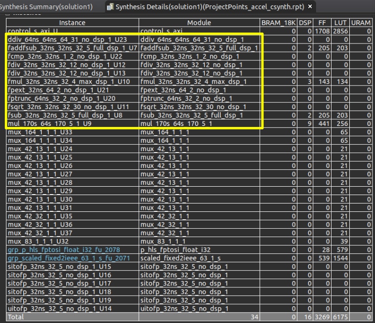
6. Integrated Logic Analyzers (ILA) cores are your friend. Unfortunately I ultimately had to remove them from my design due to resource limitations, and I forgot to snap some photos before I did, but they were an incredibly useful tool nonetheless. When I was debugging my CF accelerator, I could see that the initiation interval of three was being achieved, so I knew my pipeline directive was working.
Task #4: Run the MIPI CSI-2 RX Subsystem Example Design for the SP701.
I made a brief mention of this in the last blog. Over all I was super happy with the Xilinx example design. It was easy to get the SP701 out of the box and running to snap this photo. In the photo you can see that the camera is extremely dim, despite having excellent lighting in the room (windows are open with sunlight beaming in). I'm leaving this as a reference because I made some improvements to the image quality by using Xilinx's gamma LUT.

Task #5: Modify the example design.
Looking at the block design, it is pretty obvious that there are a lot of features that could be removed, but it's not always easy to tell how easy it is to remove. For the most part, I played it on the safe side, and left anything that I wasn't 100% certain would be fine. Here is a screenshot of the original block diagram. Blocks that are highlighted are blocks that I ultimately decided to remove. This includes a couple of AXI GPIOs, an AXI4-Stream switch, an AXI4-Stream register slice, a video processing subsystem scalar, a MIPI DSI TX Subsystem, and an AXI IIC module. Update: I also ended up removing the video test pattern generator at a later date because of resource constaints (it's the unhighlighted block directly up and to the right of the AXI4-Stream switch).
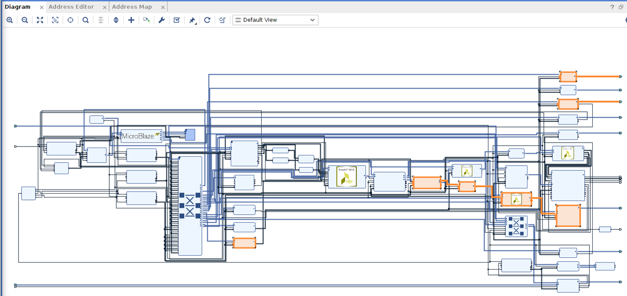
The reference design supports two ways of transmitting video, either through HDMI or MIPI DSI. Before I knew about the reference design, I was almost leaning towards using ethernet, but the reference design made it an easy decision. I decided to go with HDMI, since I had a cable and monitor on hand for it. For anyone that wants to splurge though, you can purchase a DSI compatible display, B101UAN01.7_H/W 1A. A quick google search shows that there appears to be some available on EBAY, though on short supply. This was out of my budget, so I did not buy one.
My final block design looks like the following. You can see my three accelerators. The MN and PP accelerators are the two blocks on the left beside the big AXI Interconnect. These are merely s_axilite controlled accelerators. The middle two blocks are the gamma LUT IP provided by Xilinx and the CF accelerator which uses the AXI3-Stream interface in addition to the s_axilite interface. Finally, on the far right, there is an AXI QUAD-SPI IP in the standard single bus 8-bit width configuration.
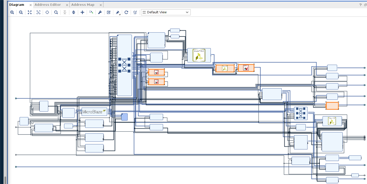
Since the SPI bus is probably the trickiest to connect, I will go into a little more detail on its setup. Double clicking the IP, you will see that it is configured as follows:
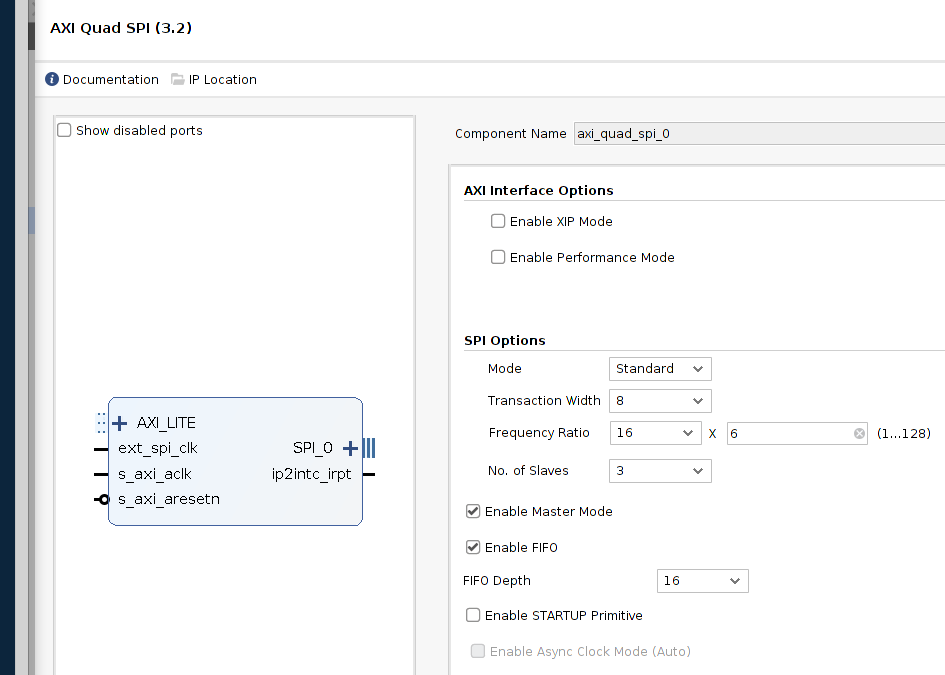
The ext_spi_clk and s_axi_aclk signals are connected to a 100MHz clock from the clock wizard. Since the frequency ratio is 16*6, the actual SPI SCLK signal wil be ~1.041MHz. SPI can support higher speeds, but I wanted to play it safe so that I could make the cable length longer if I needed to or the LSM9DS1 was out of specification. The last step is to constrain the I/O pins.
set_property PACKAGE_PIN C13 [get_ports {SPI_0_ss_io[0]}]
set_property PACKAGE_PIN A14 [get_ports {SPI_0_ss_io[1]}]
set_property PACKAGE_PIN A15 [get_ports {SPI_0_ss_io[2]}]
set_property IOSTANDARD LVCMOS33 [get_ports {SPI_0_ss_io[0]}]
set_property IOSTANDARD LVCMOS33 [get_ports {SPI_0_ss_io[1]}]
set_property IOSTANDARD LVCMOS33 [get_ports {SPI_0_ss_io[2]}]
set_property IOSTANDARD LVCMOS33 [get_ports SPI_0_io0_io]
set_property IOSTANDARD LVCMOS33 [get_ports SPI_0_io1_io]
set_property IOSTANDARD LVCMOS33 [get_ports SPI_0_sck_io]
set_property PACKAGE_PIN D14 [get_ports SPI_0_io0_io]
set_property PACKAGE_PIN B14 [get_ports SPI_0_io1_io]
set_property PACKAGE_PIN B15 [get_ports SPI_0_sck_io]
I had a build fail right afterwards because an I2C port was configured for IOSTANDARD LVCMOS25 within the same bank. This caught me by surprise, since the bank is almost entirely PMOD connectors which typically require 3.3V. This made me a little worried that there could be an electrical incompatibility. Upon closer inspection of the SP701 schematic though, the I2C lines are being regulated at 3.3V so it is safe to raise the voltage across the entire bank.
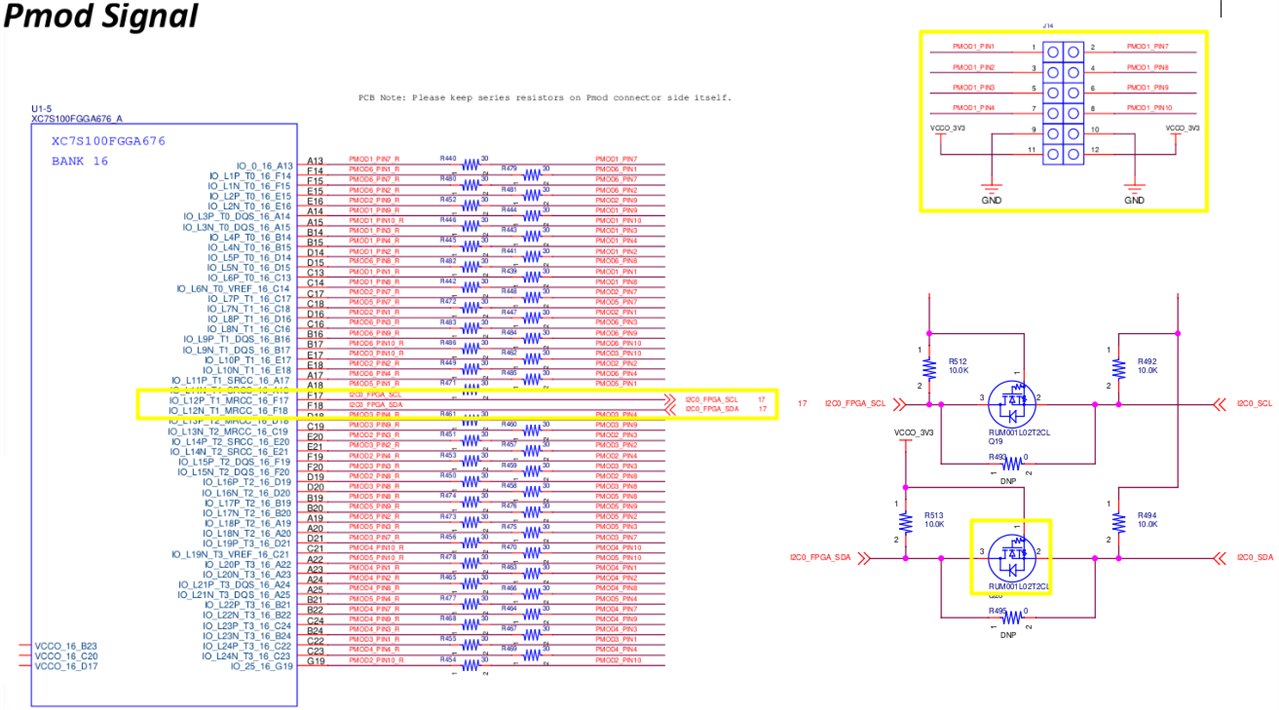
Be sure to fix the MIPI CSI I2C constraints if you use a 3.3V PMOD like the PMOD NAV:
#csi-iic0
set_property PACKAGE_PIN F17 [get_ports IIC_expander_scl_io]
#set_property IOSTANDARD LVCMOS25 [get_ports IIC_expander_scl_io]
set_property IOSTANDARD LVCMOS33 [get_ports IIC_expander_scl_io]
set_property PULLUP true [get_ports IIC_expander_scl_io]
set_property PACKAGE_PIN F18 [get_ports IIC_expander_sda_io]
#set_property IOSTANDARD LVCMOS25 [get_ports IIC_expander_sda_io]
set_property IOSTANDARD LVCMOS33 [get_ports IIC_expander_sda_io]
set_property PULLUP true [get_ports IIC_expander_sda_io]
Task #6: Integration
Most of the integration step is handled in Vitis and is pretty straightforward. To get the gamma LUT operating, I used Xilinx's gamma coefficient table. You initialize it as follows:
#include "xv_gamma_lut.h"
#include "xilinx-gamma-coeff.h"

int gamma_lut_init() {
    static XV_gamma_lut gamma_lut;
    XV_gamma_lut_Initialize(&gamma_lut, XPAR_XV_GAMMA_LUT_0_DEVICE_ID);
	XV_gamma_lut_Config *gamma_lut_config = XV_gamma_lut_LookupConfig(XPAR_XV_GAMMA_LUT_0_DEVICE_ID);
	XV_gamma_lut_CfgInitialize(&gamma_lut, gamma_lut_config, gamma_lut_config->BaseAddress);
	XV_gamma_lut_Set_HwReg_width(&gamma_lut, 1920);
	XV_gamma_lut_Set_HwReg_height(&gamma_lut, 1080);
    XV_gamma_lut_Set_HwReg_video_format(&gamma_lut, 0); // RGB = 0 (YUV = 1)
    u16 gamma_r = 4;
    u16 gamma_g = 5;
    u16 gamma_b = 5;
    XV_gamma_lut_Write_HwReg_gamma_lut_0_Words(&gamma_lut, 0, (int *) xgamma8_curves[gamma_r], sizeof(xgamma8_10)/sizeof(int));
	XV_gamma_lut_Write_HwReg_gamma_lut_1_Words(&gamma_lut, 0, (int *) xgamma8_curves[gamma_g], sizeof(xgamma8_10)/sizeof(int)));
	XV_gamma_lut_Write_HwReg_gamma_lut_2_Words(&gamma_lut, 0, (int *) xgamma8_curves[gamma_b], sizeof(xgamma8_10)/sizeof(int)));
	XV_gamma_lut_EnableAutoRestart(&gamma_lut);
	XV_gamma_lut_Start(&gamma_lut);

	return XST_SUCCESS;
}
You also need to intialize the LSM6DS1 SPI library provided by Digilent.
#include "PmodNAV.h"
PmodNAV nav;

//////////////////////////////////////////////////

	// Initialize IMU
	NAV_begin (&nav, -1, XPAR_SPI_0_BASEADDR);// initialize the PmodNAV driver device
	NAV_Init(&nav); // initialize the connection with each spi slave
	float accelerometer_only_odr, accelerometer_gyroscope_odr, magnetometer_odr, altimeter_odr;
//	NAV_SetODR(&nav, NAV_ACL_MODE_INST_A, NAV_ACL_ODR_XL_476HZ);
//	NAV_SetODR(&nav, NAV_ACL_GYRO_MODE_INST_AG, NAV_GYRO_ODR_G_476HZ);
//	NAV_SetODR(&nav, NAV_MAG_MODE_INST_MAG, NAV_MAG_ODR_M_80HZ);
//	NAV_SetODR(&nav, NAV_ALT_MODE_INST_ALT, NAV_ALT_ODR_ALT_25HZ);
	accelerometer_only_odr = NAV_GetODR(&nav, NAV_ACL_MODE_INST_A);
	accelerometer_gyroscope_odr = NAV_GetODR(&nav, NAV_ACL_GYRO_MODE_INST_AG);
	magnetometer_odr = NAV_GetODR(&nav, NAV_MAG_MODE_INST_MAG);
	altimeter_odr = NAV_GetODR(&nav, NAV_ALT_MODE_INST_ALT);
	xil_printf("accelerometer_only_odr=%d\r\n", (u16) accelerometer_only_odr);
	xil_printf("accelerometer_gyroscope_odr=%d\r\n", (u16) accelerometer_gyroscope_odr);
	xil_printf("magnetometer_odr=%d\r\n", (u16) magnetometer_odr);
	xil_printf("altimeter_odr=%d\r\n", (u16) altimeter_odr);
The accelerators use a very similar initialization model as well.
#include "xmadgwicknav_accel.h"
#include "xmadgwicknav_accel_hw.h"
#include "xprojectpoints_accel.h"
#include "xprojectpoints_accel_hw.h"
#include "xcoordinateframe_accel.h"
#include "xcoordinateframe_accel_hw.h"

//////////////////////////////////////////////////

	float g_range = NAV_GetXLRangeLSB(NAV_ACL_PAR_XL_2G);//NAV_GetRangeXL(&nav);
	float dps_range = NAV_GetGRangeLSB(NAV_GYRO_PAR_G_245DPS);//NAV_GetRangeG(&nav);
	float gauss_range = NAV_GetMAGRangeLSB(NAV_MAG_PAR_MAG_4GAUSS);//NAV_GetRangeMAG(&nav);
	float beta = 0.1f;//0.033f;//0.1f;
	float q0 = 1.0f;
	float q1 = 0.0f;
	float q2 = 0.0f;
	float q3 = 0.0f;
	float invSampleFreq = 1.0f / 50.0f;
	float invSampleFreqIteratively = invSampleFreq / 1.0f;

	float rx, ry, rz;
	int x0, y0, fx, fy, tz, r;
	rx = -0.3;
	ry = 2.4;
	rz = -0.7;
	x0 = 960;
	y0 = 540;
	fx = 1000;
	fy = 1000;
	tz = 5;
	r = 10;

    // MN accelerator
	XMadgwicknav_accel mn;
	XMadgwicknav_accel_Initialize(&mn, XPAR_MADGWICKNAV_ACCEL_0_DEVICE_ID);
	XMadgwicknav_accel_Config* mn_config = XMadgwicknav_accel_LookupConfig(XPAR_MADGWICKNAV_ACCEL_0_DEVICE_ID);
	XMadgwicknav_accel_CfgInitialize(&mn, mn_config);
	XMadgwicknav_accel_Set_g_range(&mn, *((u32*)&g_range));
	XMadgwicknav_accel_Set_dps_range(&mn, *((u32*)&dps_range));
	XMadgwicknav_accel_Set_gauss_range(&mn, *((u32*)&gauss_range));
	XMadgwicknav_accel_Set_beta(&mn, *((u32*)&beta));
	XMadgwicknav_accel_Set_q0_i(&mn, *((u32*)&q0));
	XMadgwicknav_accel_Set_q1_i(&mn, *((u32*)&q1));
	XMadgwicknav_accel_Set_q2_i(&mn, *((u32*)&q2));
	XMadgwicknav_accel_Set_q3_i(&mn, *((u32*)&q3));
	XMadgwicknav_accel_Set_invSampleFreq(&mn, *((u32*)&invSampleFreq));

    // PP accelerator
	XProjectpoints_accel pp;
	XProjectpoints_accel_Initialize(&pp, XPAR_PROJECTPOINTS_ACCEL_0_DEVICE_ID);
	XProjectpoints_accel_Config* pp_config = XProjectpoints_accel_LookupConfig(XPAR_PROJECTPOINTS_ACCEL_0_DEVICE_ID);
	XProjectpoints_accel_CfgInitialize(&pp, pp_config);
	XProjectpoints_accel_Set_rx(&pp, *((u32*) &rx));
	XProjectpoints_accel_Set_ry(&pp, *((u32*) &ry));
	XProjectpoints_accel_Set_rz(&pp, *((u32*) &rz));
	XProjectpoints_accel_Set_x0(&pp, x0);
	XProjectpoints_accel_Set_y0(&pp, y0);
	XProjectpoints_accel_Set_fx(&pp, fx);
	XProjectpoints_accel_Set_fy(&pp, fy);
	XProjectpoints_accel_Set_tz(&pp, tz);
	XProjectpoints_accel_Set_r(&pp, r);
	XProjectpoints_accel_Start(&pp);
	while (!XProjectpoints_accel_IsDone(&pp));

    // CF accelerator
	XCoordinateframe_accel cf;
	XCoordinateframe_accel_Initialize(&cf, XPAR_COORDINATEFRAME_ACCEL_0_DEVICE_ID);
	XCoordinateframe_accel_Config* cf_config = XCoordinateframe_accel_LookupConfig(XPAR_COORDINATEFRAME_ACCEL_0_DEVICE_ID);
	XCoordinateframe_accel_CfgInitialize(&cf, cf_config);
	XCoordinateframe_accel_Set_rows(&cf, 1080);
	XCoordinateframe_accel_Set_cols(&cf, 1920);
	XCoordinateframe_accel_Set_r(&cf,r);
	XCoordinateframe_accel_Set_r_en(&cf,TRUE);
	XCoordinateframe_accel_Set_c_en(&cf,TRUE);
	XCoordinateframe_accel_EnableAutoRestart(&cf);
	XCoordinateframe_accel_Start(&cf);
Then you need to set up the main loop which processes data in order: IMU -> MN -> PP -> CF. I've also added a neat macro which allows you to pass data from the PP accelerator to the CF accelerator more susinctly.
#define PP_GET_CF_SET(reg) XCoordinateframe_accel_Set_ ## reg(cf, XProjectpoints_accel_Get_ ## reg(pp));
void pp_get_cf_set(XProjectpoints_accel *pp, XCoordinateframe_accel *cf)
{
	PP_GET_CF_SET(z_fg0);
	PP_GET_CF_SET(z_fg1);
	PP_GET_CF_SET(z_fg2);
	PP_GET_CF_SET(ip0_x);
	PP_GET_CF_SET(ip0_y);
	PP_GET_CF_SET(ip1_x);
	PP_GET_CF_SET(ip1_y);
	PP_GET_CF_SET(ip2_x);
	PP_GET_CF_SET(ip2_y);
	PP_GET_CF_SET(ip3_x);
	PP_GET_CF_SET(ip3_y);
	PP_GET_CF_SET(x_axis_rectangle_p0_x);
	PP_GET_CF_SET(x_axis_rectangle_p0_y);
	PP_GET_CF_SET(x_axis_rectangle_p1_x);
	PP_GET_CF_SET(x_axis_rectangle_p1_y);
	PP_GET_CF_SET(x_axis_rectangle_p2_x);
	PP_GET_CF_SET(x_axis_rectangle_p2_y);
	PP_GET_CF_SET(x_axis_rectangle_p3_x);
	PP_GET_CF_SET(x_axis_rectangle_p3_y);
	PP_GET_CF_SET(y_axis_rectangle_p0_x);
	PP_GET_CF_SET(y_axis_rectangle_p0_y);
	PP_GET_CF_SET(y_axis_rectangle_p1_x);
	PP_GET_CF_SET(y_axis_rectangle_p1_y);
	PP_GET_CF_SET(y_axis_rectangle_p2_x);
	PP_GET_CF_SET(y_axis_rectangle_p2_y);
	PP_GET_CF_SET(y_axis_rectangle_p3_x);
	PP_GET_CF_SET(y_axis_rectangle_p3_y);
	PP_GET_CF_SET(z_axis_rectangle_p0_x);
	PP_GET_CF_SET(z_axis_rectangle_p0_y);
	PP_GET_CF_SET(z_axis_rectangle_p1_x);
	PP_GET_CF_SET(z_axis_rectangle_p1_y);
	PP_GET_CF_SET(z_axis_rectangle_p2_x);
	PP_GET_CF_SET(z_axis_rectangle_p2_y);
	PP_GET_CF_SET(z_axis_rectangle_p3_x);
	PP_GET_CF_SET(z_axis_rectangle_p3_y);
}

/////////////////////////////////////////////////////


	u32 uq0, uq1, uq2, uq3;
	uq0 = XMadgwicknav_accel_Get_q0_i(&mn);
	uq1 = XMadgwicknav_accel_Get_q1_i(&mn);
	uq2 = XMadgwicknav_accel_Get_q2_i(&mn);
	uq3 = XMadgwicknav_accel_Get_q3_i(&mn);
	while (1)
	{
		XTmrCtr_Start(&TmrCtrInst, TMRCTR_DEVICE_ID);


		int16_t AclX, AclY, AclZ;
		AclX = 0;
		AclY = 0;
		AclZ = 0;
		NAV_ReadAccel(&nav, &AclX, &AclY, &AclZ);

		s16 GX, GY, GZ;
		NAV_ReadGyro(&nav, &GX, &GY, &GZ);

		s16 MagX, MagY, MagZ;
		NAV_ReadMag(&nav, &MagX, &MagY, &MagZ);


		XMadgwicknav_accel_Set_aix(&mn, AclX);
		XMadgwicknav_accel_Set_aiy(&mn, AclY);
		XMadgwicknav_accel_Set_aiz(&mn, AclZ);
		XMadgwicknav_accel_Set_gix(&mn, GX);
		XMadgwicknav_accel_Set_giy(&mn, GY);
		XMadgwicknav_accel_Set_giz(&mn, GZ);
		XMadgwicknav_accel_Set_mix(&mn, 0);//MagX);
		XMadgwicknav_accel_Set_miy(&mn, 0);//MagY);
		XMadgwicknav_accel_Set_miz(&mn, 0);//MagZ);
		XMadgwicknav_accel_Set_q0_i(&mn, uq0);
		XMadgwicknav_accel_Set_q1_i(&mn, uq1);
		XMadgwicknav_accel_Set_q2_i(&mn, uq2);
		XMadgwicknav_accel_Set_q3_i(&mn, uq3);

		XMadgwicknav_accel_Start(&mn);
		while (!XMadgwicknav_accel_IsDone(&mn));

		u32 uroll_rad = XMadgwicknav_accel_Get_roll_rad(&mn);
		u32 upitch_rad = XMadgwicknav_accel_Get_pitch_rad(&mn);
		u32 uheading_rad = XMadgwicknav_accel_Get_heading_rad(&mn);
		float roll_rad = *((float*)&uroll_rad);
		float pitch_rad = -*((float*)&upitch_rad);
		float heading_rad = -*((float*)&uheading_rad);

		uq0 = XMadgwicknav_accel_Get_q0_o(&mn);
		uq1 = XMadgwicknav_accel_Get_q1_o(&mn);
		uq2 = XMadgwicknav_accel_Get_q2_o(&mn);
		uq3 = XMadgwicknav_accel_Get_q3_o(&mn);


		XProjectpoints_accel_Set_rx(&pp, *((u32*) &roll_rad));
		XProjectpoints_accel_Set_rz(&pp, *((u32*) &pitch_rad));
		//XProjectpoints_accel_Set_ry(&pp, *((u32*) &heading_rad));
		float zero = 0;
		XProjectpoints_accel_Set_ry(&pp, *((u32*) &zero));
		XProjectpoints_accel_Start(&pp);
		while (!XProjectpoints_accel_IsDone(&pp));

		pp_get_cf_set(&pp, &cf);

		while (not_elasped(&TmrCtrInst, TMRCTR_DEVICE_ID, invSampleFreqIteratively));//invSampleFreq));
		XTmrCtr_Stop(&TmrCtrInst, TMRCTR_DEVICE_ID);
		//print_elasped_time(&TmrCtrInst, TMRCTR_DEVICE_ID);

	}
Final Utilization
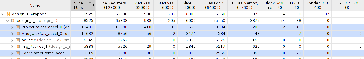
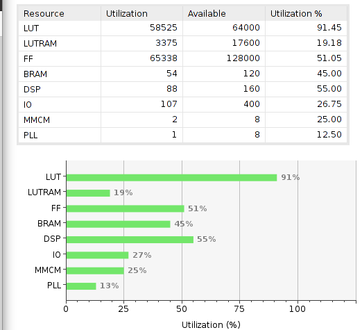
Conclusion
Overall, I'm pretty satisfied with how things turned out. There is definitely a lot of area for improvement, but I think the result turned out okay.
There are a few limitations that I have to acknowledge. (1) The Madgwick filter for the IMU uses arctan and arcsin which return values in the range of −π/2 to π/2. I don't have a way to track the full −π to π range. (2) I did not calibrate the IMU which is terrible thing to do if you want good results, right now the magnetometer data is effectively useless or even counteractive to the final result. (3) The resource utilization is much higher than what it should be. I should be able to get a lot more out of the FPGA in the same amount of space. (4) Due to a typo that identified earlier in this blog post, one of the axis rectangles looks sliced diagonally.
Video Demo
This demo walks through a few features to show the capabilities of the Project Points and Coordinate Frame accelerators. Once this is done, it enters IMU mode and the Madgwick filter sends the data to the rest of the pipeline in real time.


