


Introduction
This project is essentially a continuation, or more precisely complete rework and re-imagining of my earlier project in the Eye on Intelligence Challenge. In this blog, I will recap the goals, systems, and ideas from that project, and plan the new system that will take its place.
The original idea was to make a DIY dashcam. The initial version used a Raspberry Pi 4 and a Raspberry Pi HQ camera to do this. I realized early on that adding a 4G modem and batteries to the system would make it way more versatile and useful.
The main goal is to stream the camera feed in real-time to a remote server, even when the car is parked. This immediately resolves two of the biggest problems with regular dashcams:
- If an accident happens, a regular dashcam only stores video locally, and the storage media may get destroyed in the accident.
- If the vehicle or dashcam gets stolen, the storage media gets stolen along with it.
Not relying on local storage at all fixes these two issues, but brings a mountain of challenges with it. To mention just a few:
- Stream latency is critical: an accident can happen in less than a second in the worst cases. Imagine an oncoming car experiencing a tire blowout just meters in front, and colliding with our vehicle, destroying the dashcam. If the video stream was not encoded and transmitted within less than a second, zero footage of the accident will have been recorded.
- Handling network connection dropouts: It is almost certain that the network connection’s quality will degrade or completely drop out at certain times. This makes the previous latency goal impossible to achieve in certain scenarios, and very difficult in others.
- WWAN hardware consumes a lot of power. Running it for an extended period of time requires a massive battery.
Summary of my earlier project
The system was composed of the following major components:
- Raspberry Pi 4
- Raspberry Pi HQ Camera
- Digilent Arty Z7 (Zynq 7020) FPGA for NN inference acceleration
- Sierra Wireless EM7455 4G Modem
- 12V 40Ah (8x 12V 5Ah) AGM battery bank, 4x BQ25756 buck-boost chargers
- MCP2515 CAN transceiver to interface with the vehicle's CAN network
The AGM battery bank had two ways of charging:
- With the engine running, the vehicle’s generator provided power to the four chargers
- When parked, solar panels could be connected, and the BQ25798 charger ICs would do MPPT to charge the battery bank.
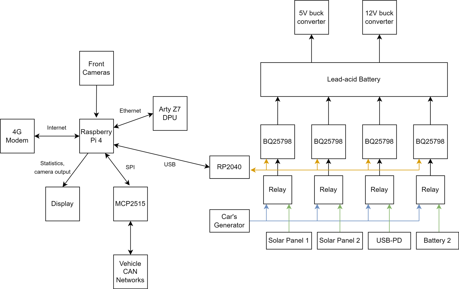
The Raspberry Pi 4 used its hardware H264 encoder to create a constant bitrate, 6Mbps video stream, that was sent over an OpenVPN connection to my remote server.
All sorts of metrics, along with GPS data, was logged to an InfluxDB server running on the Pi, set up to replicate data to the remote server as well. A Grafana dashboard provided easy access and nice visualizations for this.
Issues and Improvements
There were two major issues present in this implementation, but almost all parts were suboptimal in some way.
Video Streaming
The image quality, encoder efficiency, and streaming setup in general was ill-suited to this project, due to the constant bitrate (CBR) output of the Pi 4’s hardware H264 block: the encoder is given a target bitrate (bitrate here essentially refers to the ‘video size’ produced) to precisely maintain, no matter what.
This is very obviously problematic: in low complexity scenarios, like when parked, close to zero movement is happening on the video. Very little bitrate is required to produce a sufficient quality video stream (about 2Mbps roughly, in my testing).
In complex, fast movement scenarios, like when driving fast in a dense city, almost everything is always changing, and a lot higher bitrate is required to maintain the same quality (10+ Mbps).
The solution to this problem is the variable bitrate (VBR) mode. Instead of specifying a bitrate to maintain, the encoder is told what ‘visual quality’ to maintain, and it dynamically adjusts its own bitrate to keep that video quality.
The Raspberry Pi 4’s hardware encoder does not support this mode (or at least not to the extent I need it), so my crude workaround in the previous project was to lower the CBR target bitrate to 1Mbps when the engine was not running.
Hardware encoders in general tend to struggle with VBR, so addressing this issue will be one of the biggest challenges in this project.
The overall goal is to minimize bitrate to the bare minimum at all times, while maintaining a decent video quality: this minimizes the video streaming latency and lets the system function well, even with a mediocre 4G connection.
The camera’s image quality was subpar too: the IMX477 in the Pi HQ Camera is not very good in low light scenarios, and also has relatively bad dynamic range. This meant that nighttime parked footage was close to useless, as the image was pretty much completely black, nighttime driving footage was horrible due to street lights and headlights blinding the camera, and direct sunlight into the sensor also destroyed image quality in the daytime.
The MIPI link from the camera to the Pi also interfered with GPS, the whole camera was massive, and the lens FOV was terrible.
Battery and Charging
The AGM battery bank’s capacity, around 40Ah on paper, turned out to be wildly undersized. It provided enough energy for roughly 2 days of parked time. Constant cycling and deep discharging are also horrible for these batteries, so the already low capacity just kept decreasing over time.
The charger system was also suboptimal: I used 4 separate “5A” charger ICs in parallel, but the absolute maximum input current they can do is 3.3A, translating to roughly around 10A maximum charging current for the entire charger setup. This was too little to keep the batteries charged purely by the engine, when driving.
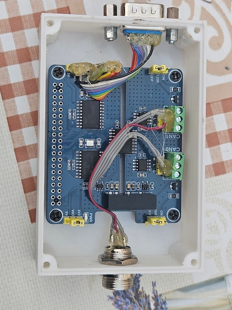
The wiring and general ‘aesthetics’ of the system were horrible too:
The CAN bus controllers and transceivers, along with the 4G modem, were also located in separate, external 'boxes', with cables attaching them to the main unit. The FPGA was just thrown in there too, with an Ethernet link to the Raspberry Pi.

Post 'Eye on Intelligence Challenge' improvements
I ended up really liking the overall concept of having an always on, real-time streaming dashcam, and improving it has been on my mind for quite some time. This SPE challenge is the perfect opportunity to do so, but the original setup was way too messy for my liking, so I made some changes soon after the end of the previous challenge, to make it actually decent, and not a fire hazard in the meantime.
Tackling the H264 constant bitrate problem was first, I solved the issue by upgrading to a Raspberry Pi 5, and doing software H264 encoding, which fully supports variable bitrate.
To fix up the wiring mess, I decided to get rid of 2 of the charger modules, and the FPGA. Halving the number of chargers might seem odd, considering that 4 of them wasn’t sufficient in the first place. The rationale was that I had to carry a second battery almost every day to swap with and charge at home anyways, and only having 2 chargers significantly simplifies the circuit, so the net result would be an improvement.
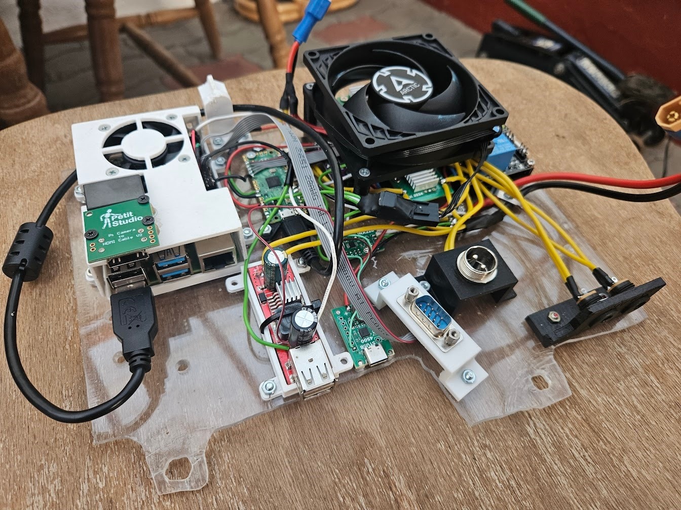
I also changed the Pi Pico for an ESP32, added a few TPS566231 buck converters, and properly soldered together a PCB to hold everything.
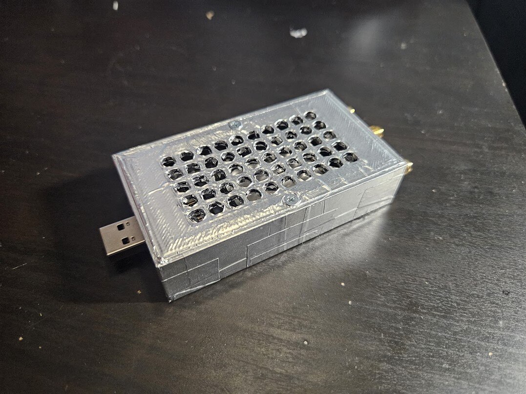
The end result is a much nicer contraption:
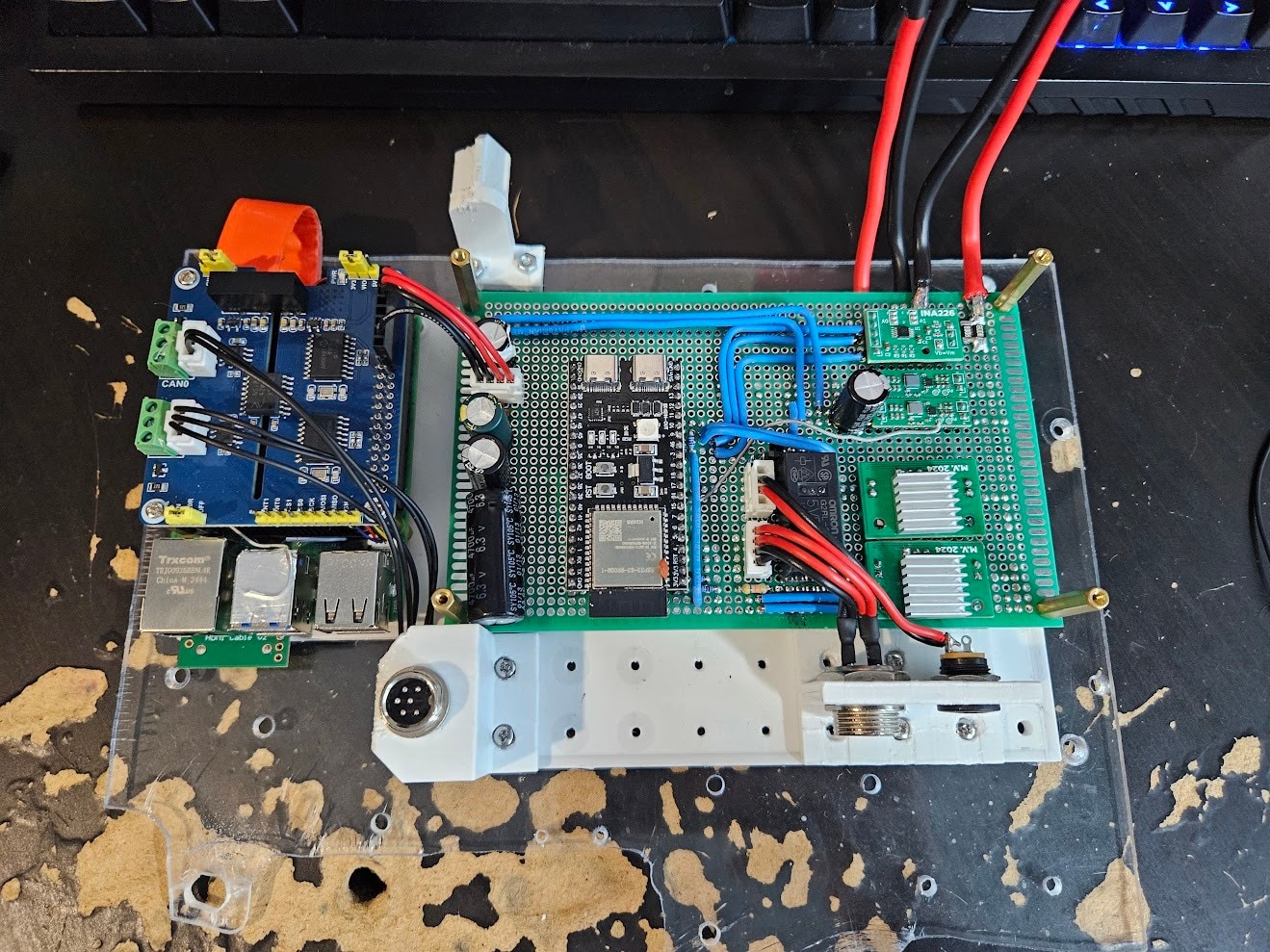

The CAN bus hat is now used as an actual HAT, and not in a separate box (don't ask me why I didn't do it this way the first time, I have absolutely no idea). However, the 4G modem remains as a dongle on a USB cable.
Plans for the next version
The revision shown above has proven to be reliable and actually useful, so let’s see what could be improved during this challenge.
Battery and Charging
By far the biggest problem is battery life and charging power. AGM batteries are not fit for this purpose, and we need a way beefier charger.
The battery life target for the new version is 3-4 days, and the charger should be powerful enough to never have to manually swap/charge batteries.
Doing some quick math with rough approximations, we arrive at this:
- The system is expected to use around 10W of power.
- 3-4 days of battery life would thus require a 720-960Wh battery (assuming 100% depth of discharge, which is not a great idea). To give us some headroom, 1kWh would be a reasonable target.
- In the time period I counted, I found that I drive my car for roughly 30 hours a month. This comes out to exactly 1 hour per day on average.
- To replenish one day worth of power in one hour of driving, we’d need to charge at 240W, or roughly 20A input current to the charger, from the vehicle.
Putting a 20A charger on the same PCB as sensitive, low power electronics, would be an unwise idea. Therefore, I made the decision to create a separate ‘power management’ PCB, that will contain the charger, power monitoring and fuel gauging, protection, etc. components, along with a microcontroller, and mount them on the battery.
This would make the battery a self-contained, ‘autonomous’ system, handling its own charging and monitoring.
The Linux system running the show still needs to have some level of control and detailed statistics about the battery though. This is where Single Pair Ethernet comes in.
For such applications, there are a few important features needed in the communication link:
- Isolation – while the entire setup will be sharing a common ground, it is still a good idea to have an isolated interface. Stray currents in sensitive, low noise data connections can mess things up and cause headaches. Pulling significant amps would also result in a ground offset, potentially destroying the signal. Isolation is technically overkill, but it is cheap insurance to make sure everything works perfectly.
- Resiliency – the cable run between the Linux system and the power management module could be as long as 4 meters depending on where I end up positioning things, and the cables will be running alongside super noisy, high current wires. It is crucial that the link is robust, tolerates noise, and supports (relatively) long cable runs.
- Simplicity – running gigabit ethernet over a fiber link would certainly meet both of the requirements above, but it’s not exactly simple, cheap, or designed for this purpose.
There are 3 reasonable options in my opinion, that fit the bill:
- RS485: a full-duplex RS485 link would need two twisted pairs, and could be hooked up to a regular UART interface on a microcontroller. This option can essentially be thought of as making a regular UART/Serial interface reliable for long ranges and high noise.
- CAN bus: ubiquitous for exactly this sort of application. Requires only a single pair, fixes the downsides mentioned for RS485. The protocol itself is higher level, instead of sending individual bits, data is sent in messages, with a priority system, error detection, automatic retransmission, etc.
- Single Pair Ethernet: even more advanced and faster than CAN bus. Still requires a single pair only, and can be used with an entire Ethernet stack. That means things like IP addressing, QoS, VLANs, flow control, etc.
Initially, I would have opted for CAN bus, if not for this Single Pair Ethernet challenge. I did not pay much attention to SPE, as CAN bus was familiar and good enough for my past projects. However, I looked into SPE, and found that it has essentially no downsides, but lots of upsides for my project:
- Way more bandwidth available: 10x faster than classic CAN.
- Competitive price: while a regular, non-isolated CAN PHY is cheaper, once isolation is required, a Single Pair Ethernet PHY and magnetics end up being roughly in the same price range as an isolated CAN transceiver and controller.
- Much more features and options for high level protocols.
One disadvantage that could be a dealbreaker in some use cases: SPE (or, to be more precise, 10BASE-T1L, the version we will be using) is NOT a multi-drop bus. This means that a single physical bus can only connect two devices together, much like ‘regular’ Ethernet, and a switch is required to connect more than 2 devices together.
However, there is another SPE standard, 10BASE-T1S, which solves this exact problem, making SPE work just like CAN bus in this regard: multiple devices can be connected to a single, one pair bus, without any switches or other active devices.
This challenge is about 10BASE-T1L though, which is perfectly adequate for this project.
Application Processor
The Raspberry Pi 5 works fairly well, but it’s somewhat underpowered, and also lacks a hardware video encoder, which would significantly reduce power consumption and CPU usage.
Many modern SoCs integrate a proper H264, or even H265 encoder block, that would be incredibly useful here.
Some modern GPUs contain AV1 encoders too, which would be even better than H265, but these are usually large PCIe cards, meant for desktop computers.
Power consumption is by far the biggest constraint, the entire ‘processing system’, running Linux, encoding video, along with a dozen other services, has to stay under ideally 5W.
Choosing the best possible option for our constraints will be crucial for achieving the best possible battery life and video quality.
Cameras
As mentioned earlier, the Raspberry Pi HQ Camera is not well suited to this project. Its low light performance and dynamic range are simply not sufficient. The MIPI interface is also a pain to deal with in my case.
Another issue is that the Raspberry Pi 5, and most other single board computers, only support 2 or maybe 3 MIPI interfaces at most, and I have plans to use 4+ cameras.
By far the simplest and most common interface to use would be USB, which deals reasonably well with noise and interference, supports long enough cable runs, and is trivial to get enough ports on a single board computer or any other device.
Picking the perfect camera module is a challenging task, that I will go into more detail about in a future blog post.
Planned Posts
In the upcoming posts, I will go into detail about all of the identified improvement opportunities and issues present with the current setup, and talk about picking the best way forward, obtaining parts, and building the components of the new system.
The rough plan is the following:
- Part 2: Battery and Charging System
- Part 3: The new ‘Compute Unit’ – the box with the SoC, modem, etc.
- Part 4: Cameras and Sensors
- Part 5: Single Pair Ethernet hardware, software
- Final Summary Blog – showcase of the finished system and its capabilities
You might notice that most of the blogs don’t actually contain much Single Pair Ethernet related work. This is due to some unfortunate mishandling of my package containing the SPE hardware, which I still have not received, but should be arriving next week.
Waiting with the project until the arrival of the package would have certainly made it impossible to finish within the timeframe of this challenge, so I had to work on most parts without having the Single Pair Ethernet hardware in hand.
To be specific, the ‘Battery and Charging System’ (Part 2), and ‘The new Compute Unit’ (Part 3) hardware were mostly completed before any of the SPE hardware arrived, with placeholder electronics and careful preplanning. Blog 5 will be about actually adding Single Pair Ethernet to these units.
Also, massive thanks to E14Alice for helping with getting the package situation sorted out.

