Hello everyone. I welcome you to my next blog as part of Experimenting with Supercapacitors. The last blog before I post my final blog I want to use for description of some details about my next experiment: self-discharge evaluation. My remaining experiment which I did not describe yet is testing different supercapacitors with my Mini Solar Powered Wireless Temperature Sensor. This experiment I will describe in detail in my final blog. These two experiments are the most time intensive because their measurement take one or more days. For this reason, I publish them at the end of design challenge period, but I actually started doing them much sooner (for example, experiment from previous blog I started later than these two).
Self-Discharge
Self-discharge is effect when unloaded capacitor discharges itself even there is no load connected to it. If you charge capacitor and store in it in the drawer for two months, the capacitor will not be charged to the same level as it was when inserting to the drawer. Some capacitors self-discharge faster than others. Self-discharge is usually low, but there are some applications when high self-discharge can cause serious issue. For example, powering low-power RTC chips. They maintain real time clock (year, month, date, hours, minutes, seconds). RTC power consumption is very low, so if the capacitor self-discharge very fast, it will significantly reduce operation duration. With nowadays RTC chips we can achieve very low currents so total lifespan can be with reasonable large supercap several weeks, but if supercap self-discharge in 5 days, then we are out of luck. Because we received capacitors from multiple families internally based on different technologies, it is nice to evaluate their self-discharge behaviour and compare them.
Experiment
For measuring I had chosen very simple strategy. I will charge supercapacitor and then will look how fast is it discharging. I regularly measure and logs voltage which allows further analysis.
Circuit
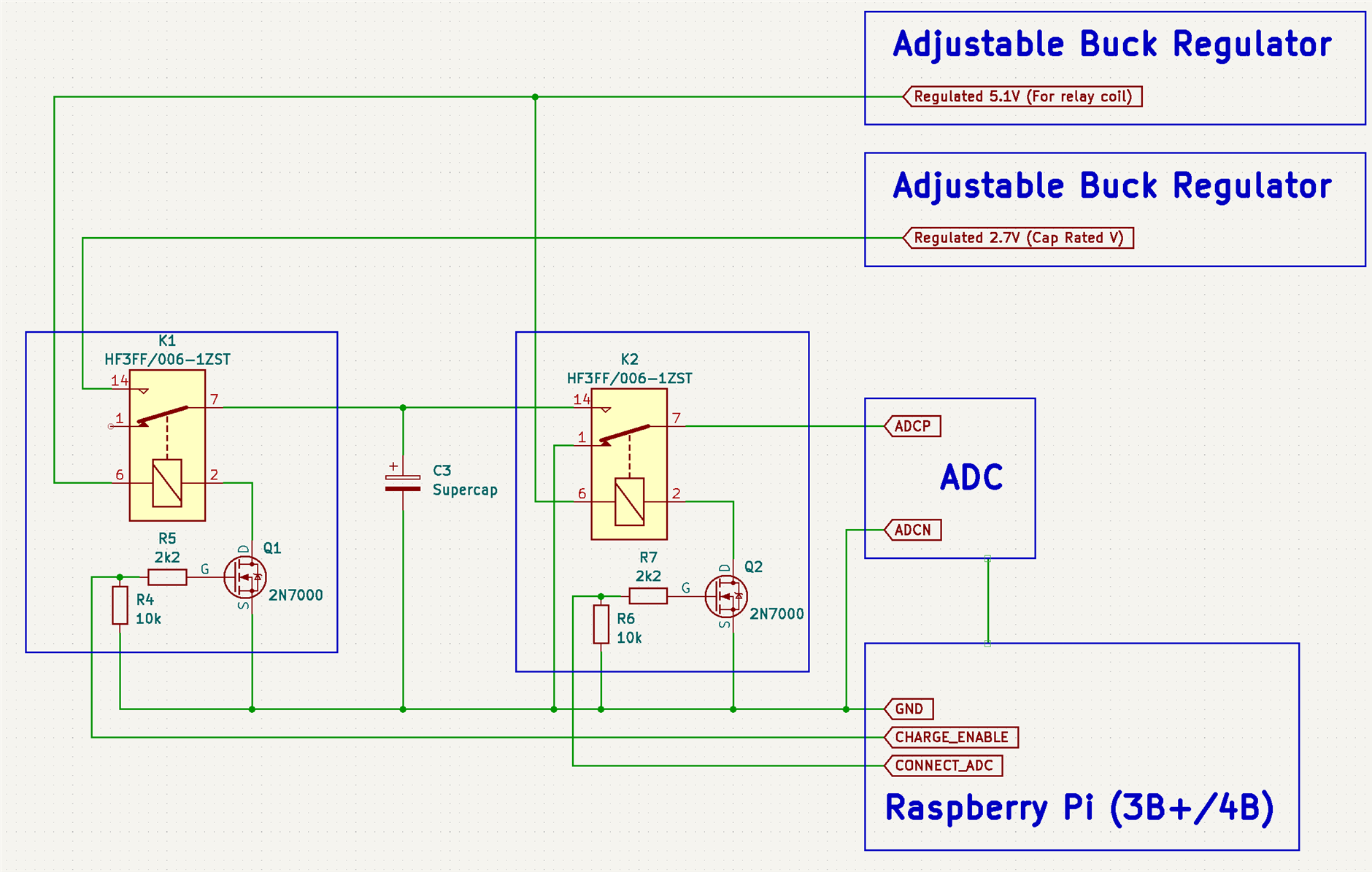
Circuit of this experiment is quite a simple. It reuses many parts which I used in previous experiments. In this experiment I use Raspberry Pi again and for selecting circuit paths I use relays. Relays has benefit that there is no leakage on transistors and other high-impedance inputs. This time they are connected that most of the time absolutely nothing is connected to the capacitor. When Raspberry Pi wants to measure capacitor voltage it needs to swich one relay first. After completing measurement is disconnects from the capacitor. The second relay is used for connecting to power supply which used for charging. ADC is MAX11410 which is exactly the same chip as I have used in experiment with measuring capacitance. Here is the full schematic:

In real world it looks as follows:

This circuit is connected and running on my desk for quite a long time. Before taking photo, I had to basically clean dust from the desk.
Measurements
For now, I have collected lot of measurements. I of course try measuring self-discharge of various capacitors and I also want to try change conditions, more precisely I especially try change charging time which will later allow me to answer questions like how much self-discharging differ when solar sensor is powered by sun at shiny day and how much its self-discharge if charging is very short time or highly limited at dark day.
I still run some measurements, so I will publish final results and some interesting notices in my final blog, but let’s look for some already collected data.
1F DGH Family Supercapacitor Self Discharge
At first, let’s look how it behave when exposed to constant voltage power supply set to slightly under capacitor rated voltage (which is 2.7V). At the beginning my script collects data more frequently and later it starts collecting samples once per 20 minutes. Let’s look how capacitor behave after it was charging from zero volts for 100 seconds. Before experiment all capacitors were discharged (shorted) for at least half hour (some for several days, some for slightly over half hour, but always it was at least half hour). 100 second period is long enough to fully charge 1F capacitor and it also decreased it’s leakage current in this time significantly. Leakage current and self-discharge are dependent.
In first half hour it looked like exponential behaviour:

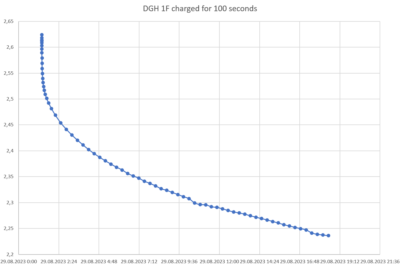
In first half hour capacitor dropped 0,14 volts which is about 5% of voltage to which the capacitor was charged. Exponential behaviour continued for some time but later changed to liner. On the following image is full plot of collected data (previous was highlighting first half an hour).

In linear part the capacitor loses about 0,009 volt per hour. It is 0,3% of voltage. In theory to 1V it decreases in about 154 hours since charged. This is not problem for my solar powered temperature sensor which needs just to survive night, but for running RTC chip this can be a serios issue. But remember that supercapacitor was charged just 100 seconds. Charging it longer will reduce the self-discharge. In case of RTC use case, the capacitor is powered almost permanently and handles only outages. I did the same experiment when the same capacitor was charged from zero volts for 1000 seconds (ten times more) and the self-discharge (in linear region) dropped to 0,005 volt per hour which means that the capacitor will from rated voltage 2.7V to 1V self-discharge in about 307 hours which is about twice than it case when it was powered just for 100 seconds (ten times less).
This is just an example of measurement which I did in recent weeks. I have now lot of more data but I still doing some tests.
Conclusion
This is all from my blog. I just completing my measurement. Running last long-term tests and write the final blog which I will post in about one week. In final blog I will also post some additional more detailed results including results and my opinions based on data form this experiment as well as all other experiments which I promised in my introduction blog. Thank you for reading this blog and enjoy rest of the day.

