Auto-Cutoff Circuit for Room Heaters - BLOG 1
This is the first blog in the Experimenting with Thermal Switches Challenge. In this blog, I'll introduce myself and the experiments that I wish to conduct using the thermal switches from Kemet.
I'm an electronics engineer with about eight years of experience in various domains such as analog, RF, and embedded systems. I frequently participate in Design Challenges on e14 Community. I wish that someday I'll have my electronics lab to perform advanced experiments with RF and play around with instruments to analyze various circuits.
Proposed Project
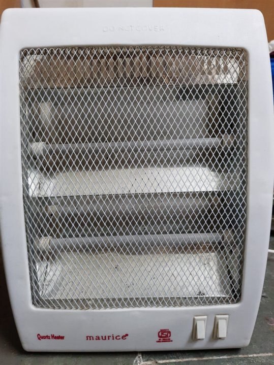
Room heaters are very common in Indian homes during winters. Since the winter weather is not as harsh in many states, people do not have thermostats and radiators for the entire house; instead, they use typical room heaters like the one shown in the picture.

These heaters are available in various models and power. This is a very basic heater with two heating elements, each 400W. Each heating element is a coiled resistance wire directly connected to the AC supply. The alternating current heats the coil according to the equation H = I2Rt, where I is the amount of current flowing in the wire, R is the resistance of the wire, and t is the amount of time the current flows.
These heaters cause suffocation and overheating of the room as there is no temperature control mechanism. These heaters are highly inefficient. But the problem with these heaters is not only their efficiency but also their safety. It comes with a simple switch at the bottom, which cuts off the power supply to the heating elements if the heater topples.
But imagine a situation on a cold wintery night, you keep the heater on and fall asleep. There have been multiple accidents and deaths due to these heaters if someone forgot to switch it off before sleeping. Hence, I plan to design a simple temperature-control circuit for such a heater using the Kemet thermal switches provided in the experiment design kit. I plan to restrict myself to using only discrete components and not go for any complex MCU as I want to keep the cost of the circuit low such that a common person can afford the circuit and easily integrate this safety feature with the heater.
Block Diagram
The basic block diagram of the heater with the thermal cutoff circuit is shown below.

The basic components for the circuit consist of the heater, a relay to control the heater using the comparator output, an opamp for comparator, and the thermal switch from the design kit.
If time permits, I'll perform more experiments with the thermal switches by using them in other projects.
I would like to thank the e14 team and Kemet for sponsoring the competition and providing the kit.

