Experimenting with Thermal Switches – Blog #2
Hello again. My name is Gordon Margulieux and this is blog #2 of Experimenting with Thermal Switches. First off I would like to thank Kemet (and E14) for giving me an opportunity to experiment with their TRS and OHD families of thermal switches.
Summary Conclusion -
Sometime we can get ahead of ourselves in exploring a new product. We start to look for applications that the product was not intended for. The Kemet datasheet for the TRS/OHD families suggests typical applications as “including temperature detection and overheating monitoring of electric appliances …” including temperature controls. In the broadest sense this may be true for their thermal reed switches, but in reality the TRS/OHD is primarily for product “protection” and customer safety. With that in mind, the Kemet TRS/OHD families should work well if you take in a few simple precautions, as outlined in the body of this blog. Unfortunately, the documentation supplied with the devices falls short in the some of these areas and could be greatly improved. As for temperature control it would depend on the accuracy and intended end product functionally best left up to the manufacturer of the product.
Introduction -
To recap my first blog, my concept in experimenting with a new (at least to me) product is to test its limits and maybe break a few. My plan includes cycling the temperature and monitoring the turn on & off temperatures, but I also plan on including the effects of external magnetic fields by the use of a home-made Helmholtz coil. The amplitude of the magnetic field from the Helmholtz coil is limited by the amplitude of the coil current, so I may need to supplement the field with permanent magnets. In my experiments, I will be testing different orientation of the reed switches. The setup diagram is shown below:

The remote power switch control lines (CTL) can be configured with a jumper to either turn the switched power on when the reed switch is open or closed. The temperature will be monitored using a K-type thermocouple attached to an Agilent (Keysight) U1242A multimeter. The magnetic field setup will be calibrated using the magnetic sensor built into the SiLab’s Thunderboard Sense 2 dev kit.
The actual setup is shown below:
NOTE: If you noticed the slant in the placement of the fixture, it was not to stage it for the picture, but to align the generated magnetic field to the earth’s magnetic field. This was also true for tests run using the permanent magnet.
The sample kit included 12 samples of thermal reed switches (TRS), but for my plan, and due to limitation in my test setup, I will limit the tests to 10 samples, 2 samples per 5 different TRS/OHDs:
1) M/N M-TRS5-30B (Kit Bin #1, Qty 2) 30 oC, TRS series molded axial, Normally Closed (NC)
2) M/N OHD1-30B (Kit Bin #5, Qty 2) 30 oC, OHD series molded axial, Normally Closed (NC)
3) M/N OHD1-90B (Kit Bin #7, Qty 2) 90 oC, OHD series molded axial, Normally Open (NO)
4) M/N OHD3-115M (Kit Bin #9, Qty 2) 115 oC, OHD series panel mount, Normally Open (NO)
5) M/N TRS5-30BLR00 (Kit Bin #12, Qty 2) 30 oC, TRS series molded axial, Normally Closed (NC)
But I’m getting ahead of myself. First for a little housekeeping…
NOTE: For the purpose of this blog the term TRS will be used for both the TRS and OHD model parts, unless referring to a specific part.
Useful Document Links –
NOTE: Logging in to the respective websites may be required to access some of the documents.
- Element 14 Design Challenge Website: /challenges-projects/design-challenges/experimenting-with-thermal-switches/w/documents/27364/about-the-competition?ICID=expThermalSwitches-DCH-topban
- Kemet Thermal Reed Switch/Sensor (TRS) Product Selector Website: https://www.kemet.com/en/us/sensors.html?t=884&3=172893+172896+485091
- Kemet TRS Family Datasheet (pdf): https://content.kemet.com/datasheets/KEM_SE0201_TRS.pdf
- Kemet OHD Thermal Guard Family Datasheet (pdf): https://content.kemet.com/datasheets/KEM_SE0202_OHD.pdf
- Kemet Thermal Reed Sensor Tutorial: https://ec.kemet.com/blog/wp-which-thermal-sensor-to-choose/
- Kemet TRS Thermal Reed Switches Tutorial (Video - Informative): https://www.youtube.com/watch?v=9REPrEV2x0k
- SiLab UG309: Thunderboard Sense 2 User's Guide: https://www.silabs.com/documents/public/user-guides/ug309-sltb004a-user-guide.pdf
- Helmholtz Coil Wikipedia Website: https://en.wikipedia.org/wiki/Helmholtz_coil
Basic Kemet Thermal Reed Switch/Sensor Concepts –
For a more complete explanation of the operation of the TRS/OHD families see the document links in the previous section, but the basic concept is that an ordinary reed switch is encased in a combination of permanent magnets and temperature sensitive magnets. 

The temperature sensitive magnets are constructed of Thermolite®, a ferrite material that has a soft magnetic characteristic under Curie temperature. Thermolite’s saturated magnetic flux density rapidly decreases as its temperature nears its curie temperature. At its Curie temperature, and above, the ferrite material loses its magnetic property.
As shown above, reed switches come in either 1) break or 2) make configurations, where the switch is normally closed or open, respectively, when no magnetic field is present. They will change their state (i.e. open -> closed or closed to open) when a strong enough magnetic field is present.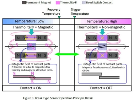
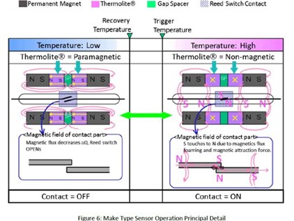
Both thermal and non-thermal reed switches, in the presence of a strong enough magnetic field will change state. With the addition of temperature sensitive magnets the thermal reed switch state is controlled by both temperature AND external fields. As mentioned in the data sheet for the TRS and OHD families, an external magnet can act as an additive or subtractive force on the internal magnetic material of the TRS, and therefore is sensitive to placement, as shown from the chart on the lower left hand of the figure below.
Since the above chart or reference documentation does not specify the field strength of the reference magnetic field this leads to the question of how sensitive is a thermal reed switch to external magnetic fields and how it may affect the temperature trip points? How sensitive is the TRS placement to the temperature trip points? These are some of the questions I plan on answering in my experiments.
Test Equipment & Setup –
Before going over any test results let’s talk a little about the test equipment and setup, and some of the issues that I discovered in the process.
1a) The Helmholtz coil (HC)
The HC is constructed of two parallel coils of radius 3.25 inches separated by the coils radius (3.25”). Each coil consists of 55 turns of 24 AWG single core insulated wire. Electrically, the coils are connected in series so that the magnetic field of each coil is in the same polarity, as shown in the picture below. 
This will generate a uniform magnetic field B at the center between the two coils using the following formula: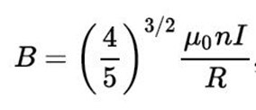
Where µ0 = permeability constant = 4π x 10^-7 Tesla-meter/amps = 1.257x10^-6 (T-m/A)
I = Coil current in amps
R = Coil radius in meters
For my HC with 55 turns and R equals 3.25” or .08255 meter
B = 0.7155 x 1.257 x 55 x I/.08255 = 599 x I (uT-m/A)
Measurement data –
NOTE: Due the power supply output and the recommended maximum current limitations, the maximum coil current tested was 3.0 amps
To verify the magnetic field of the HC I used the SiLab’s Thunderboard Sense 2 as a magnetic field strength sensor (see MFSS below). The board was placed on the heater base with the sensor (see arrow in picture) at the center of the coils, as shown below 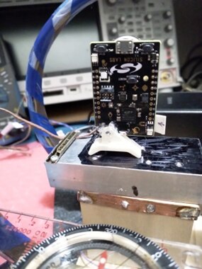
NOTE: The front of the board is facing south in the picture.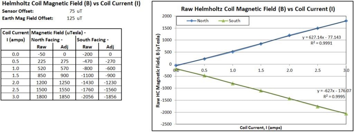
The data adjusted for both the sensor and Earth’s magnetic field offsets are shown below and in the above table.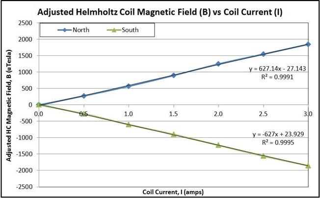
The difference between the calculated 599 and measured 627 scaling factors is most like due to the construction of the coils since it represents, 55 versus 57 coil turns, respectively.
1b) Permanent Magnet (PMag)
As mentioned above, the HC may not produce a large enough magnetic field to affect the thermal reed switches in all tests, so the backup plan is to use a stronger permanent magnet. In that case the following magnet was used.
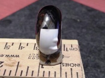

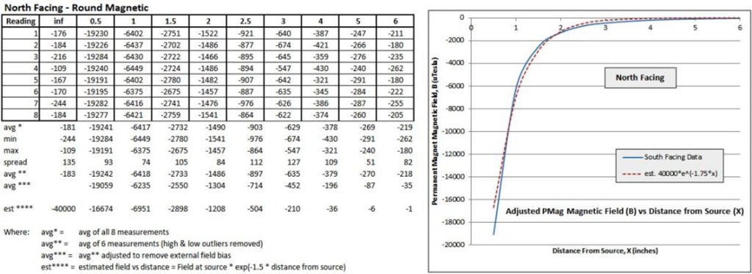
The magnetic field of the PMag was measured using the fixture below, where the front surface of the magnet was placed along the ruler as indicated in the measurement table. The following picture shows the magnetic placement for the 1.5” measurement.
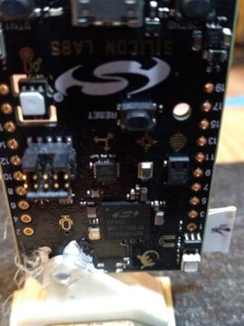

And again the front of the sensor board is facing south. For the measurements, the board was stationary and the PMag was rotated for the north and south readings. Due to noise in the sensor readings, multiple reads were taken and the average shown in the table.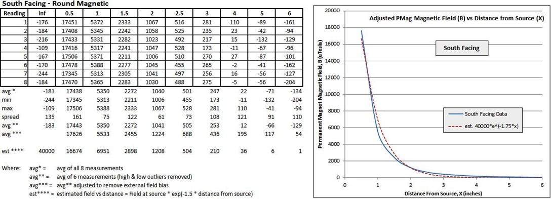
SPOILER ALERT: As cool as the Helmholtz coil seems, as suspected the generated field was not strong enough to result in any major effect on the performance of the TRS, as shown in the test result section. From the standpoint of the TRS, this could be considered a success, but does not answer my fundamental question. From my testing the number of HC windings to achieve the required field strength would have to be 5 times greater (275 vs 55), which was not practical.
2) Magnetic field strength sensor (MFSS)
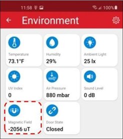
For the MFSS I’m using the SiLab Thunderboard Sense 2 dev kit (P/N SLTB004A). I will use the onboard SiLab Si7210 Hall Effect Sensor along with their Android Thunderboard app to measure the magnetic field strength of both the Helmholtz coil, as well as my permanent magnets. Since I do not have calibration data for the sensor I will have to rely on the limited accuracy specification of the actual si7210 and will only provide a coarse measurement. In addition, the maximum sensor capability is ~ +/-20,000 uT. The figures below show the location of the sensor on the Thunderboard and a screenshot of the Android app display. 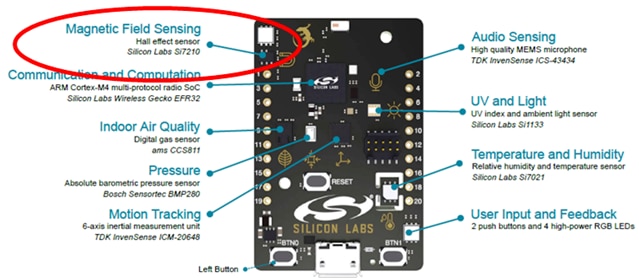
3) AC Power Control Module
For controlling the power to my heating element, I’m using a Dataprobe K-10-IEC power switch. The control lines have two options defined by a jumper internal to the module. The jumper setting determines whether the power is on or off when the control lines are shorted. For a “normally open” (N.O.) TRS/OHD, the module is configured to turn off when the contacts close. For a “normally closed” (N.C.) TRS/OHD, the module is configured to turn off when the contacts open. An LED on the module indicates the power output state.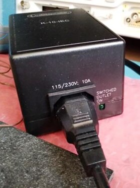
4) Heater element/plate and temperature monitor
NOTE: There are two primary methods for heating the unit-under-test (UUT); 1) direct contact to the heating surface and/or 2) convection where warm/hot air flows across the UUT. For my experiments, direct contact was used.
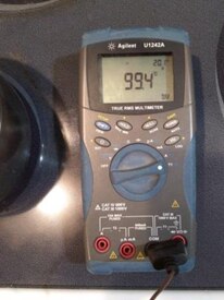
To heat the TRS, the UUT is mounted to the surface of an aluminum heatsink. An AC powered single element soldering iron has been inserted into the core of the heatsink. The soldering iron is powered through the AC power control module. The temperature is manually monitored by an Agilent/Keysight U1242A multimeter connected to a Type K thermocouple (Fluke 80PK-A). The thermocouple is attached to the heatsink at the base of UUT. An array of cooling fans is used to accelerate the cool down process during the power off mode.
The assembly was placed at the center of the HC so that the reed switch was located at the center of the external MagFld. Where the HC wasn’t used, the PMag was mounted a specify distance from the TRS with the respective north or south poles pointing at the unit under test (UUT).
The functional accuracy of the temperature was verified using an ice and boiling water baths, respectively.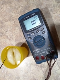
5) Bench DC Power Supply (to drive the HC coils)
A BK 1550, 1 – 36V, 0 – 3A, 108 W bench power supply was used to drive the coils and for the contact bounce tests. For the HC the supply was operating in constant current mode. NOTE: For 24 AWG single core wire the recommended maximum operating current is 3.5 amps to avoid overheating and therefore limited to 3.0 amps in my tests.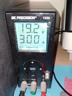
In addition to the above, where necessary wooden fixtures were used for support
Now To Some Tests (or a experimenting we will go …) –
As mentioned earlier my main interesting in my experiments will be to check for effects on TRS activation by external magnetic fields. The data manuals talk a little about the effect of external magnetic field (MagFld) on the mounting and placement of the TRS/OHD, but nothing about the magnitude of the MagFld.
Some construction features of the thermal reed switch may help me determine where to start my testing. For example the actual structure of a reed switch has a set of flat metal elements to make or break contacts in the presence of the magnetic field. This would imply the certain orientations of the reed switch may take more MagFld than other to activate.
Experiment #1:
I built a wooden fixture to hold a TRS to determine any sensitivity to axial rotation. The following is the setup for the M/N M-TRS5-30B (Kit Bin #1), 30 C normally closed TRS. I placed my permanent magnet, PMag, on the base of the fixture under the TRS. I monitored the state of the switch while adding spacers under the PMag. Between adding spacers, I would rotate the UUT to see if the state would change. See picture below:
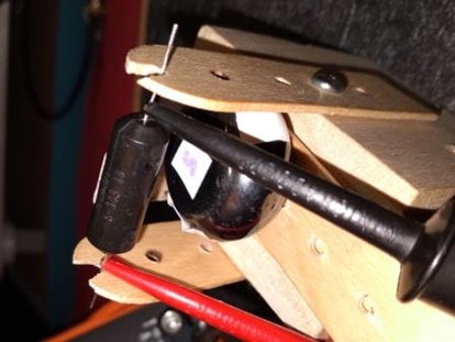
And yes indeed the UUT was sensitive to the axial orientation, but I also quickly found an interesting problem. I try not to make assumption where possible, but in this case I did assume there was some consistency between parts. As I continued testing parts I realize they vary in both markings and physical construction.
Markings –
In looking at the different parts the only consistent markings seem to be two holes in what I labeled the TRS bottom. I assumed they were used in manufacturing to hold the internal components in place during molding since other mold marks, such as seams, seemed to consistent with this, but not all parts had them (see pictures below). The part ID locations were not consistent.
Physical Construction –
The most interesting discovery with the physical construction was the lack of consistency with the magnetic polarity between the same model numbers. For parts that may be sensitive to external magnetic fields the magnetic polarity is not indicated in the data sheet or on the part. Using a compass I had to determine the polarity of each part. Since the holes on the bottom of the parts were uniform, I had to use the direction of the ID labeling for a reference, as shown below. 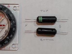


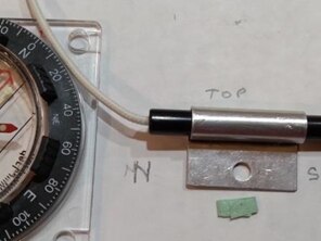
NOTE: UUTs 1, 5, 9 and 12 had the same polarity, but UUTs 6, 7 and 10 did not.
In addition to the polarity, as you will see in the test results, the internal placement of switch and magnets within the molded assembly can affect the performance. Since the TRS has internal magnets the whole assembly has a magnetic polarity. The majority of my testing is with the permanent magnet (PMag) lined up with the center of the UUT. If the internal assembly is not center, results can vary with the change in the polarity of the PMag.
But back to the question at hand, yes the UUT was sensitive to the axial orientation, with the top of the part being the most sensitive. So for most of my tests I faced the top of the UUT toward the magnet field.
Experiment #2:
This section covers the bulk of my testing. As mentioned previously, my first tests included the Helmholtz coil, but the resulting magnetic field was not large enough to make a big difference. The coil current was set to the maximum 3 amps resulting in a ~1900 uT magnetic field at the center of the HC. I reversed the supply polarity to change the magnetic field polarity. NOTE: A picture of the setup is shown at the beginning of this blog.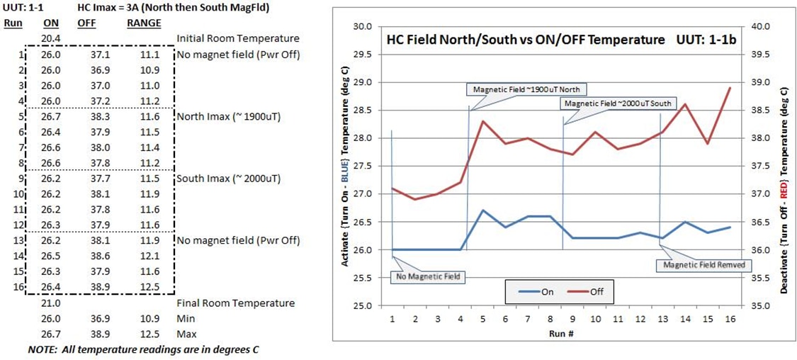
NOTE: The blue line represents the temperature when the TRS either closes for NC switches or opens for NO switches. The red line represents the temperature when the TRS either opens for NC switches or closes for NO switches.
With the exception of the initial first few measurements, the variations in the temperature trip points are smaller with a weaker MagFld, with less than a 1 degree C between the north, south and no field exposure. I was hoping for a larger range. The exception of the first few data points may be due to the temperature gradient time constant of the heating surface at the start of each test.
So let’s try the permanent magnetic…
Experiment #3:
As mention earlier the datasheet for the TRS shows a chart characterizing the effect of the external magnetic field of the temperature trip point, but little or nothing is mentioned about the magnitude of such a field. The chart suggests that a deviation of between 2 and 4 degrees C is possible when a magnet is at the surface of the UUT; respectively for a Make or Break type TRS. The documentation does not say whether these deviations are max or typical. I assume the latter.
NOTE: The setup for this section is outlined under Test Equipment & Setup, subsection 4, Heater element/plate and temperature monitor. 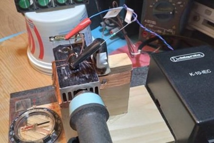
NOTE: As mentioned in the introduction, I tested two samples each of five different parts. The following data represent a sampling of my test results, observations and conclusions. Not all test data is shown, but is available upon request in order to reduce the size of this blog.
Sample UUT5-2: M/N OHD1-30B (Kit Bin #5) 30 oC, OHD series molded axial, Break-Type (i.e. NC)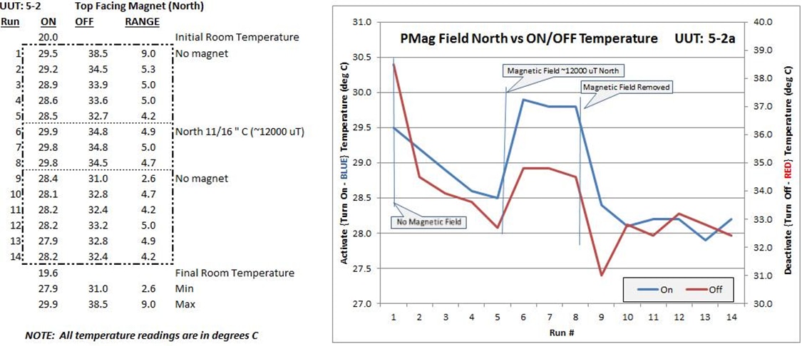
Notes, Observations & Conclusions
Initially no magnet was mounted next to the UUT. After a few test cycles the PMag was place with the North pole facing the center of the UUT at a distance of 0.688” (1.75 cm) for another few cycles. At 0.688” (1.75 cm) the magnetic field is 21000 uT. Finally the magnet was removed and another group of measurements were recorded.
Observation #1: As noted with the HC tests, the initial high temperature (HT) trip point was higher than expected. Again this may be due to the table warm-up time constant and decrease as the UUT stabilizes, but it doesn’t account for the larger momentary dip in the HT trip point when switching from North to South exposure. Could this be some residual magnetic field due to an exposure to the high MagFld? The low Temperature (LT) trip point doesn’t seem to be affected the same amount.
Observation #2: If you eliminated the first readings after a field change the spread between the HT and LT trip points seem to be fairly consistent at 4 to 5 degrees C, regardless the field polarity.
Observation #3: Although the datasheet chart suggests a trip point deviation of 2 degrees C at 0 cm distance, I observed a deviation of ~4 at 1.75 cm.
Sample UUT7-2: M/N OHD1-90B (Kit Bin #7) 90 oC, OHD series molded axial, Make-Type (i.e. NO)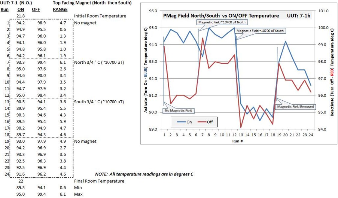
Notes, Observations & Conclusions
Initially no magnet was mounted next to the UUT. After a few test cycles the PMag was place with the North pole facing the center of the UUT at a distance of 0.688” (1.75 cm) for another few cycles, then the magnet is rotated so that the South pole is the UUT at the same distance. At 0.688” (1.75 cm) the magnetic field is +/-21000 uT. Finally the magnet was removed and another group of measurements were recorded.
Observation #1: Like the previous sample, there seems to be and initial spike in the trip points when the MagFld has been add or removed or the polarity switched. Again it may be related to either the table’s thermal mass or a temporary magnet residue from changing the MagFld.
Observation #2: If you eliminated the first readings after a field change the spread between the HT and LT trip points seem to be fairly consistent within the current MagFld, but as you change the field the spread, although consistent increase. Initial spread (no field) was ~2C, then switching to North the spread rose to 3.5C, then switching to South the spread rose again to 5C. Final removal of the MagFld returned the spread to ~4C, still higher compared to the initial spread.
Observation #3: Although the datasheet chart suggests that for make-type TRS a trip point deviation of 4 degrees C at 0 cm distance, I observed a deviation of ~2 to ~4, but at only 1.75 cm.
Observation #4: My final observation was a little more puzzling, since the transition from no field to the North facing exposure showed almost no shift in the LT trip point, where the HT trip point changed +2 degrees C. When changing from North to South facing exposure the HT point changed -3C and the LT point drop 5 degrees C. So I played around with it and noticed that if I moved the PMag across the length of the UUT the trip point changed quite a bit from minimal to maximum deviations. If you move a South field next to the North end of the UUT the field can cancel making the trip temperature higher, but move the North field to the North end of the UUT can have little effect on the trip point. Since the graph shows the result when the PMag is centered on the UUT, the conclusion is the internal assembly is not centered within the molded case. However, I could be mistaken since I don’t have X-ray vision.
Sample UUT1-2: M/N M-TRS5-30B (Kit Bin #1) 30 oC, TRS series molded axial, Break-Type (NC)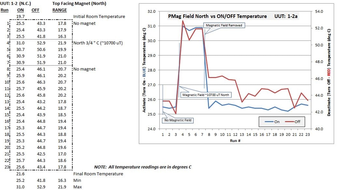
Notes, Observations & Conclusions
Initially no magnet was mounted next to the UUT. After a few test cycles the PMag was place with the North pole facing the center of the UUT at a distance of 0.75” (1.9 cm) for another few cycles. At 0.75” the magnetic field is 10700 uT. Finally the magnet was removed and another group of measurements were recorded.
Observation #1: Although not as pronounced, there is an initial high temperature (HT) trip point spike. A small temperature overshoot also occurred during the initial measurement after the removal of the MagFld.
Observation #2: Unlike the previous samples the spread between the HT and LT trip points seem to be about 3 degrees wider went the magnetic field was presence versus when the field is removed.
Observation #3: After exposure and the MagFld removed it still took a while for the HT trip point to return to the initial “no MagFld” level. This could be the result of some temporary magnet residue field. I saw a similar affect in experiment #4.
Observation #4: As previously note in other samples the trip point deviation was greater than expected. The datasheet chart suggests a trip point deviation of 2 degrees C at 0 cm distance; I observed a deviation of ~5 at 1.9 cm.
Sample UUT12-1: M/N TRS5-30BLR00 (Kit Bin #12) 30 oC, TRS series wire harness axial, Break-Type (NC)
Notes, Observations & Conclusions
Initially no magnet was mounted next to the UUT. After a few test cycles the PMag was place with the North pole facing the center of the UUT at a distance of 0.625” (1.59 cm) for another few cycles, then the magnet is rotated so that the South pole is the UUT at the same distance. At 0.625” (1.59 cm) the magnetic field is +/-13400 uT. Finally the magnet was removed and another group of measurements were recorded.
Observation #1: Like the previous sample, there seems to be and initial spike in the trip points when the MagFld has been add or removed or the polarity switched. Again it may be related to either the table’s thermal mass or a temporary magnet residue from changing the MagFld.
Observation #2: If you eliminated the first readings after a field change the spread between the HT and LT trip points seem to be fairly consistent within the current MagFld, but as you change the field the spread, although consistent increase. Initial spread (no field) was ~6.2C then switching to North the spread rose to only 6.6C, then switching to South the spread did not change significantly. Final removal of the MagFld returned the spread to ~6.4C, still only slightly higher compared to the initial spread.
Observation #3: Although the datasheet chart suggests that for make-type TRS a trip point deviation of 4 degrees C at 0 cm distance, I observed a deviation of only ~2 at 1.75 cm for the South pole exposure and insignificant for North pole exposure.
Observation #4: My final observation was a little more puzzling, since the transition from no field to the North facing exposure showed almost no significant shift in either the LT or HT trip points. When changing from North to South facing exposure both the LT and HT points changed ~ -2C degrees. This is very similar to the results from sample UUT7-2. When the magnetic field was removed the trip points returned to the initial no MagFld trip points.
Observation #5: The result for UUT12-1 seems to be more consistent and may be related to the aluminum mounting sleeve around the assembly allowing for better thermal contact to the heating table and around the body of the UUT.
Experiment #4:
As note in the second and fourth examples of experiment #3, I notice sensitivity to where I placed the PMag along the length of the UUT body. In this experiment the UUT1-2, M/N M-TRS5-30B (Kit Bin #1) 30 oC, TRS series molded axial, Break Type (NC), was run with the North facing PMag placed 0.625” (1.59 cm) from the North, Center then South points on the UUT. The results were:
LT HT Range
North End 19.9 31.4 11.5C
Center 24.6 39.3 14.7C
South End 30.2 44.7 14.5C
Span 10.3 13.3
Notes, Observations & Conclusions
Observation #1: From the results it would appear the placement, as well as orientation is very important to the reliable use of the TRS family. If operated in an environment where a strong MagFld is presence then there could be a variation of 10 degrees in the performance of the TRS depending on the direction the TRS is facing. And on a part where the magnetic polarity is not indicated.
Observation #2: An interesting observation occurred at the LT trip point when testing the North end affect. The time to reach the LT trip point was fairly long. It almost seemed to be “locked” or “hung” in the open position. Further analysis, shows that the TRS was not at fault, but an inherit fault in my test setup. My setup sets in a room temperature environment. The particular test run was performed when the room temperature was 20 degrees. At 20 degrees the TRS wouldn’t switch until I added extra cooling to bring the temperature down to 19.9. So why bring this result up? What if you product was running in an environment where the room temperature varied beyond the range on your TRS.
Observation #3: Related to observation #2, during my experiment the electrically insulated (i.e. non-conductive) magnet came momentarily in contact with the metal leads of the TRS resulting in it switching states (NC -> NO). This occurred when bringing opposing pole together (i.e. the North pole of the magnet to the South pole of the TRS module or the South pole of the magnet to the North pole of the module). The TRS would stay in this new state for >5 minutes or until like poles made contact.
Experiment #5:
I ran some contact bounce tests using a 20.2 ohm, 10 watt, resistor in series with the UUT and powered using a 6.8Vdc power supply. The voltage is measured across the UUT with one lead grounded.
UUT1-1, M/N M-TRS5-30B (Kit Bin #1) 30 oC, TRS series molded axial, Break Type (NC)
The UUT1-1 is a normally closed TRS so the first picture below shows the transition from closed to open when the switch reached the HT trip point. The second picture shows the transition from open to close when the switch reached the LT trip point.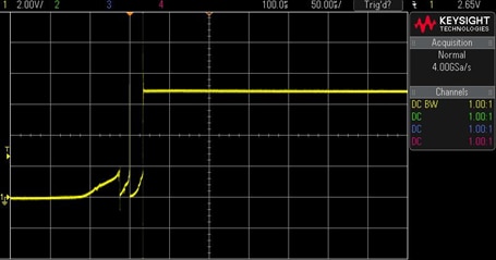
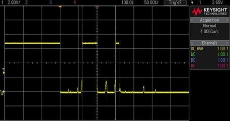
UUT9-1M/N OHD3-115M (Kit Bin #9) 115 oC, OHD series panel mount, Make Type (NO)
The UUT1-1 is a normally open TRS so the first picture below shows the transition from open to close when the switch reached the HT trip point. The second picture shows the transition from closed to open when the switch reached the LT trip point.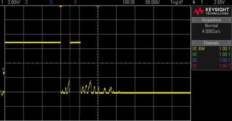

Observation #1: Whether the UUT was a normally open or normally closed TRS the response to the HT and LT transitions were very similar. There seem to be an initial gradual increase in the contact resistance with some bounce, followed by a sharp transition when moving from the closed to open state. When transitioning from the open to close state, the transition and related bounce was sharper, although the contact resistance was noisier before stabilizing.
The next steps (or what I didn’t get too)…
In experimenting on something new it is often the case of the more things I try, the more things I wanted to try. But my wife will tell me my time limited, especially when Spring is here. So the things I would like to try but didn’t get around to:
* The presence of a strong magnetic field can leave a residual magnetic field other ferrous material. A lot like a steel screwdriver becoming magnetized by coming in contact with a PMag, if the TRS came in contact with a strong MagFld could its temperature trip point be changed, either temporarily or permanently?
* Along the lines of my first item, the part’s leads are made out of ferrous metal. Can I magnetically charge them to change the characteristic of the UUT?
* If I dropped or shocked a magnet the MagFld may be changed. Is the TRS susceptible to higher levels of shock and/or vibration?
* If the TRS is mounted in a high vibration environment, could the UUT movement, becoming now moving magnet, generate crosstalk in adjacent circuit’s traces and/or wires?
* It would be interesting to try a smaller heating table. The one I used had considerable thermal mass which could have affect some measurements.
* I would try to improve the thermal mounting of the UUT.
* And of course I would like to build a larger Helmholtz coil to possible test the TRS at AC and pulse MagFlds.
Please let me know if I missed something in the documentation. Also please pardon any typos.
Sincerely,
Gordon Margulieux (a.k.a. gordonmx)
