About me
I'm an engineer with formal studies on IT, CS and neuroscience. Currently I work on diverse projects within and outside the academia. Temperature measurement and control is something I find interesting as temperature has a great impact in living an non-living things (including electronics). Currently I work on a lab that studies temperature-sensitive ion channels, but I've also worked on hobby projects that involve temperature measurement and/or control. Some of these projects can be found on E14:
Temperature control with Labview
Thermal Capacity and Rate of Heat Loss Estimation
Peltier Module Characterization
Capacitor temperature dependence
Introduction
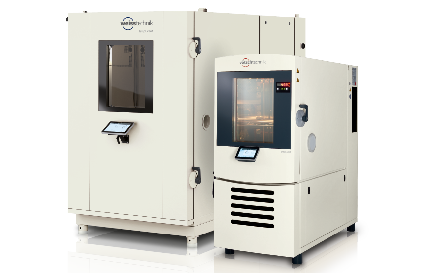
As temperature has a big impact on electronic components, testing electronics at different temperatures can be useful to see if it keeps working as expected on different temperature conditions. Temperature chamber can be used to perform these tests, but commercial temperature chambers, such as the ones in the images tend to be big and expensive.


Previously to test electronic components at different temperatures I've used a beaker filled with mineral oil (as shown in the photo), but this solution has some inconveniences.

Some of this inconveniences are:
- Mineral oil is messy. It's difficult to remove from the submerged electronics and easy to spill
- To test big components a lot of mineral oil is required
- To avoid building up a temperature gradient it has to be stirred. I've stirred it using a magnetically coupled bar, and for the same reason this can affect the measurements.
A better approach
To solve those inconveniences I will use air instead of oil in the project. This of course will add other difficulties due to the lower thermal capacity and conductance of air. Some implementation details that I'll have to figure out are the following:
- The case. Ideally it should have good thermal isolation to avoid heat exchange with the ambient, and in this way require less energy to keep the internal temperature offsetted of the ambient temperature. At the same time the case should allow electrical connections from the inside to the outside.
- A way to blow air inside the chamber to avoid thermal gradients to build up inside. At the same time the fan magnetic field should not affect the measurements.
- Some mechanical structure that can be used to attach the cables, and the electronics that is going to be tested, but at the same minimally block the air flow.
- The heating or cooling element. A Peltier module has the advantage that it would allow me to test the components at cooler and hotter temperature, but the disadvantage than it wont be able to reach the temperatures that could be reached with a resistive element. Since non-outdoor electronics usually gets more hot than cold, it may make more sense to use a resistive element to heat the chamber. Of course even though the internal temperature could reach very high temperatures, it may be limited to maximum operation temperature of the fan. I have a couple of fans that I removed from old PCs, but so far I have not been able to find their maximum operating temperature, so this may require a bit of trial and error.
- The power source. To keep things simple I will probably use a remotely controlled power supply or SMU to power the Peltier module or heating element.
- The ADC. I will probably use a remotely controlled 6.5 digit DMM to make the measurements.
- The control loop. If I decide to use remotely controlled test equipment to control the heat and make the measurements, a computer would be used to perform the control loop computation.
In this project I will explore how to build an inexpensive temperature chamber.
