


Experiment 1 (Initial Setup & Tapping Experiment)
Objective
This experiment is suitable for beginners. I will walk through how to set up the vibration sensor to:
1. Turn on a red LED when vibration is detected
2. Plot a graph on a PC to observe the vibrations
Microcontroller Setup
To make it simple for beginners, I will be coding using Mbed which is a framework for ARM microcontrollers and very similar to the Arduino environment.
The Mbed has an online compiler through the cloud. You must register and login to their website to use the service, but there is no need to install any software.
I am using the Nucleo Board (NUCLEO-H743ZI2) which is Mbed-compatible. There are many powerful boards supported and you can also use other Mbed boards.

Pin Connections
Make these connections.
Sensor Pin | Nucleo Board | Description |
Pin 1 (Red) | 3V3 | Power input |
Pin 2 (White) | A0 | Sensor Output |
Pin 3 (Black) | GND | Ground |
If you haven't read my previous post Experimenting with Vibration Sensors - Characterize RPM of Spinning Devices #2 (Introduction & Unboxing),
I have broken out the pins into a standard 2.54mm header.
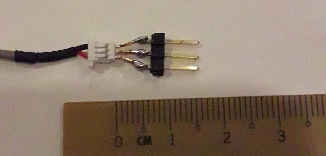
After connections, your setup should look like this
As for the sensor, I mounted it firmly to the table using clear tape for now.

Code for Microcontroller
We shall use the following Mbed code.
    #include "mbed.h"

    AnalogIn sensor(A0);
    DigitalOut green_led(LED1);
    DigitalOut red_led(LED3);

    int main() {
        const uint16_t lower_threshold = 32768 - 7000;
        const uint16_t upper_threshold = 32768 + 7000;

        while(1) {
            uint16_t reading = sensor.read_u16();

            if (lower_threshold < reading && reading < upper_threshold) {
                green_led = true;
                red_led = false;
            } else {
                green_led = false;
                red_led = true;
            }
            printf("%d\n", reading);

            ThisThread::sleep_for(100ms);
       }
    }
I have also published it on my Github repo. You can check for updates there.
Code Explanation
It is a continuous loop which will do the following task indefinitely:
1. Sample the vibration sensor using the ADC
2. Check if the vibration detected is about a certain threshold, then toggle an LED
3. Send the vibration sensor values to the PC using the serial port (printf)
Sensor Threshold Explanation
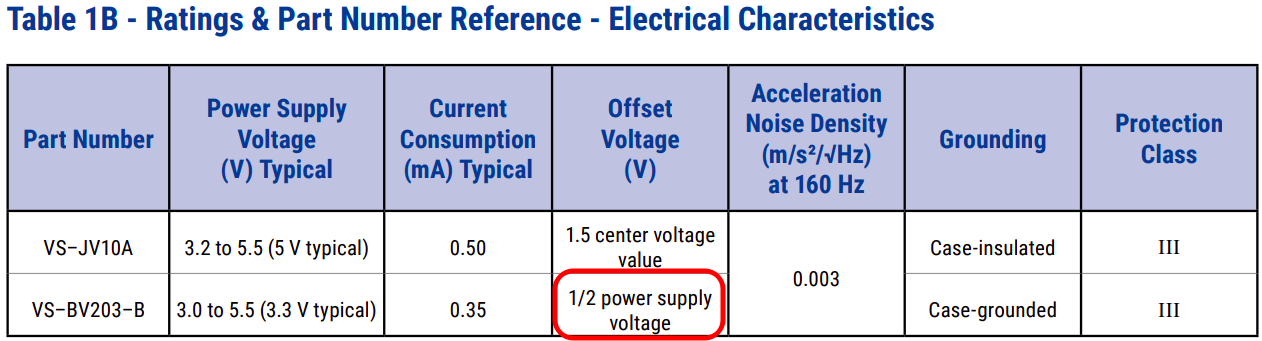
When there is no vibration, the ADC reading will be exactly centered at 50%. (From the datasheet, Table 1B states that the offset voltage is “1/2 power supply voltage”.)
Depending on the direction of vibration, the voltage can go up or down in one event. Hence, we need to check for 2 thresholds, an upper and lower threshold.

Note that this board has a 16-bit ADC, where 50% is 32768. The thresholds are set around this nominal value.
Guide for Mbed programming
First create an account and login to the Mbed IDE website using your account.
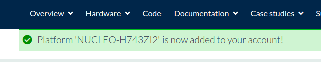
Go to the NUCLEO-H743ZI2 platform page and click on “Add to your Mbed Compiler”

Once it is confirmed that the platform has been added, go back to the IDE.
Click the top right button to change the platform.
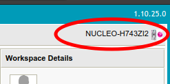
A window will pop up with all your boards. Select NUCLEO-H743ZI2.

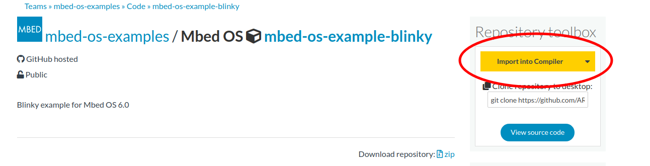
Let’s first import an example Blinky program to ensure our board works properly.
Open up the mbed-os-example-blinky page and click on “Import into Compiler”.
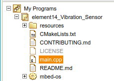
Enter your own project name and click on Import.

The project will be seen in the Workspace and you can open up main.cpp.
On the top, click on Compile. It will download the hex file.

Connect the Nucleo board and a NUCLEO drive will appear. Drag & drop the hex file into the NUCLEO drive to program it.

Verify that the board LED is blinking.

—
Now, replace with our code from above.

Compile and drag & drop onto the drive again.
We are ready to do our first test!
First Test Results
I have created the code above, that when the amount of vibration reaches a threshold value that we have set, the Red LED will turn on
Here, by tapping on the sensor, we can confirm the behavior as the LED is seen toggling on and off.
In my code, the microcontroller will also write the values to the PC using the serial port.
It is possible to visualise the values by doing a plot of the values over time.
The most simple one is to use the Arduino Serial Plotter tool.

Tapping will cause a short vibration. This is the graph of how the sensor behaves when tapping on the sensor.
Hard vs Soft Taps

Problems faced
However, we now face a small problem… If you have noticed, I have added a delay of 100ms in the code. This is because if I reduce the delay, it will be too fast and the Arduino Serial Plotter will start to lag.
In the next blog post, I will code my own graph plotter program using Python to display extremely fast data. In the future experiments, it is necessary to get rid of the delay to plot a smoother graph and also do more accurate analysis.
Conclusion
In this post, I demonstrated how we can use the Mbed online compiler to quickly get the project code up and running.
We learnt that this sensor is very sensitive and we can distinguish the hard taps and soft taps. The graph can be plotted on the PC.

Although I have faced a small setback in plotting the graph, I will solve it in the next experiment! Please leave a comment if you would like to suggest anything I should try.