element14 Community
element14 Community
    Register Log In
  • Site
  • Search
  • Log In Register
  • About Us
  • Community Hub
    Community Hub
    • What's New on element14
    • Feedback and Support
    • Benefits of Membership
    • Personal Blogs
    • Members Area
    • Achievement Levels
  • Learn
    Learn
    • Ask an Expert
    • eBooks
    • element14 presents
    • Learning Center
    • Tech Spotlight
    • STEM Academy
    • Webinars, Training and Events
    • Learning Groups
  • Technologies
    Technologies
    • 3D Printing
    • FPGA
    • Industrial Automation
    • Internet of Things
    • Power & Energy
    • Sensors
    • Technology Groups
  • Challenges & Projects
    Challenges & Projects
    • Design Challenges
    • element14 presents Projects
    • Project14
    • Arduino Projects
    • Raspberry Pi Projects
    • Project Groups
  • Products
    Products
    • Arduino
    • Avnet Boards Community
    • Dev Tools
    • Manufacturers
    • Multicomp Pro
    • Product Groups
    • Raspberry Pi
    • RoadTests & Reviews
  • Store
    Store
    • Visit Your Store
    • Choose another store...
      • Europe
      •  Austria (German)
      •  Belgium (Dutch, French)
      •  Bulgaria (Bulgarian)
      •  Czech Republic (Czech)
      •  Denmark (Danish)
      •  Estonia (Estonian)
      •  Finland (Finnish)
      •  France (French)
      •  Germany (German)
      •  Hungary (Hungarian)
      •  Ireland
      •  Israel
      •  Italy (Italian)
      •  Latvia (Latvian)
      •  
      •  Lithuania (Lithuanian)
      •  Netherlands (Dutch)
      •  Norway (Norwegian)
      •  Poland (Polish)
      •  Portugal (Portuguese)
      •  Romania (Romanian)
      •  Russia (Russian)
      •  Slovakia (Slovak)
      •  Slovenia (Slovenian)
      •  Spain (Spanish)
      •  Sweden (Swedish)
      •  Switzerland(German, French)
      •  Turkey (Turkish)
      •  United Kingdom
      • Asia Pacific
      •  Australia
      •  China
      •  Hong Kong
      •  India
      •  Korea (Korean)
      •  Malaysia
      •  New Zealand
      •  Philippines
      •  Singapore
      •  Taiwan
      •  Thailand (Thai)
      • Americas
      •  Brazil (Portuguese)
      •  Canada
      •  Mexico (Spanish)
      •  United States
      Can't find the country/region you're looking for? Visit our export site or find a local distributor.
  • Translate
  • Profile
  • Settings
Experimenting with Vibration Sensors
  • Challenges & Projects
  • Design Challenges
  • Experimenting with Vibration Sensors
  • More
  • Cancel
Experimenting with Vibration Sensors
Blog Vibration Sensor - First Look
  • Blog
  • Forum
  • Documents
  • Polls
  • Files
  • Events
  • Mentions
  • Sub-Groups
  • Tags
  • More
  • Cancel
  • New
  • Share
  • More
  • Cancel
Group Actions
  • Group RSS
  • More
  • Cancel
Engagement
  • Author Author: ralphjy
  • Date Created: 6 Dec 2020 12:18 AM Date Created
  • Views 1409 views
  • Likes 8 likes
  • Comments 3 comments
  • experimenting_with_vibration_sensors
  • kemet vibration sensor
Related
Recommended

Vibration Sensor - First Look

ralphjy
ralphjy
6 Dec 2020

Sensor hookup

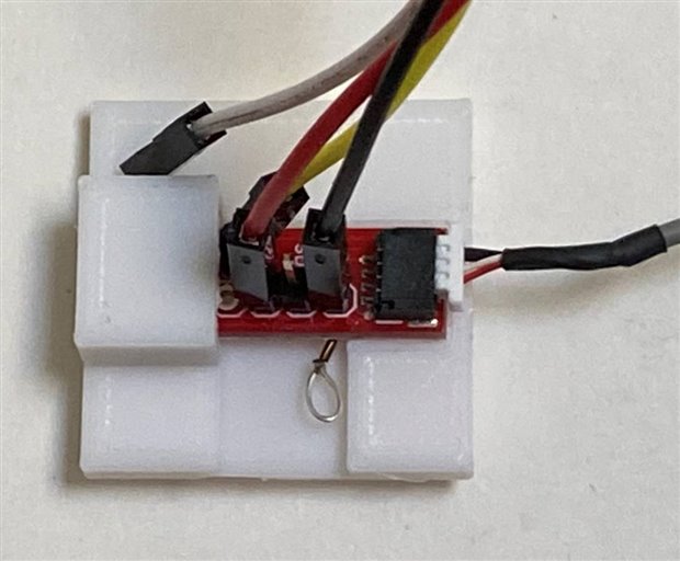
I've been reading with interest all the clever solutions to interfacing the tiny connector on the end of the vibration sensor cable.  I had also ordered the recommended SMD mating connectors.  When I received the connectors, I pretty much decided that I couldn't easily make a robust adapter so I was just going to cut the existing connector off and attach a larger Grove connector because I have lots of cables and boards that use the Grove system.  I've recently been using a lot of boards with Grove and Qwiic (Stemma-QT) connectors - most recently on the Adafruit QT Py.  I had purchased a Sparkfun Qwiic adapter board https://www.sparkfun.com/products/14495  to allow me to interface breadboard jumper cables to Qwiic sensors.  It turns out that the Qwiic coinnector is a 4 pin version of the 3 pin connector on the vibration sensor cable and that cable will plug into the adapter as I've shown below.  Of course, you have to be careful to use the correct 3 pins and I had to make SCL the GND pin but otherwise it's a mechanically robust solution.

image


I printed a holder for the adapter board to keep it stable (flat) when I attach jumpers or probes to it for testing.

image


In actual use I'll probably use the other Qwiic connector (obscured by the housing) with an adapter cable to a Grove connector which I can plug directly into a Wio Terminal for data collection and processing.


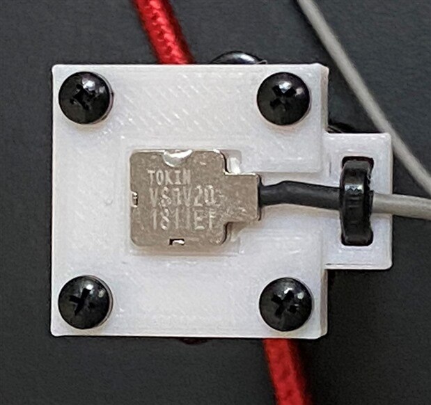
I also attached the sensor body to the mounting plate that I had printed using double sided thermal adhesive tape (because it works well as double sided tape).  And I added strain relief for the cable.  Here the mounting plate is shown attached to the riser on the microphone stand.

.image


First test

Before diving in to data collection I thought it would be good to sanity check my setup with a scope.

We expect the sensor signal to be about VCC/2 (+1.65V) and swing +/- around that level.

Here is a scope capture of the response to a quick tap on base of the stand.

image


The quiescent DC level is +1.7V which is good.  I'm a little concerned about the quiescent noise level.

Here is a closer look at the noise:

image


I then tried tapping about 18 inches away from the stand on my wood desktop.

image


It will be interesting to see if I can discern footsteps on my hardwood floors.  Time to start working on a program for data collection image.


Links to my other blogs for this challenge

Person Identification using Footstep Vibration Patterns

Vibration Sensor Setup

  • Sign in to reply

Top Comments

  • ralphjy
    ralphjy over 4 years ago in reply to zst123 +1
    The tape might have some small effect. The dimension before compression is 0.2mm. I’m more concerned about whether I’ll get too much attenuation because I’m not doing a direct attach to the floor. I guess…
  • dubbie
    dubbie over 4 years ago

    It will be interesting to see the sensitivity of this sensor. The noise you see might just be background vibration. It could be tricky to try and eliminate that.


    Dubbie

    • Cancel
    • Vote Up 0 Vote Down
    • Sign in to reply
    • More
    • Cancel
  • ralphjy
    ralphjy over 4 years ago in reply to zst123

    The tape might have some small effect.  The dimension before compression is 0.2mm.


    I’m more concerned about whether I’ll get too much attenuation because I’m not doing a direct attach to the floor.  I guess I’ll see if I need to change my method after getting some data.


    The main requirement for me  is to be able to distinguish unique vibration patterns.  The absolute frequencies and amplitudes of the signals is not as important.

    • Cancel
    • Vote Up +1 Vote Down
    • Sign in to reply
    • More
    • Cancel
  • zst123
    zst123 over 4 years ago

    Cool to see that the Qwiic connectors fit nicely! I have never used those before. image Nice mounting you have there too, wish I had a 3D printer as well!

    So far, I mount my sensor using clear tape. I realized that I must stretch my tape with enough downward pressure so that the vibrations are fully felt by the sensor. Looks like you are using a foam-like adhesive tape. Do you think it will dampen the vibrations as well and affect the results?

    • Cancel
    • Vote Up 0 Vote Down
    • Sign in to reply
    • More
    • Cancel
element14 Community

element14 is the first online community specifically for engineers. Connect with your peers and get expert answers to your questions.

  • Members
  • Learn
  • Technologies
  • Challenges & Projects
  • Products
  • Store
  • About Us
  • Feedback & Support
  • FAQs
  • Terms of Use
  • Privacy Policy
  • Legal and Copyright Notices
  • Sitemap
  • Cookies

An Avnet Company © 2025 Premier Farnell Limited. All Rights Reserved.

Premier Farnell Ltd, registered in England and Wales (no 00876412), registered office: Farnell House, Forge Lane, Leeds LS12 2NE.

ICP 备案号 10220084.

Follow element14

  • X
  • Facebook
  • linkedin
  • YouTube