


Sensor design
Sensor construction requirements
As it was described in the first part of my project blog, I want to build a central monitoring station and several sensors installed in different enclosures, gathering data for further analysis. Using this approach, all the data will be in one place and - as experiment involves testing in adverse conditions, making failures possible - somewhat protected from sensor loss.
Monitoring station was described in the third part of my blog, now it's time to describe construction of the sensor.
As it was previously mentioned, I want my sensors communicate using WiFi (to utilize existing communications infrastructure), be battery powered (for additional flexibility - I don't want to be forced to make additional holes in my enclosures) and inexpensive (so they can be easily replaced if destroyed during experiment). At least one working ADC input will be a plus - will allow for monitoring of battery voltage.
I have decided to build them using ESP8266 SoC modules - they are inexpensive, have WiFi builtin - but there is a problem with battery operation.
As described in ESP8266 datasheet (tables 3-4 and 5-2), power consumption depends on usage and can be quite high.
| Power mode | Description | Power consumption |
| Active (RF working) | WiFi TX packet | 120-170mA |
| Active (RF working) | WiFi RX packet | 50-56mA |
| Modem sleep | CPU is working | 15mA |
| Light sleep | 0.9mA | |
| Deep sleep | Only RTC is working | 20uA |
| Shut down | 0.5uA |
It means that some power saving measures are necessary - fortunately, sensor doesn't need to be working all the time, periodic wake-up will be sufficient.
Initial tests
First, proof-of-concept sensor was NodeMCU board based and looked like this:

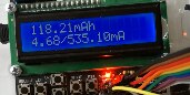
It worked, but the power consumption was unacceptable. As expected duty cycle of the sensor is like one reading every ten minutes, some power measurement method was needed. As I don't currently own a power profiler, I had to build my own (primitive but sufficient in my opinion).
It turns out that chipset power consumption is one thing, but typical board includes additional components that can also be power-hungry. Those components are usually: USB-to-UART bridge and power regulator (plus internal structure of the ESP module - that usually includes at least external flash memory). Some boards even have always-on LEDs as power indicators...
For example - commonly installed 3.3V linear power regulator (based on TI LM1117 datasheet) consumes about 5mA when idle and needs additional several mA of load to maintain regulation.

Making things worse, LM1117 has about 1.2V dropout voltage, which makes use of standard Li-Ion battery problematic.
ESP8266 has working voltage range is 2.5-3.6V but if installed in a module with additional memory it's operating range is usually narrowed to 3.0-3.6V.
Standard Li-Ion battery with nominal voltage of 3.6V has voltage range from about 2.5V (recommended discharge end voltage) to 4.2V (charge end voltage).
So - using one Li-Ion battery, 3.3V LM1117 will be in undervoltage condition all the time, so another LDO type is needed.
But - returning to our NodeMCU construction - the problem was far worse that power-hungry LDO. Initial tests of switching to deep sleep mode during inactivity revealed that peak consumption is about 240mA, but idle consumption nears 100mA. Additionally, ADC input was not working (returning near-zero constant readings) - this can be easy to explain: ADC in ESP8266 is used mainly for WiFi calibration and it's frequent usage during WiFi operation is oficially discouraged, so it may be disconnected in this particular clone. Not good, let's find something better.
Second prototype
Board selection
Initially, ESP01 module seemed to be an ideal candidate - very cheap, easily connected (no need of breakout board), no unnecessary components. Paired with LDO like HT7333 (250mA, 90mV dropout voltage, 7uA quiescent current) could be really power-efficient. But - as it has only 8 external pins:
- no ADC pin is available, so no battery monitoring,
- as deep sleep auto wake mode uses GPIO0 to reset CPU after sleep period elapses, only one GPIO pin is available - so no I2C, only one-wire sensors possible,
After some additional searching, Wemos D1 mini (clone) turned up as promising candidate. It is still equipped with USB-to-UART bridge, but has power-efficient LDO (ME6211) and enough GPIO for our project.
First one looked like this:

and worked great - during sleep period it consumed less than 1mA.
So second one was bought (the same part from the same seller - reputable online shop, but using their account on local Ebay-like portal) - and this one was of different make:
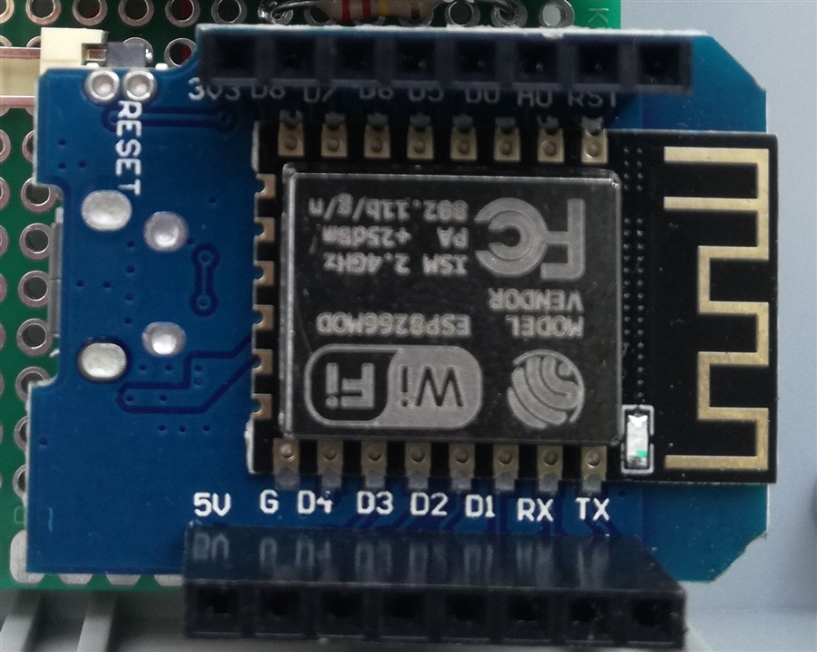
As can be seen, this board uses ESP module instead of bare chips and is more power-hungry - consuming about 20mA when sleeping.
Power supply
Next part - power supply. Initial tests using some powerbank module (with 5V USB input and output) have failed - as this module had some sort of power-saving feature, disabling output (lowering voltage near battery output level to be exact) when current draw was too low, ESP wasn't able to wake from sleep on partially depleted battery.
As a side note - problem with powering-off powerbanks seems to be well known and was addressed in - for example - Staying alive with the 555 project.
Taking into consideration that ME6211 has dropout voltage of about 100mV, it theoretically could be powered directly from Li-Ion cell (working as unregulated power supply below 3.4V), but searching for battery charger module ended with unusual find - J5019 module - that combines TP4056 battery charger with step-up converter (unfortunately without undervoltage protection). Setting output voltage to ~ 5V makes equivalent of powerbank, but without that problematic power-saving mode.

Sensor selection
And the last part - sensors. I have decided to use popular DHT22-like sensors (AM2302 with one-wire interface and AM2320 with I2C interface). They can be powered from 3.3V so could be directly interfaced with ESP module.
That have led to sensor module schematics as a below:

It has voltage divider to measure battery voltage (designed for direct ESP8266 connection - with allowed voltage range of 0-1V. Wemos module has additional divider built-in, allowing for 0-3.3V input voltage range - which is somewhat limiting the precision of measurements in my case) and one sensor connected.
Data gathering
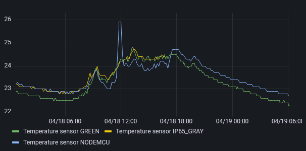
Below are some initial measurements (sensors running next to each other in the office room):
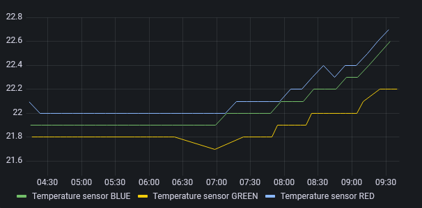
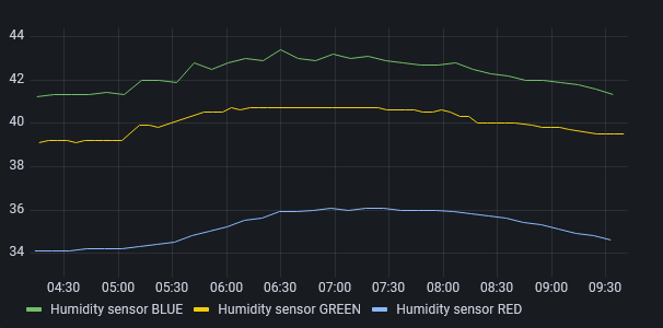
As can be seen, although temperature measurements are similar, humidity difference between sensors is significant. In the graph above, series BLUE and GREEN are from AM2302 sensors and RED one is from AM2320 - which not only reports data significantly lower than two others but seem to have much slower response (graph looks smoother than two others, filtering out rapid changes detected by other two).
As AM23xx sensors - despite having supply voltage range of 3.3-5.5V - are recommended to be operated at 5V, another test was performed. NodeMCU sensor board was modified to allow for supplying AM2320 sensor from 5V (bidirectional level translator was connected on I2C lines).
And measurement data was gathered (between two vertical markers; peaks near reconfiguration time are artifacts, caused by handling of the board, thus increasing it's temperature and humidity).
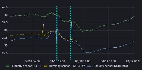
No significant difference was seen - so it seems that observed disparity is not caused by insufficient supply voltage but rather difference between sensors (maybe some of them were of substandard quality or measurement algorithms were different between models).
Using this data, AM2320 module was removed from the test and AM2302 sensors were considered usable for monitoring - offset between different sensors looked constant and reaction to environmental changes similar. As we plan to focus mainly on trends in data, some offset between series seems acceptable at this point.
Sensor with battery pack installed in one of enclosures prepared for our test looks like on the photo below - as it is battery powered, no additional holes are necessary. One can clearly see jumper cable enabling deep sleep RTC wake-up that is connecting D0 and RST pins - it has to be removed during module programming, so no permanent connection was made.

In the next part I plan to focus on enclosure and connector construction details that would be important for test results.