


Ever had to measure power consumption of some device with variable work-cycle? With low consumption when idling and spikes from time to time - every 10 minutes for example? And without dedicated tool-set - like Power Profiler Kit?
I recently had such situation - wanted to measure power profile of ESP8266 module waking from deep-sleep to read sensor data and publish it, then going to sleep again.
So - how to quickly build some crude metering solution? Using Arduino board of course!
And this is how began BBIPP (Breadboard-borne Improvised Power Profiler). It consists of (clone of) Arduino Uno R3 board, (clone of) LCD KeyPad Shield and interfacing circuit.
First iteration of interface consisted of 1 Ohm resistor placed in ground connection of DUT (device under test) with parallel diode protecting Arduino from reverse polarization. Signal from resistor was connected to A1 pin of Arduino (A0 is occupied by keypad's resistor ladder - all keys of the shield are connected to the same analog pin, and can be differentiated by voltage level measured).
Schematics of this shield can be found in the link below:
https://cdn.robotshop.com/media/v/vel/rb-vel-143/pdf/lcd-keypad-shield-arduino-schematic.pdf
Next step - Arduino: Atmega328P has 10 bit A/C converter, with reference voltage that can be set to:
- supply voltage
- internal 1.1V reference
- external reference
External reference was rejected because of additional complication - it had to be as simple as possible. Supply voltage was considered unreliable - it varied from 4.8V (using USB power from PC) to 5.1V (from phone charger) when using USB port as power supply, and connecting external 12V regulator generated so much heat that it could affect precision of measurements.
By elimination, internal reference was chosen - it was measured (at Aref pin) as 1.088V - so pretty close to the specification. Additionally it provides the most precise data - ADC has 1024 levels (10 bit), so every level translates to about 1mV of input voltage (thus out profiler can theoretically measure currents between 1mA and 1A, using proposed 1 Ohm resistor).
Now - how to improve measurement range of our device? We can use different resistor - but it can impede operation of DUT (even on 1 Ohm at 1A voltage drop is 1V - and it generates 1W of heat). Switching resistors during runtime seems impractical - we will need to switch them very fast to follow current variations.
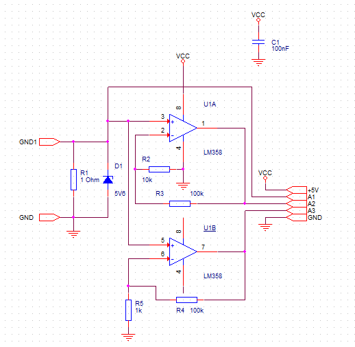
In the next step auto-ranging using two opamps was implemented. Atmega828P includes analog multiplexer and - according to the datasheet - voltages greater than reference are represented as values near 0x3FF - so it is not going to be destroyed by measuring voltages near Vcc even using internal 1.1V reference.
It means we can connect signal amplified by different ratios to different analog inputs and select one that is both in-range and as far from zero as possible. As opamp (LM358) is powered from 5V, output voltage cannot exceed Vcc (so it is safe for Arduino) - and input was protected with 5.6V Zener diode instead of reverse-polarised switching diode to protect both from reverse connection and overvoltage. Schematics of interface circuit is as below:
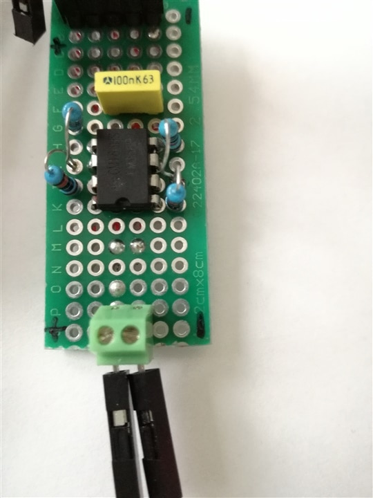
and it initially looked like this:

Next step - the code. Using attached (below) sketch, Arduino displays: momentary current consumption, maximum current consumption and counter of mAh calculated from measured current samples.
power_profiler.zip
As display shield includes some keys, they were used for simple control inputs: UP and DOWN control backlight brightness and SELECT zeroes displayed data (mAh counter and maximum current latch).
As a side note - all keys are connected to resistor ladder to limit required connection count. Unfortunately - this ladder is connected to Vcc (which is out of range when using 1.1V reference) and switching references before every keypad reading looked unreliable - so the shield was modified by installing 470 Ohm resistor between A0 and GND, creating voltage divider. Resistor value was calculated using schematics of original DFRobot DFR0009 to obtain maximum voltage of about 1V, but measured voltage turned out to be about 650mV - it seems that clone uses different resistor values. Voltage levels representing each key were calculated after measuring voltage at A0 when given key was pressed - so they can be different for different clone and below line of code should be modified as needed:
static int levels[KEYNO] = { 50, 350, 480, 550, 590 };SELECT button has one additional usage - when pressed during boot-up of Arduino it forces simple offset measurement procedure - when inputs are connected together (zeroed) it reads mean values of every input (mainly offset voltages of amplifiers) and prints them on the serial console.Owner can then use them to modify constant array as below and reprogram Arduino:
const double analogOffset[ANALOGINCNT] = { 0, 5.1, 4.1 };
And the question everybody is asking in this competition - can it drive you crazy? Of course - unreliable connections of breadboard was driving me crazy to the point when I moved everything to the proper universal PCB, when unexplained behavior ended. This version is displayed on the following photo:
So - how fast one can build such a meter? It took me a few hours - mainly debugging problems that turned out to be related to unreliable bread-board connections...
Bill of materials
Arduino Uno R3 board
DFRobot DFR0009 LCD/keypad shield
D1 5.6V Zener diode
and mandatory video: