


In this blog, I'll go through setting up the communications hardware, and software setup for video streaming and data logging.
Internet Connectivity
I decided on using an EM7455 WWAN card, typically used in laptops, to provide the system with internet connectivity. This module also has a built-in GPS receiver, so I won’t have to add a separate one later.

Newer WWAN cards use an M.2 connector, which is typically associated with PCI-e or SATA connectivity, but these modules only utilize USB.
Initially I thought I’ll have to make a custom PCB for this too, but I found several ones on Amazon that already do exactly what I need. Their purpose is to provide the module with 3.3V, have a SIM card slot that directly connects to the M.2 slot, and a male USB port also directly going to the M.2 connector.
The RF connectors on the module at first look like u.FL, but they are MHF4. Thankfully their PCB footprints are similar enough that I was able to solder on some u.FL connectors instead, and use cheap SMA pigtail cables.
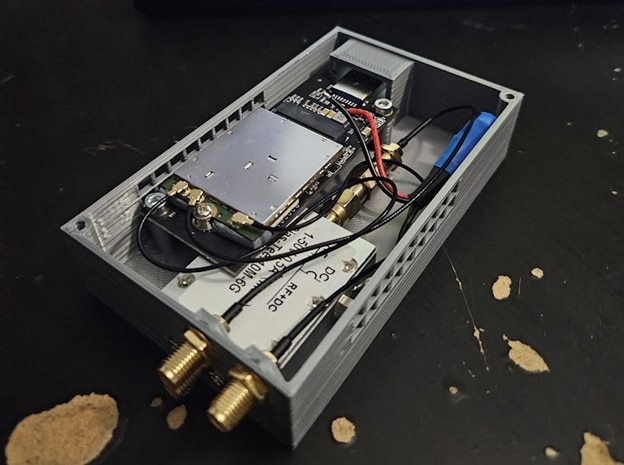
I also added a DC injector for the GPS port, to power an active patch antenna. (there are 3 SMA connectors total, the bottom one is obscured in this image - two for 4G with diversity, one for GPS).
Software setup
Setting up the module to work with Linux was really confusing at first. I couldn’t find any guides that worked, some of them are simply wrong(or don't apply to my module, even though it's the same model), some of them are really outdated. The modules can also have different OEM configurations that lock them down and/or need different magic values.
Here’s a quick overview:
These modules can expose multiple different kinds of network interfaces and serial ports. First step is to enable everything we need. In the datasheet for my module, this is referred to as “USB composition”. I ended up with 3 serial ports(two for 4G control related communication, one for GPS data) and one network interface.
Afterwards, use ModemManager to actually set up the modem. I got stuck here for a while, turns out I needed to do an “FCC unlock”, which is done by using this command:
sudo ln -sft /etc/ModemManager/fcc-unlock.d /usr/share/ModemManager/fcc-unlock.available.d/*
Then I was able to set everything up and have internet access. This setup wasn’t persistent though, so instead of manually configuring the modem each boot, I used NetworkManager to handle the WWAN connection. nmtui provides a graphical setup to configure all required parameters, so this part was simple enough. This approach still uses ModemManager in the background, just managed by NetworkManager, with the added benefits of automatically setting up the module on boot, and also handling reconfiguring everything if the module gets unplugged and plugged back in.
Sending AT commands to the modem for configuration purposes is a bit tricky though, as ModemManager "takes" the control serial port for itself. The solution is to use ModemManager in debug mode, by creating a systemd service override.
sudo systemctl edit ModemManager
Then clearing the previous ExecStart value by setting it to nothing, and afterwards adding our new value:
[Service]
ExecStart=
ExecStart=/usr/sbin/ModemManager --debug
If the blank "ExecStart=" line is omitted, the value configured underneath will be appended to the original value instead of overwritten.
Now it is possible to send AT commands through ModemManager, and get the output back too. For example, enabling the DC output on the GPS port looks like this:
sudo mmcli -m 0 --command='AT+WANT=1'
If someone finds this blog post looking for help with setting a modem up, here are some resources that turned out to be super useful:
https://wiki.archlinux.org/title/Mobile_broadband_modem
https://github.com/danielewood/sierra-wireless-modems
https://florian.sesser.at/work/fcc-unlocking-sierra-wireless-em7455-and-others-on-linux/
GPS
Setting up GPS was similarly painful. Even after enabling everything through AT commands, nothing appeared in the serial port that should be outputting NMEA data.
The issue turned out to be a magic command needs to be sent to the serial port. It looks like this might also depend on firmware, because a lot of posts mention a different command than what works for me. I had to send “$GPS_START” to /dev/ttyUSB1 at 9600 baud for the NMEA output to start.
Here are all the AT commands I issued to configure GPS:
Enable "hidden" commands:
sudo mmcli -m 0 --command='AT!ENTERCND="A710"'
Enable GPS:
sudo mmcli -m 0 --command='AT!CUSTOM="GPSENABLE",1'
Use dedicated GPS antenna port instead of sharing with the 4G port:
sudo mmcli -m 0 --command='AT!CUSTOM="GPSSEL",0'
Enable GPS autostart, use standalone fix, 255 second max wait time for fix, no requested min accuracy, 1 seconds between fixes
sudo mmcli -m 0 --command='AT!GPSAUTOSTART=1,1,60,4294967280,1'
Set A-GPS to use User Plane instead of Control Plane:
sudo mmcli -m 0 --command='AT!GPSMOMETHOD=1'
Enable NMEA output and set output rate to 1hz:
sudo mmcli -m 0 --command='AT!GPSNMEACONFIG=1,1'
Enable all NMEA sentences:
sudo mmcli -m 0 --command='AT!GPSNMEASENTENCE=7B9B'
Enable all positioning modes:
sudo mmcli -m 0 --command='AT!GPSPOSMODE=7F'
Enable DC power output for the GPS antenna port:
sudo mmcli -m 0 --command='AT+WANT=1'
And then send the magic string $GPS_START to the NMEA serial port.
After I got GPS configured on the modem side, I installed GPSD, and changed a line in its configuration file at /etc/default/gpsd to point it to the correct serial port.
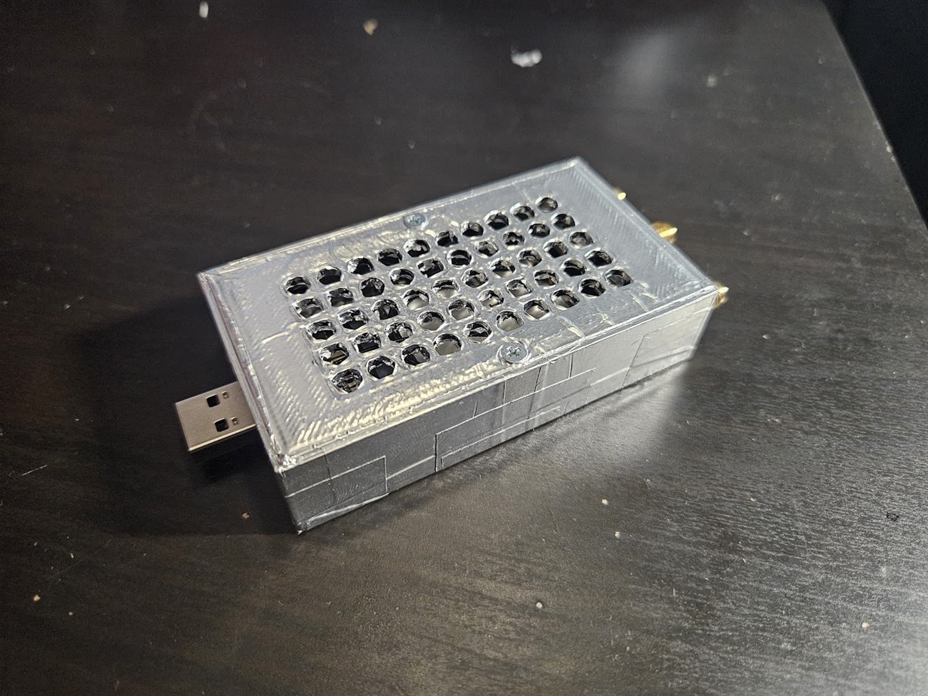
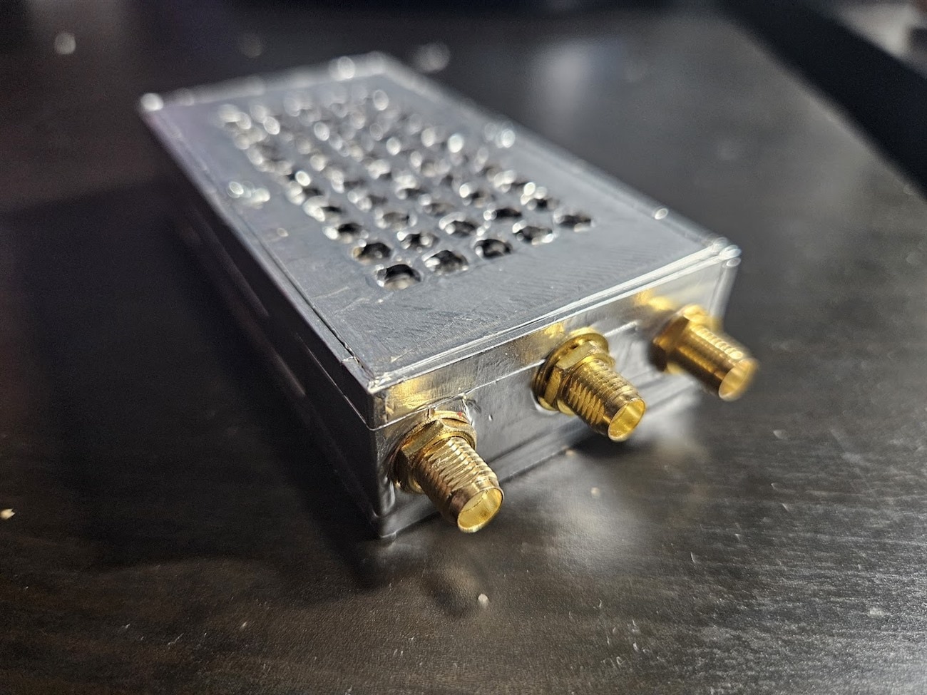
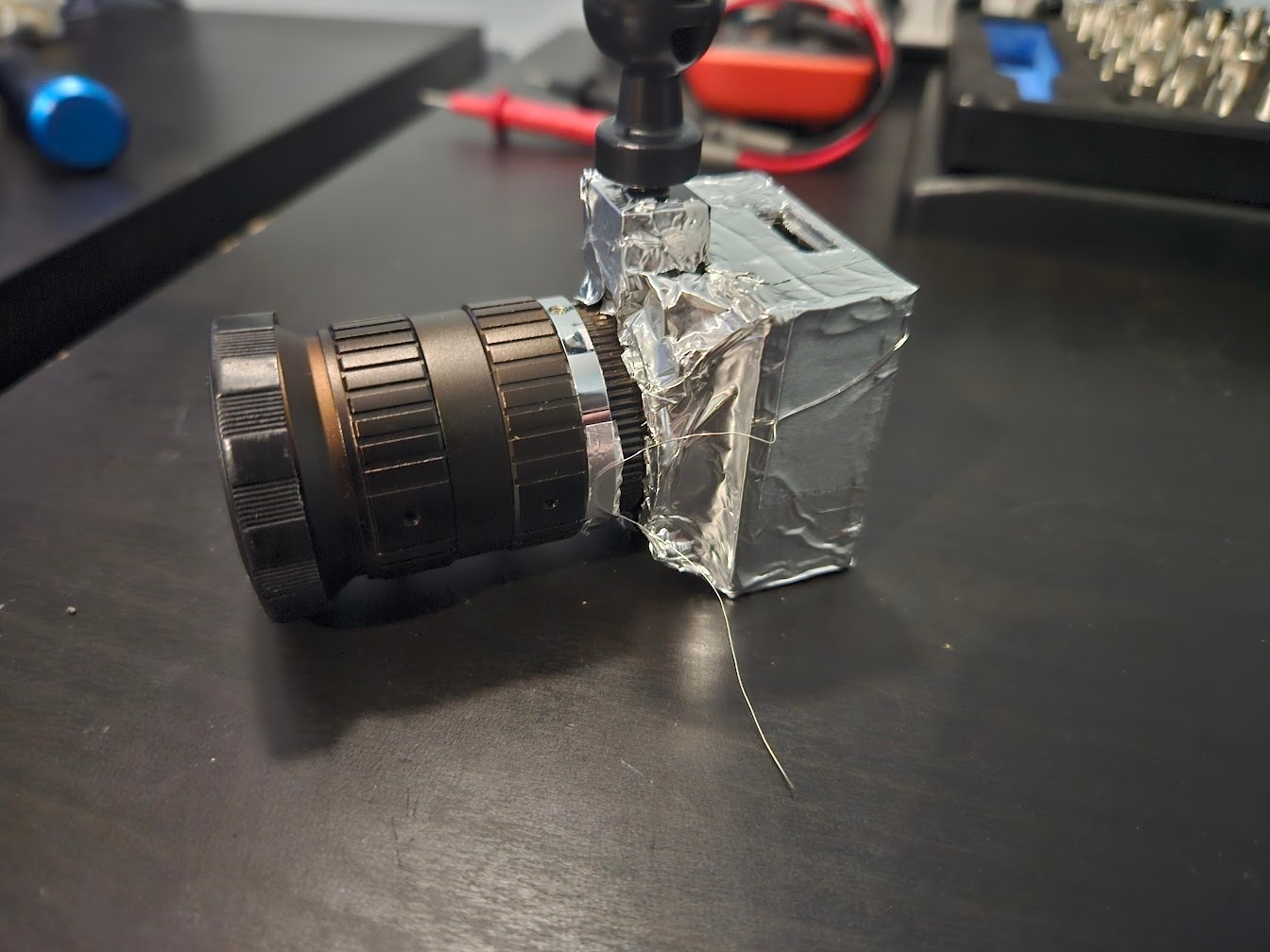
I only discovered the option for enabling 3.3V output on the GPS port while trying to get the module to work under Linux, meaning my bulky DC injector was redundant. I didn’t really like the enclosure I made anyways, and the 4G module interfered with the GPS receiver, so I made a new, significantly smaller enclosure, featuring lots of shielding:
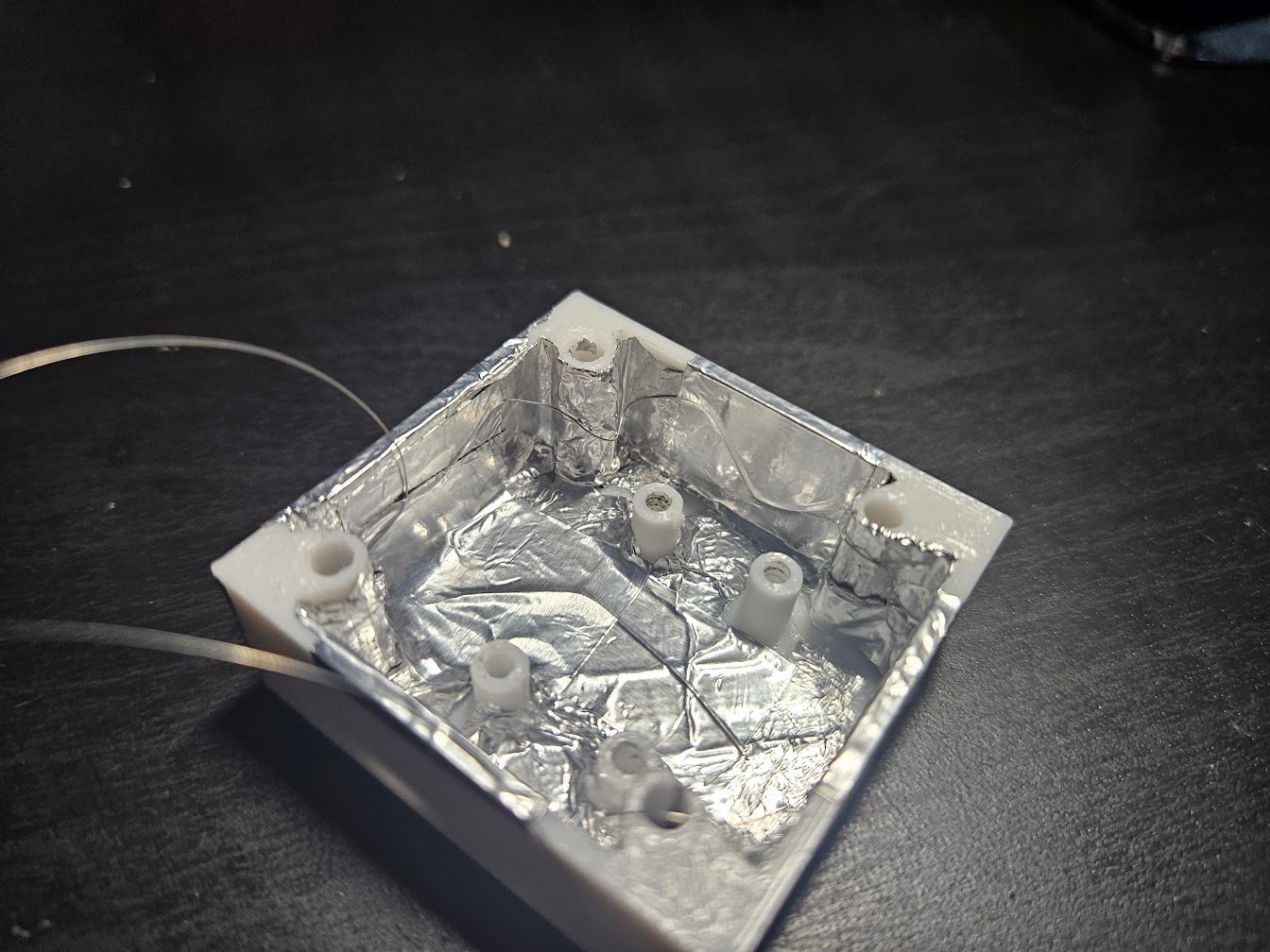
One annoyance about using aluminium tape is that the glue prevents layers of tape from making electrical contact with each other. This means the shielding either has to be one continuous piece of tape, or somehow they need to be connected together.
A good solution I found is to use a very thin wire (I just pulled out a strand from a cable), and zig-zag it around the shielding, taping it down every once in a while to hold it down and force it to make contact with the shielding. This also provides an easy way to connect all the shielding to a grounding point, by just soldering the “leftover” wire. Here are some pictures from shielding a Pi HQ Camera the same way, that show it much better:
VPN
To securely communicate with the server used for video storage, and to remotely access the Pi over SSH, I opted to use OpenVPN.
Basically, there’s a server, and any clients that connect to it will be part of a network, where all the devices can communicate with each other as if they were on a local network. It works just as if there was a new ethernet interface added to each device, and all of those interfaces plugged into a common Ethernet switch.
This is great, because all the encryption and cryptography are handled by OpenVPN, and unsecured connections can be used between all the clients, as if they were on a local network, without having to worry about security. I also won’t need to open any ports for any of the devices, with the exception of a single port on the server, and static IP (or dynamic DNS) is also only required on the server.
To SSH into the Pi, all I’ll have to do is connect to the VPN, and then SSH to the "vpn internal" IP of the Pi.
There are many great guides about setting up an OpenVPN server, they go into much more detail than I have time for in this blog, here is a good one for example:
Along with some extra options and troubleshooting:
https://wiki.archlinux.org/title/OpenVPN
I configured a static IP for each of the devices that will be connecting, by adding this line to each client’s configuration file on the server:
ifconfig-push *ip* *netmask*
(see the Arch Linux wiki for setting up these per-client configuration files)
Now all connected devices can directly reach each other, as if they were on the same local network.
Data Logging
For storing and displaying all sorts of numeric data, I decided on using InfluxDB and Grafana. InfluxDB is a database for storing time-series data, basically just numbers that are logged over time. Grafana is a web UI that can visualize data from many kinds of databases.
The idea is to install InfluxDB both on the Pi and server, and tell the Pi to replicate to the server. InfluxDB should automatically handle synchronization while making sure everything goes smoothly.
I wrote the following code to act as a communications hub for the Pi Pico (see the previous blog post, the short version is that it handles charging mostly):
import zmq
import json
import serial
import threading
import os

# Read serial port and forward to all subscribers
def serial_to_pub():
    ser = serial.Serial('/dev/ttyACM0', 115200)
    context = zmq.Context()
    pub_socket = context.socket(zmq.PUB)
    pub_socket.bind("tcp://*:5050")

    while True:
        line = ser.readline().decode('utf-8').strip()
        try:
            data = json.loads(line)
            pub_socket.send_json(data)
        except json.JSONDecodeError:
            print("Received invalid JSON:", line)

# Take data from clients and forward to serial port
def req_to_serial():
    context = zmq.Context()
    rep_socket = context.socket(zmq.REP)
    rep_socket.bind("tcp://*:5051")

    ser = serial.Serial('/dev/ttyACM0', 115200)

    while True:
        message = rep_socket.recv_string().strip()
        ser.write((message + '\n').encode('utf-8'))
        print("Forwarded to serial:", message)
        rep_socket.send_string("OK")

# Start threads
threading.Thread(target=serial_to_pub).start()
threading.Thread(target=req_to_serial).start()
I am using ZeroMQ for communication between local scripts, here’s a quick overview of the two modes I utilize:
- REQ/REP: There’s a server and a client. A client can send a request to the server, which then has to reply. Exactly one request, then exactly one reply. One server can have many clients connected to it. The server cannot send a message to the client unsolicited.
- PUB/SUB: A server broadcasts data to its clients, no need for requests to reply to.
The PUB/SUB mode is used to broadcast data coming in from the Pi Pico over serial, which is mostly just status reporting from the chargers. Any other script will be able to connect to this ZeroMQ socket, and receive data from the charger.
REQ/REP mode is used for sending data to the Pi Pico. If another script wants to talk to the Pico, it sends a request to the communication hub containing the data to send to the Pico. The communication hub then forwards that to the serial port, and replies back with an “OK”.
For the actual data logging, the following code handles writing data to InfluxDB from various sources. The first one is the ZeroMQ socket where the charger data is available from, the second one is GPSD.
import influxdb_client
from influxdb_client.client.write_api import ASYNCHRONOUS, SYNCHRONOUS
import json
import zmq
import time
import gps
import queue
import threading

GPS_STANDBY_WRITE_INTERVAL_SECS = 5
GPS_ACTIVE_WRITE_INTERVAL_SECS = 1
CHG_STANDBY_WRITE_INTERVAL_SECS = 10
CHG_ACTIVE_WRITE_INTERVAL_SECS = 5

MAX_WRITE_BATCH = 20

API_TOKEN="token"
client = influxdb_client.InfluxDBClient(url="127.0.0.1:8086", token=API_TOKEN, org="org")
write_api = client.write_api(write_options=SYNCHRONOUS)
point_queue = queue.Queue()
gps_write_interval_secs = 5
chg_write_interval_secs = 10

gps_last_write_time = 0
def gps_thread():
    global gps_last_write_time

    session = gps.gps(mode=gps.WATCH_ENABLE)
    while 0 == session.read():
        try:
            if not (gps.MODE_SET & session.valid):
                continue

            if time.time() - gps_last_write_time < gps_write_interval_secs:
                continue
            gps_last_write_time = time.time()

            point = influxdb_client.Point("gps")

            if gps.isfinite(session.fix.latitude) and gps.isfinite(session.fix.longitude):
                point = point.field("latitude", session.fix.latitude).field("longitude", session.fix.longitude)

            if gps.isfinite(session.fix.speed):
                point = point.field("speed", session.fix.speed)

            if gps.isfinite(session.fix.altMSL):
                point = point.field("altitude", session.fix.altMSL)

            if gps.isfinite(session.fix.mode):
                point = point.field("fixType", session.fix.mode)

            if gps.isfinite(session.fix.track):
                point = point.field("track", session.fix.track)

            if gps.isfinite(session.fix.epd):
                point = point.field("track_error", session.fix.epd)

            if gps.isfinite(session.fix.eps):
                point = point.field("speed_error", session.fix.eps)

            if gps.isfinite(session.fix.epx):
                point = point.field("latitude_error", session.fix.epx)

            if gps.isfinite(session.fix.epy):
                point = point.field("longitude_error", session.fix.epy)

            if gps.isfinite(session.fix.epv):
                point = point.field("altitude_error", session.fix.epv)

            point_queue.put(point)

        except Exception as e:
            print(f"Failed to get GPS data: {e}")
            continue


zmq_last_write_time = 0
def zmq_thread():
    global zmq_last_write_time
    global chg_write_interval_secs
    global gps_write_interval_secs
    # Set up ZMQ
    context = zmq.Context()
    sub_socket = context.socket(zmq.SUB)
    sub_socket.connect("tcp://localhost:5050")
    sub_socket.setsockopt_string(zmq.SUBSCRIBE, "")  # Subscribe to all messages

    while True:
        try:
            # Check for messages from the MCU
            line = sub_socket.recv_string().strip()

            # Skip writing to try and keep up write_interval_secs rate
            if time.time() - zmq_last_write_time < chg_write_interval_secs:
                continue
            zmq_last_write_time = time.time()

            data = json.loads(line)
            chargers = data.get("chargers", [])
            charger_points = []
            for charger in chargers:
                id = f"bq{charger['id']}"
                inputVoltage = float(charger.get("inputVoltage"))
                inputCurrent = float(charger.get("inputCurrent"))
                batteryVoltage = float(charger.get("batteryVoltage"))
                chargeCurrent = float(charger.get("chargeCurrent"))
                temperature = float(charger.get("temperature"))

                if batteryVoltage > 10:
                    chg_write_interval_secs = CHG_ACTIVE_WRITE_INTERVAL_SECS
                    gps_write_interval_secs = GPS_ACTIVE_WRITE_INTERVAL_SECS
                else:
                    chg_write_interval_secs = CHG_STANDBY_WRITE_INTERVAL_SECS
                    gps_write_interval_secs = GPS_STANDBY_WRITE_INTERVAL_SECS

                charger_points.append(
                    influxdb_client.Point(id)
                    .field("inputVoltage", inputVoltage)
                    .field("inputCurrent", inputCurrent)
                    .field("batteryVoltage", batteryVoltage)
                    .field("chargeCurrent", chargeCurrent)
                    .field("temperature", temperature)
                )

            battery = data.get("battery", {})
            batteryVoltage = float(battery.get("voltage"))
            batteryCurrent = float(battery.get("current"))
            batteryWh = float(battery.get("remainingWh"))

            battery_points = [
                influxdb_client.Point("battery")
                .field("voltage", batteryVoltage)
                .field("current", batteryCurrent)
                .field("remainingWh", batteryWh)
            ]

            generatorVoltage = float(data.get("generatorVoltage"))
            fanSpeed = int(data.get("fanSpeed"))
            forceBackup = bool(data.get("forceBackupCharging"))

            misc_points = [
                influxdb_client.Point("misc")
                .field("generatorVoltage", generatorVoltage)
                .field("fanSpeed", fanSpeed)
                .field("forceBackupCharging", forceBackup)
            ]

            all_points = charger_points + battery_points + misc_points
            for point in all_points:
                point_queue.put(point)
        except Exception as e:
            print(f"Failed to fetch ZMQ data: {e}")
            continue

if __name__ == "__main__":
    gps_thread = threading.Thread(target=gps_thread)
    gps_thread.start()

    zmq_thread = threading.Thread(target=zmq_thread)
    zmq_thread.start()

    while True:
        try:
            write_api.write(bucket="mvpp", org="org", record=point_queue.get())
        except Exception as e:
            print(f"Failed to get/write point: {e}")
            continue
The logging interval depends on the car generator voltage measured by the Pi Pico, as there is no need for frequent data logging when the car is parked.
Grafana
Grafana is a web UI used for visualizing information from databases. The basic idea is to pick a visualization type, like a line chart or bar graph, and write a query, and the returned data will be displayed (with some extra configuration usually required, to make sure everything looks nice). These visualizations then can be added to a “Dashboard”.
After spending some time configuring charts and writing queries, I ended up with this dashboard:
The dashboards can also be set up to auto update as often as once every 5 seconds, and many other types of visualizations are also available, so Grafana is suitable for live monitoring too, not just browsing historical data.
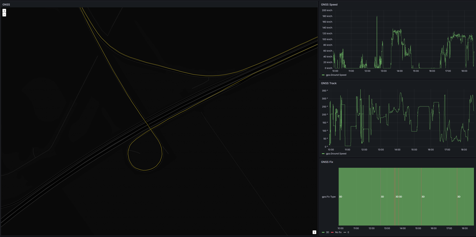
Here’s some data from the GPS:
Setting up replication to the remote server was relatively easy, just had to create an API key on the server with write permissions, and configure InfluxDB on the Pi to replicate to the database on the server, while giving it the API key generated earlier.
InfluxDB has some issues unfortunately, one of them being that replication takes forever if datapoints are written one-by-one on the Pi, instead of in groups.
It seems like replication is just "replaying" the data insertion requests as they came in originally, instead of grouping a bunch of them into a single request. This is the reason for collecting all the datapoints into one big list, and writing them at once in the logging python script. This puts many values in a single request (which would be irrelevant between the python script and local InfluxDB database as bandwidth between local processes is essentially unlimited) and therefore speeds up replication to the remote server significantly.
Video Streaming
After doing some research, I couldn’t find any suitable way of streaming video from the Pi to the server with minimal latency, while also being able to handle the random dropouts and slowdowns of the 4G network connection, so I started making my own.
I used ZeroMQ for this as well, in the REQ/REP mode. The Pi sends a chunk to the server, the server replies if everything arrived correctly. If not, the chunk is sent again.
For now, I’m using a Pi HQ camera, compressing the video stream with H264 utilizing the hardware encoder of the Pi4, putting the encoded video chunks into a deque (double ended queue, a doubly linked list basically) at one end, and taking the chunks out at the other end to send to the server. If successfully transferred, the chunk is deleted from the deque.
A deque is great for this, because it doesn’t need continuous memory and therefore doesn't require reallocation. Each element can be allocated anywhere in memory, with no regard to order either, and each element stores a pointer to the previous and next elements. Whenever adding an element, just allocate it anywhere, update the previous element’s “next” pointer to point to this new element, and set the new element’s “prev” pointer to point to the previous element. This is better than a regular linked list, because it can be traversed in both directions instead of just forward, while having basically no overhead (well, 8 bytes per element).
If network conditions are good, the deque will almost always be empty, since every chunk put in at the beginning will be immediately taken out and transferred to the server. If network conditions deteriorate, syncing might slow down, and the deque begins to grow. As sync speeds improve, the built-up data is synced to the server oldest-first.
I set a limit of 512MB for the deque size, which can fit roughly 12 minutes of video in case there’s no internet connection at all. In the future, I’m planning to implement a feature to start saving this video to an external SSD, and sync it to the server later, but for now, the end of the deque gets discarded if it grows past 512MB.
The H264 encode bitrate is adjusted based on generator voltage(which depends on whether the engine is running or not), like with the charger logging interval. I’ve settled on 6Mbps when driving, 1Mbps when parked.
Deque size and average sync speed are also logged to InfluxDB.
To ensure chunks are successfully transmitted, each chunk of data is SHA256 hashed, and the last 4 bytes of this hash is appended to the data. The receiver will use this to verify that everything arrived correctly.
This is the sender part:
import io, time, zmq, collections, hashlib, threading, struct
from typing import Deque

MAX_BUF_SIZE = 512_000_000 # 512MB


class SyncbufSource(io.BufferedIOBase):
    bytes_buffer: Deque[bytes] = collections.deque()
    server_address = None
    zmq_context = None
    zmq_socket = None
    sync_thread = None
    sync_thread_run = True
    write_callback = None
    sync_callback = None
    transmit_id: int = 0

    def __init__(self, server_address, write_callback = None, sync_callback = None):
        # Socket initialization
        self.zmq_context = zmq.Context()
        self.server_address = server_address

        # Sync thread initialization
        self.sync_thread_run = True
        self.sync_thread = threading.Thread(target=self.sync_loop)
        self.sync_thread.setDaemon(True)
        self.sync_thread.start()

        self.write_callback = write_callback
        self.sync_callback = sync_callback

    def buffer_size(self):
        byte_count = 0
        buf_len = len(self.bytes_buffer)
        try:
            for i in range(buf_len):
                byte_count += len(self.bytes_buffer[i])
        except IndexError:
            pass
        return byte_count

    def stop_sync(self):
        self.sync_thread_run = False
        self.sync_thread.join()

    def start_sync(self):
        self.sync_thread_run = True
        self.sync_thread = threading.Thread(target=self.sync_loop)
        self.sync_thread.start()

    def write(self, buf: bytes):
        self.bytes_buffer.append(buf)
        if self.write_callback:
            self.write_callback(len(buf))
        #print(f"Wrote {len(buf)} bytes to buffer, buf len: {len(self.bytes_buffer)}, total size: {self.buffer_size()} bytes")

    def trim_buffer(self):
        while self.buffer_size() > MAX_BUF_SIZE:
            trimmed_size = len(self.bytes_buffer.popleft())
            print(f"Trimmed {trimmed_size} bytes from buffer")

    def init_zmq(self):
        self.zmq_socket = self.zmq_context.socket(zmq.REQ)
        self.zmq_socket.connect(self.server_address)
        self.zmq_socket.setsockopt(zmq.SNDTIMEO, 0)
        self.zmq_socket.setsockopt(zmq.LINGER, 0)

    def get_buffer_stats(self):
        return {
            "buffer_size": self.buffer_size(),
            "buffer_len": len(self.bytes_buffer)
        }

    def zmq_socket_reset(self):
        self.zmq_socket.setsockopt(zmq.LINGER, 0)
        self.zmq_socket.close()
        self.init_zmq()

    def zmq_reliable_communicate(self, message):
        # Initialize socket if not already initialized
        if not self.zmq_socket:
            self.init_zmq()

        # Send message and save start time
        self.zmq_socket.send(message)
        start_time = time.time()

        while True:
            # Check if response is available, blocks for 1 second max
            if self.zmq_socket.poll(1000) & zmq.POLLIN != 0:
                return self.zmq_socket.recv()

            # If still no response after 10 seconds, reset and reconnect socket
            if start_time + 10 < time.time():
                self.trim_buffer() # Since the most likely scenario for buffer growing too big is a disconnected socket, we should do this here too
                print("No ZMQ response received after 10 seconds, resetting socket")
                self.zmq_socket_reset()

                # Try sending message again
                self.zmq_socket.send(message)
                start_time = time.time()


    def sync_loop(self, target_size: int = 128_000, min_size: int = 16_000):
        while self.sync_thread_run:
            # Nothing to sync
            if not self.bytes_buffer:
                time.sleep(0.05)
                continue

            # Only sync if there's at least min_size bytes in buffer
            if self.buffer_size() < min_size:
                time.sleep(0.05)
                continue

            self.trim_buffer()

            # Gather chunks to send to server, until target_size is reached at maximum
            transmit_id_bytes = struct.pack('<I', self.transmit_id)
            chunks = bytearray(transmit_id_bytes)
            while self.bytes_buffer:
                new_chunk = self.bytes_buffer.popleft()
                chunks.extend(new_chunk)
                if(len(chunks) >= target_size):
                    break

            # Append sha256 hash of chunks to the end of chunks
            sha = hashlib.sha256()
            sha.update(chunks)
            digest = sha.digest()
            chunks.extend(digest[:4]) # First 32bits of sha256 hash is more than enough

            # Continuously try sending chunks to server until sent successfully
            while True:
                resp = self.zmq_reliable_communicate(chunks)

                # Check for length
                if len(resp) != 4:
                    print(f"Invalid response length: {len(resp)}")
                    continue

                # Magic bytes for mismatching hash(should never happen)
                if resp == b'\xFF\xFF\xFF\xFF':
                    print("Server received mismatching hash")
                    continue

                # Check if sequence number is correct
                receive_id = struct.unpack('<I', resp[:4])[0]
                if receive_id != self.transmit_id:
                    print(f"Transmit ID and Receive ID mismatch. Transmit ID: {self.transmit_id}, Receive ID: {receive_id}")
                    continue

                # Everything looks in order
                else:
                    break

            self.transmit_id += 1

            if self.sync_callback:
                self.sync_callback(len(chunks) - 4)

    def detect_nal_units(self, buf: bytes):
        start_code_1 = b'\x00\x00\x01'
        start_code_2 = b'\x00\x00\x00\x01'
        start_codes = [start_code_1, start_code_2]

        start = 0
        while start < len(buf):
            for start_code in start_codes:
                start_pos = buf.find(start_code, start)
                if start_pos != -1:
                    # Find end of NAL unit
                    next_start_pos = len(buf)
                    for next_start_code in start_codes:
                        next_start_pos = buf.find(next_start_code, start_pos + len(start_code))
                        if next_start_pos != -1:
                            break

                    # Calculate NAL unit size
                    if next_start_pos == -1:
                        nal_unit_size = len(buf) - start_pos - len(start_code)
                    else:
                        nal_unit_size = next_start_pos - start_pos - len(start_code)

                    nal_unit_type = buf[start_pos + len(start_code)] & 0x1F
                    print(f"Found NAL unit type: {nal_unit_type}, Size: {nal_unit_size} bytes")

                    start = start_pos + len(start_code)
                    break
            else:
                break
It can be used with anything that tries to write to a file-like object, for example picamera2's capture functions. Here's the code handling video capture, streaming to the server, and logging related parameters to InfluxDB:
from picamera2 import Picamera2
from picamera2.encoders import H264Encoder, Quality
from picamera2.outputs import FileOutput
from libcamera import Transform, controls
import time
from syncbuf_source import SyncbufSource
import signal
import sys
import zmq
import json
import influxdb_client
import collections
from influxdb_client.client.write_api import ASYNCHRONOUS, SYNCHRONOUS
from typing import Deque

DB_LOG_INTERVAL = 5
STATUS_PRINT_INTERVAL = 30
SYNC_SPEED_AVG_WINDOW_SECS = 10
API_TOKEN="token"

def signal_handler(sig, frame):
    print("Stopping camera")
    picam2.stop()
    picam2.stop_encoder()
    print("Exiting")
    sys.exit(0)
signal.signal(signal.SIGINT, signal_handler)

# Keep track of the last time picamera gave us data
last_write = time.time()
def write_callback(write_size):
    global last_write
    if write_size > 0:
        last_write = time.time()

# Measure sync speed
sync_stats = collections.deque()
def sync_callback(synced_bytes):
    sync_stats.append((time.time(), synced_bytes))

tuning = Picamera2.load_tuning_file("imx477.json")
algo = Picamera2.find_tuning_algo(tuning, "rpi.agc")

for x in range(len(algo["channels"])):
    algo["channels"][x]["metering_modes"]["custom"] = {"weights": [1,1,1,0,1,1,1,1,1,0,1,0,0,1,1]}

picam2 = Picamera2(tuning=tuning)

config = picam2.create_video_configuration(
    raw = None,
    lores = None,
    main = {
        "size": (1440, 1080)
    },
    buffer_count = 8,
    transform=Transform(hflip=True, vflip=True)
)

picam2.align_configuration(config)
picam2.configure(config)
picam2.set_controls({"FrameDurationLimits": (62_500, 62_500)}) # 16 FPS default
picam2.set_controls({"AeMeteringMode": controls.AeMeteringModeEnum.Custom})

print(picam2.controls)

syncbuf = SyncbufSource("tcp://10.255.3.2:5555", write_callback=write_callback, sync_callback=sync_callback)
output = FileOutput(syncbuf)
encoder = H264Encoder(repeat=True, iperiod=8, enable_sps_framerate=True, framerate=16, bitrate=6_000_000)
picam2.start_encoder(encoder, output)
picam2.start()

context = zmq.Context()
sub_socket = context.socket(zmq.SUB)
sub_socket.connect("tcp://localhost:5050")
sub_socket.setsockopt_string(zmq.SUBSCRIBE, "")  # Subscribe to all messages

client = influxdb_client.InfluxDBClient(url="127.0.0.1:8086", token=API_TOKEN, org="org")
write_api = client.write_api(write_options=ASYNCHRONOUS)

hq_mode = True # Whether we are running in high-FPS high-bitrate mode, or low-FPS low-bitrate mode

time.sleep(1) # Don't immediately switch from high to low bitrate mode if the generator voltage is low on startup

db_log_timer = time.time()
status_print_timer = time.time()

while True:
    try: # This is ugly, but this loop really shouldn't crash. The main priority is to keep the camera running in the thread managed by picamera2, and crashing the main loop will stop the picamera2 thread.
        time.sleep(0.05)
        # Check for messages from the MCU
        if sub_socket.poll(0) & zmq.POLLIN != 0:
            line = sub_socket.recv_string().strip()
            try:
                data = json.loads(line)
                generatorVoltage = float(data.get("generatorVoltage"))

                if generatorVoltage < 10 and hq_mode:
                    print("Switching to low bitrate mode")
                    hq_mode = False
                    picam2.stop()
                    picam2.stop_encoder()
                    encoder = H264Encoder(repeat=True, iperiod=8, enable_sps_framerate=True, framerate=4, bitrate=1_000_000)
                    picam2.set_controls({"FrameDurationLimits": (250_000, 250_000)}) # 4 FPS
                    picam2.start_encoder(encoder, output)
                    picam2.start()

                if generatorVoltage >= 10 and not hq_mode:
                    print("Switching to high bitrate mode")
                    hq_mode = True
                    picam2.stop()
                    picam2.stop_encoder()
                    encoder = H264Encoder(repeat=True, iperiod=8, enable_sps_framerate=True, framerate=16, bitrate=6_000_000)
                    picam2.set_controls({"FrameDurationLimits": (62_500, 62_500)}) # 16 FPS
                    picam2.start_encoder(encoder, output)
                    picam2.start()

            except json.JSONDecodeError:
                print("Failed to decode JSON")
                continue

        if last_write + 10 < time.time():
            print("Camera has stopped writing data, attempting restart")
            picam2.stop()
            picam2.stop_encoder()
            time.sleep(1)
            picam2.start_encoder(encoder, output)
            picam2.start()
            last_write = time.time()

        if db_log_timer + DB_LOG_INTERVAL < time.time():
            db_log_timer = time.time()

            # Calculate average sync speed in the last 5 seconds
            # Remove stats older than 5 seconds
            threshold = time.time() - SYNC_SPEED_AVG_WINDOW_SECS
            while sync_stats and sync_stats[0][0] < threshold:
                sync_stats.popleft()

            # Sum up transferred bytes
            transferred_bytes = 0
            stat_count = len(sync_stats)
            for x in range(stat_count):
                transferred_bytes += sync_stats[x][1]

            # Calculate average sync speed
            transferred_bytes /= SYNC_SPEED_AVG_WINDOW_SECS

            # Log buffer stats
            buf_stats = syncbuf.get_buffer_stats()

            points = [
                influxdb_client.Point("misc")
                .field("bufferSize", buf_stats['buffer_size'])
                .field("bufferCount", buf_stats['buffer_len'])
                .field("syncSpeed", transferred_bytes)
            ]
            write_api.write(bucket="mvpp", org="org", record=points)

        if status_print_timer + STATUS_PRINT_INTERVAL < time.time():
            status_print_timer = time.time()

            buf_stats = syncbuf.get_buffer_stats()
            print(f"Buffer length: {buf_stats['buffer_len']}, total size: {buf_stats['buffer_size']} bytes")
    except Exception as e:
        print(f"Main loop exception: {e}")
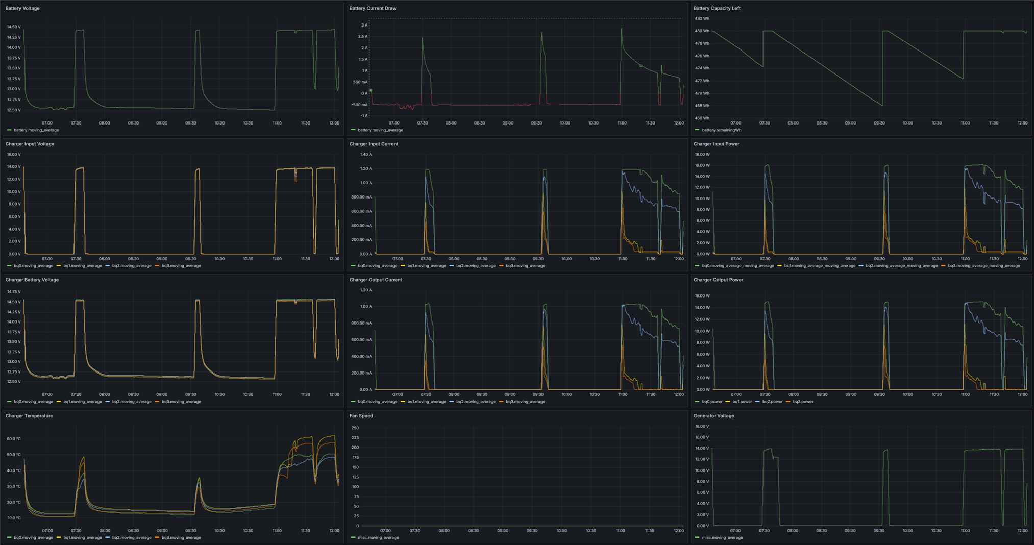
With all of this data logged, I’ve put together another Grafana dashboard, made for real-time monitoring:

The dashboard can be set to auto-update, with the default configuration allowing 5 seconds per refresh at the fastest.
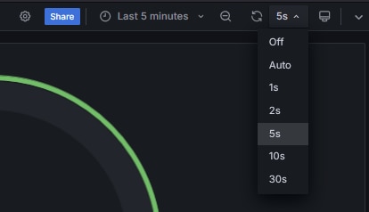
By setting min_refresh_interval in the Grafana configuration file, this can be overridden to be more frequent. After restarting Grafana, in the dashboard settings, add new custom values for "Auto Refresh", and afterwards they will be visible in the drop-down box in the top right:
Receiving Video
Receiving the video stream on the server is quite simple, just receive from the ZeroMQ socket, extract the checksum in the last 4 bytes of the data, hash the rest, compare with the extracted checksum, and reply back to the sender, either confirming a successful transfer, or asking for a resend. A sequence number is also used so out-of-order transfers can be detected (although in the current implementation, they are impossible, since a new chunk is only sent once the previous one arrived successfully).
import zmq
import hashlib
import struct
import datetime

FILE_SIZE_SPLIT = 100_000_000 # 100MB

context = zmq.Context()
socket = context.socket(zmq.REP)
socket.bind("tcp://*:5555")

current_time = datetime.datetime.now().strftime("%Y-%m-%d_%H-%M-%S")
file = open(f"output_{current_time}.h264", "wb")
file_size = 0
wait_count = 0

while True:
    if socket.poll(1000, zmq.POLLIN) != 0:
        wait_count = 0
        message = socket.recv()

        if message == b'ping':
            socket.send(b'pong')
            print("Received ping, sent pong")
            continue

        checksum = message[-4:]
        sequence_raw = message[:4]
        sequence = struct.unpack('<I', sequence_raw)[0]

        payload = message[4:-4]

        print(f"Received seq {sequence} with checksum {checksum.hex()}, {len(message)} bytes")

        sha = hashlib.sha256()
        sha.update(message[:-4])
        digest = sha.digest()

        if digest[:4] != checksum:
            print(f"Checksum mismatch for frame {sequence}, expected {checksum.hex()} but got {digest.hex()}")
            socket.send(b'\xFF\xFF\xFF\xFF')
        else:
            socket.send(sequence_raw)
            file.write(payload)
            file_size += len(payload)
            if(file_size >= FILE_SIZE_SPLIT):
                print(f"Splitting file, size {file_size} bytes")
                file.close()
                current_time = datetime.datetime.now().strftime("%Y-%m-%d_%H-%M-%S")
                file = open(f"output_{current_time}.h264", "wb")
                file_size = 0
    else:
        print("Waiting for message...")
        wait_count += 1
        if wait_count > 10 and file_size > 0:
            print(f"Splitting file, size {file_size} bytes")
            file.close()
            current_time = datetime.datetime.now().strftime("%Y-%m-%d_%H-%M-%S")
            file = open(f"output_{current_time}.h264", "wb")
            file_size = 0
            wait_count = 0
The stream is written into .h264 files, split into 100MB chunks to be more easily manageable. A tool like ffmpeg can be used to convert these .h264 files into more common formats later.
Canbus
I decided to hook up the two canbus networks in my car to the Pi, to allow me to access information like vehicle speed and engine parameters.
The board I used is a Waveshare 2-CH CAN HAT, and it uses two MCP2515 SPI canbus controllers, along with two SN65HVD230 transceivers. The transceiver side is fully isolated, which is nice, although not useful in my case.
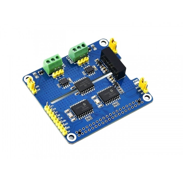
I did not want to use the board as a HAT, as I'd have to redesign a lot of already existing hardware, so I decided to make it an external box, much like how the 4G/GPS module is done.
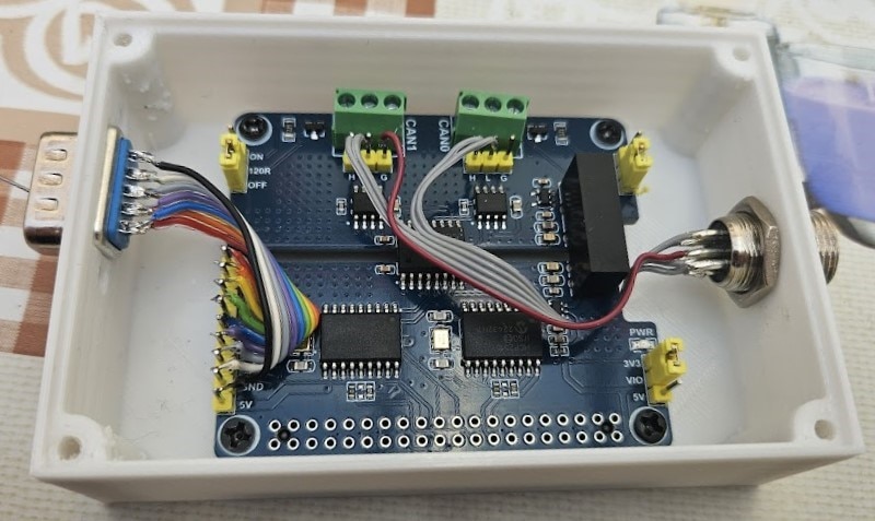
A DB9 connector is used for power + SPI + two chip select signals + two interrupts, and a GX12 6-pin connector for the 2 pairs of canbus signals along with ground. A custom cable connects to the GX12 connector, that has an OBD2 plug on the other end.
I added the corresponding DB9 connector on the Raspberry Pi side, making an even larger mess with the wiring now. The fan has also been upgraded, to a quieter model that supports a PWM input for speed control, and I also replaced one of the barrel jack charger inputs with a GX20 two pin connector for higher power charging since the last blog.
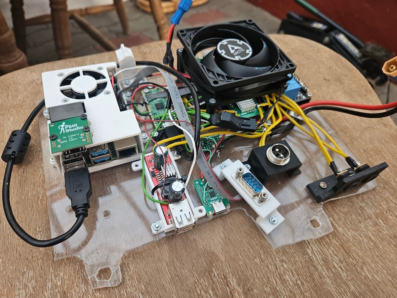
A custom PCB would’ve made this look much more professional while occupying significantly less space, but at this point I’m constantly changing things around, and this approach gives me the flexibility to swap parts around quickly without having to redo everything.
Both the canbus and 4G modules hooked up:
Setting up the canbus interface on the Pi was really simple, all I had to do was add two lines to config.txt to load and configure the mcp2515 device tree overlay.
dtoverlay=mcp2515-can1,oscillator=16000000,interrupt=24
dtoverlay=mcp2515-can0,oscillator=16000000,interrupt=23
After a reboot, a can0 and can1 interface appeared. To initialize the interfaces at the correct bitrate, I used these commands:
sudo ip link set can0 up type can bitrate 50000 listen-only on
sudo ip link set can1 up type can bitrate 500000 listen-only on
Using cansniffer, it is now possible to see all the canbus messages the car is using to communicate, all that’s left is to figure out which message contains what data.
This is what the output looks like while driving around:
I haven’t had time to decipher all of the messages yet, but when I’m done with them, I’ll write a python script that parses and exposes the values on a ZeroMQ pub/sub socket similar to the communications hub script shown before, and update the InfluxDB logging script to also write these values to the database.
Conclusion
With most of the sensors and data synchronization now functional, the largest remaining task is setting up the Arty-Z7 to do object recognition, connected to the Raspberry Pi over ethernet, and set up a display with a user interface.

