Overview
To power all the electronics when the car is not running, there’s a need for some sort of energy storage system. When the car is running, the batteries are charged from the generator of the vehicle. In case of extended periods of time parked, I also need a way to charge from other sources, like a second battery, or solar panels.
The Batteries
The first type of battery that comes to mind is lithium-ion, but I don’t want my car to explode in sunlight, so that’s not going to work.
Luckily, weight and space isn’t a huge concern, so lead-acid batteries will be used.
An even better solution would be LiFePo4, but they are significantly more expensive and harder to obtain than lead-acid.
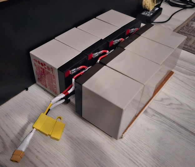
I managed to salvage 8x 12V 5Ah AGM batteries from an old UPS, they seem to be in okay condition for this project.
First step was figuring out what topology to connect the batteries in. The car’s generator supplies somewhere between 12.5 to 14.5 volts, and I knew I wanted to use BQ25798 ICs for charging. I found these efficiency curves in the datasheet:
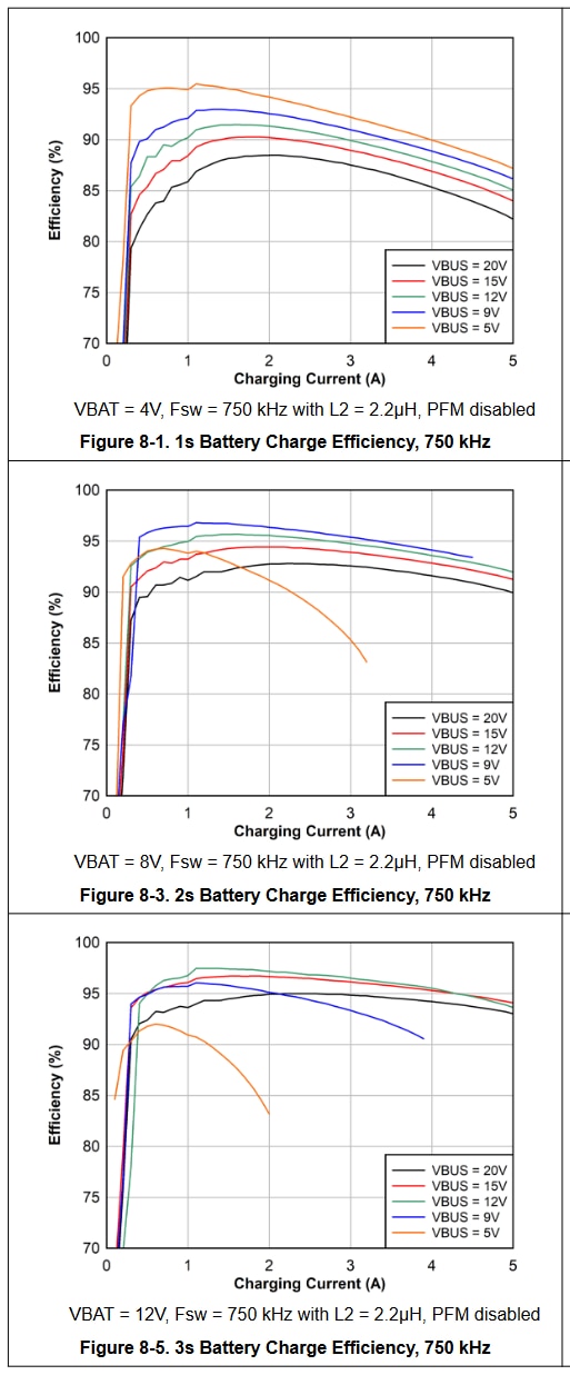
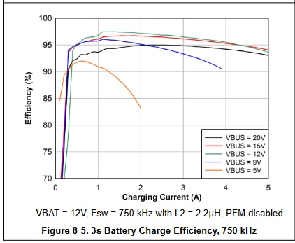
It looks like the most efficient way of charging is to use buck converter mode, and to keep the input voltage slightly above the output voltage. To do this, I ended up connecting all the batteries in parallel.
(also, the BQ25798 cannot do more than about 20V output, so I didn’t really have a choice with the topology)
This pack also fits perfectly under the front passenger seat, so it is completely invisible, and doesn’t take up any useful space in the car.
Charging ICs
As mentioned before, I wanted to use the BQ25798, as I’ve already tested these in one of my previous projects (link here), and really liked them. They take 3.6 to 24V input, 5A maximum output current, buck-boost, MPPT capable, have an integrated ADC that can measure both input and output voltage and current, and can officially charge 1-4 Li-ion cells. However, all charging stages are completely configurable over I2C, so by changing some settings, I got them to work well for charging lead-acid batteries too.
The only issue is the maximum output current, which is supposed to be 5A, but is more like 3.5A, due to the horrible package TI decided to use. There’s simply not enough surface area to transfer the heat out from the IC, so even in the most optimal setup, I wasn’t able to get more than 4A out of it without overheating.
To solve this problem, I just decided to get 4 of them to use in parallel, for a max charging current of about 14A, or increased efficiency when charging at lower currents. For example, charging at 4A with a single one would result in an efficiency of about 95%, while using 3 of them at 1.33A each would achieve roughly 97.5%, halving losses, and spreading heat out over a larger area.
For now, I’ve decided on making small, separate “breakout” style PCBs instead of a monolithic one, so I can swap components easier later, and make all the parts I use in this project reusable later.
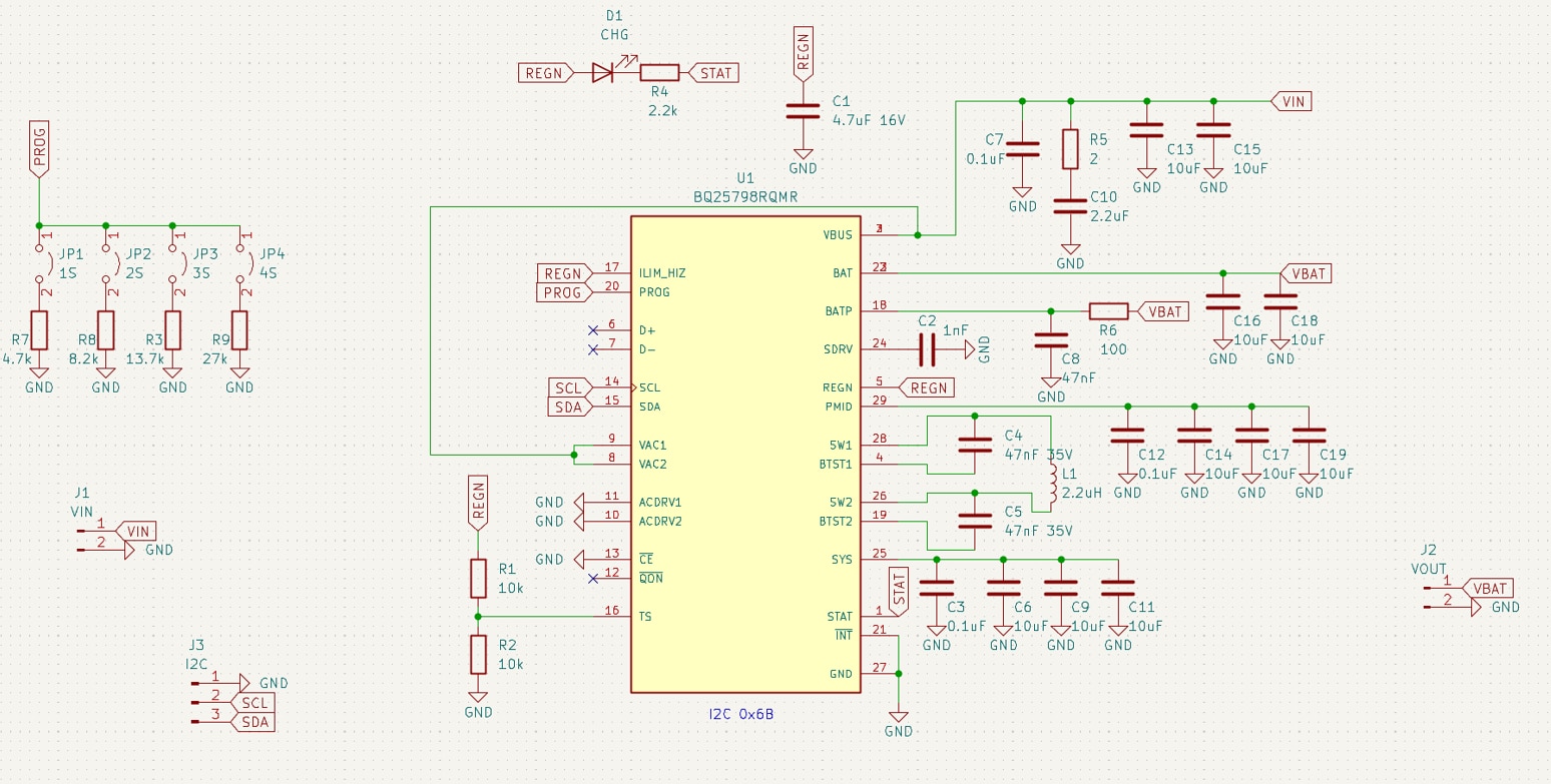
One very important detail here: I did not populate the two resistors that emulate a temperature sensor. I’ll go into details later, but the short version is that the charger would try to charge the batteries to 16.8V with them present, while the recommended charge voltage for my batteries is around 14.4-14.6V. Needless to say, that would result in a very sad day, both for me and the batteries.
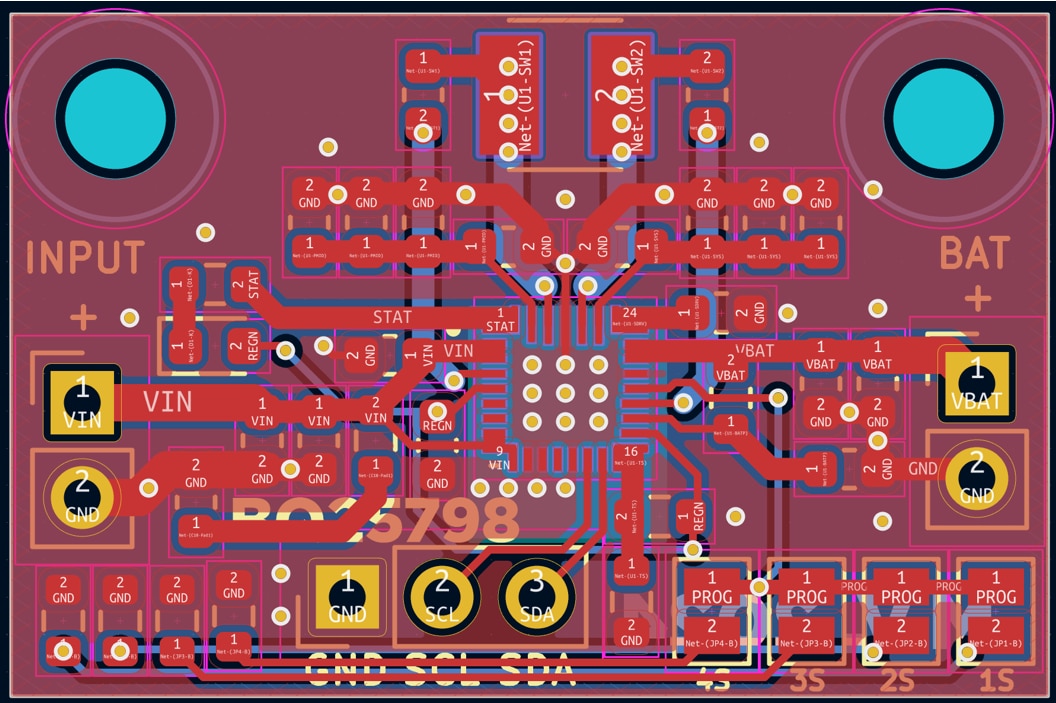
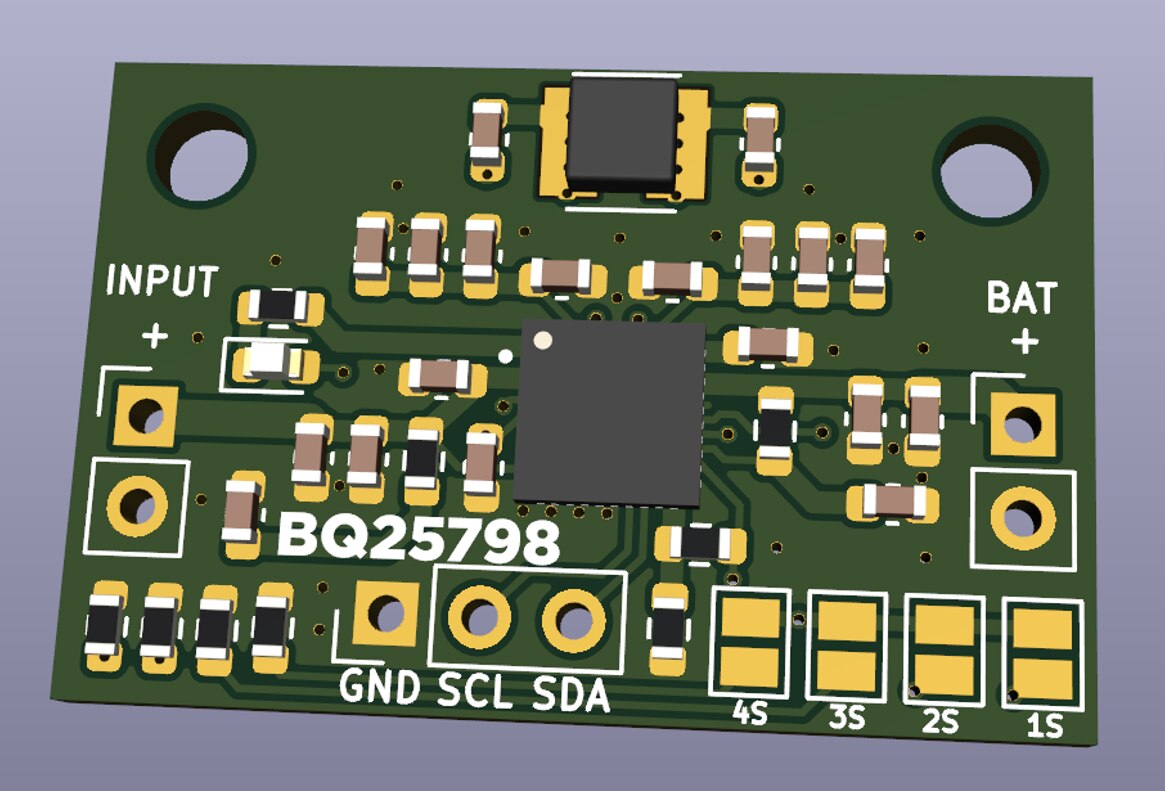
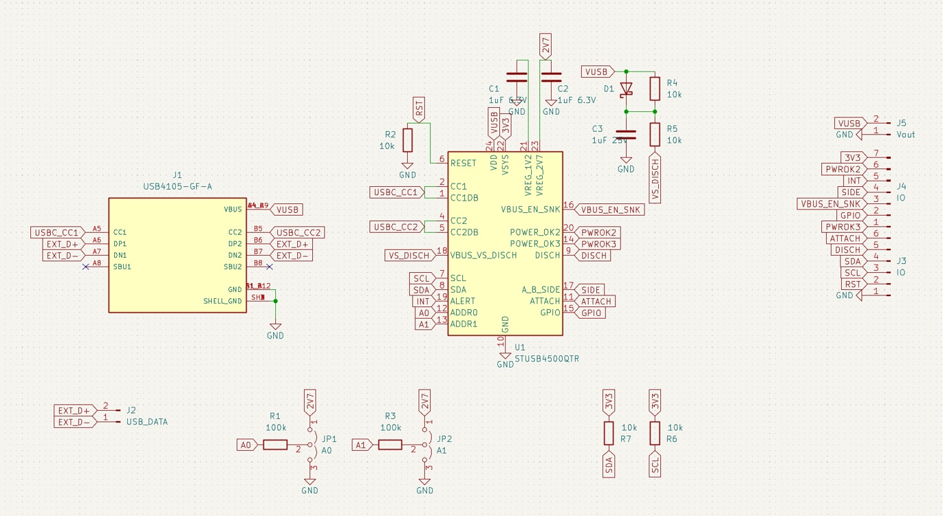
I also designed two more breakout boards:
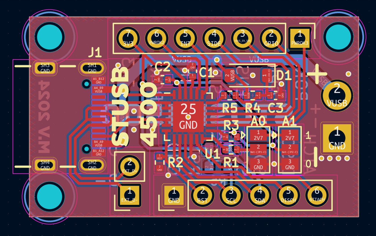
One for the STUSB4500, which is a USB-PD sink controller. Basically, it lets me request up to 20V through USB-C. I wanted to be able to use USB-PD power banks to charge the lead-acid pack in case the car is left parked for a long time in public areas.
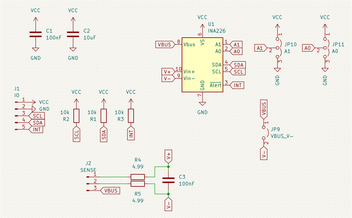
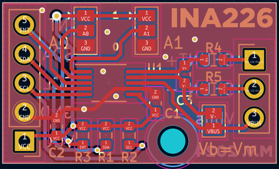
The third design is an INA226 breakout board, which is an I2C voltage and current sensor.
I also made a breakout board for the MAX17261, but that’s for a different project.
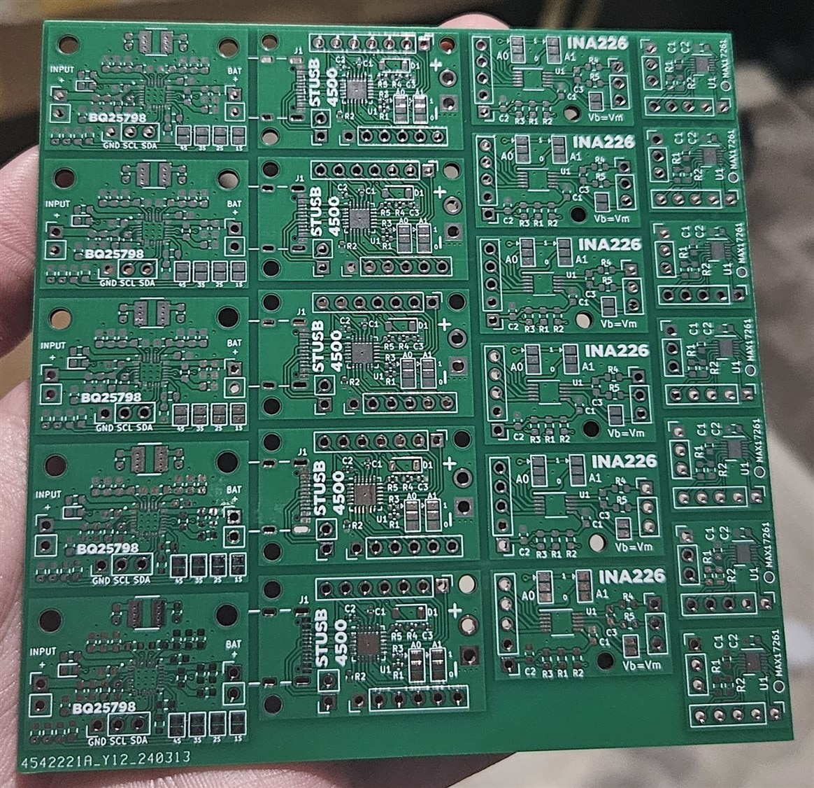
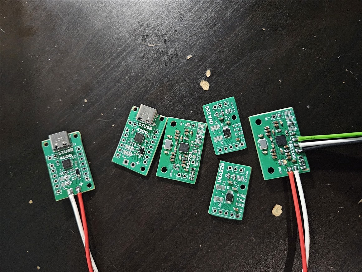

I only realized after testing them that the I2C address cannot be changed, and the Raspberry Pi Pico I wanted to use only has 2 I2C buses. The solution was to buy an I2C mux board, that “splits” one I2C bus into 8, and the master can select which one to “talk” to, by setting a register.
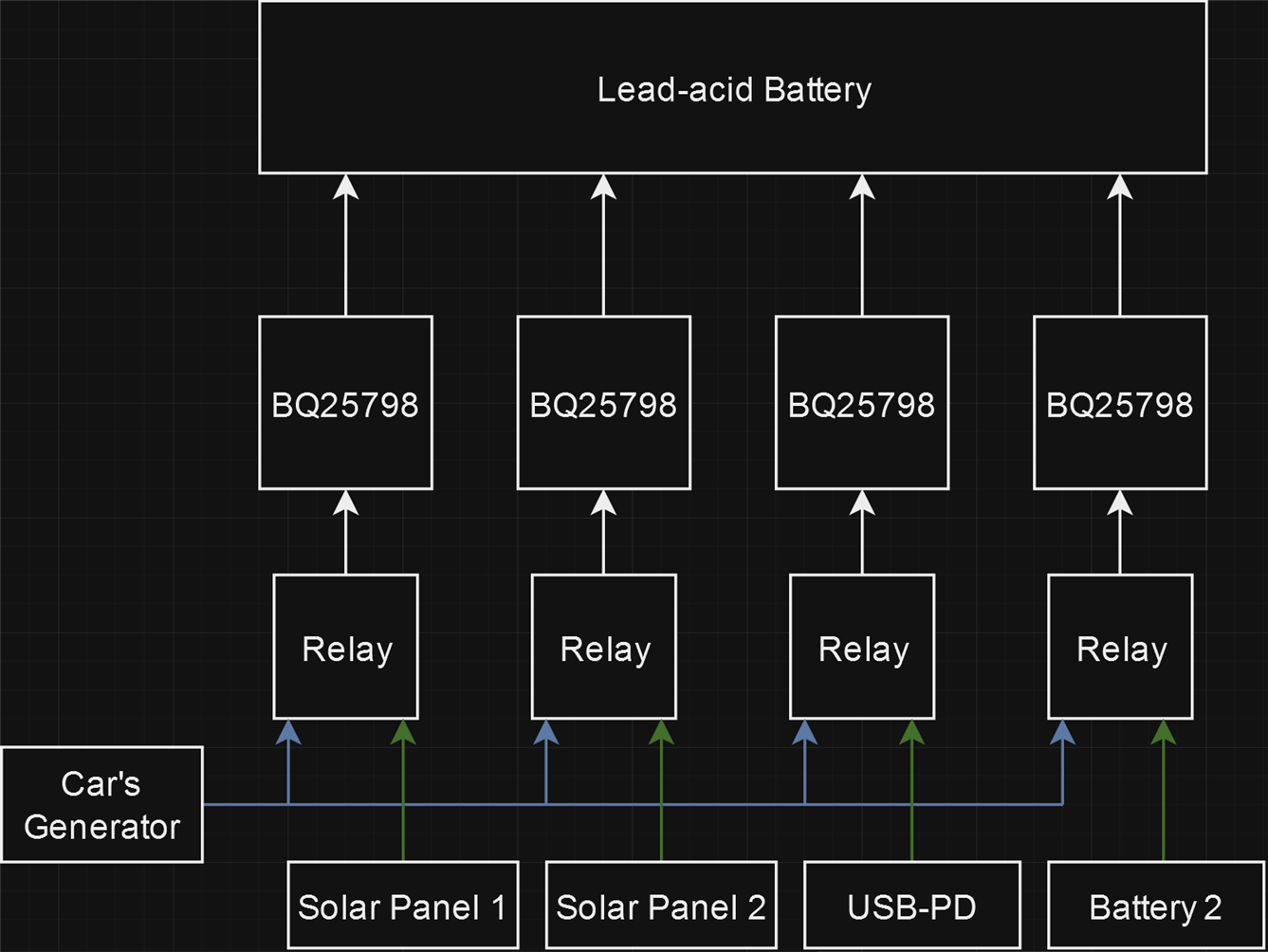
I also decided to add a relay at the input of each BQ25798, so I could choose from two input sources for charging. One of the inputs on each charger will be connected to the car’s generator, so the batteries can charge while the car is running, while the other input on each charger will each serve different purposes. The first two chargers will have the option to use a solar panel as an input power source, the third charger will be for USB-C charging, and the last one is for a second battery to charge from.
To hold all of this together, I designed and 3D printed a mount for them.


The two taller posts on the left, above and under the purple I2C mux board, are for mounting an 80mm fan to cool all the chargers.
I only had one relay module at this point, the second one arrived about a week later, but forgot to take a picture with that module screwed on as well.
Software
As mentioned above, I will be using a Pi Pico to control the chargers. In my vacuum cleaner blog, I already started writing an Arduino library for the BQ25798, so I ended up using the Arduino framework for this project as well, along with PlatformIO.
To charge a 12V lead-acid pack, I had to change several configuration registers. The first and most obvious one is charge voltage. A “default” voltage is configured with a resistor, but the exact value can be changed over I2C:
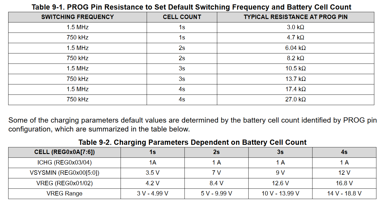
I had to use a 27k resistor on the PROG pin to configure the IC for 4S charging, which would let me adjust charge voltage between 14 and 18.8V over I2C. However, the default charge voltage would be 16.8V, which is bad.
To work around this issue, I removed the temperature sensor resistors on the PCB, to immediately put the charger into a fault state on powerup. This prevents charging, until I manually disable the temperature monitoring through I2C. This means I can change the charge voltage first (and configure everything else too), then disable temperature monitoring to start charging.
bq.setChargeCurrentLimit(4);
bq.setInputCurrentLimit(3.3);
bq.setADC(BQ25798ADC::ADC_15BIT);
bq.disableTS(true);
bq.enableChargingSafetyTimers(false);
bq.enableTermination(false);
bq.setWatchdog(BQ25798Watchdog::WD_2S);
bq.configureThermals(BQ25798ThermalRegulation::TREG_100C, BQ25798ThermalShutdown::TSHUT_120C);
bq.configureMPPT(BQ25798MPPTVOCRatio::VOCPERCENT_0_8125, BQ25798MPPTVOCDelay::VOCDELAY_2S, BQ25798MPPTVOCInterval::VOCINTERVAL_2M);
bq.disableChargerUSBDetection(true);
Most of these are self-explanatory, the only one worth talking about is MPPT. Unfortunately, the BQ25798 doesn't support "proper" MPPT, instead, it measures the open circuit voltage once in a while, and uses a preconfigured percentage of that open circuit voltage as the input target voltage.
Here are the relevant parameters of my solar panel:

The ratio of open-circuit voltage to voltage at Pmax is 18.6V / 22.9V = 0.8122. These are the available options on the BQ25798:

I also set "VOC interval" to 2 minutes, and "VOC delay" to 2 seconds, which is how often charging is interrupted and for how long to wait for the input voltage to stabilize, to measure the open-circuit voltage.
Based on which one of the two available inputs is selected, I need to change some settings as well.
The "secondary" input on all chargers(when the relays are energized) is for charging from the car's generator, for this, I configured 1.25A charge current on each IC, for a total of 5A. I picked this number because it's the most efficient setting based on the curves from the datasheet(shown earlier), and 5A is also roughly the maximum current I am willing to draw over the cigarette lighter socket in my car. I'm thinking about hard-wiring to the generator later, so I can increase charge current to about 10A.
For the "primary" input(when relays are not energized), the first two chargers have their maximum current set to 4A, and MPPT enabled. The third charger's input current limit will have to be set to what the STUSB4500 negotiated with the charger, but I haven't gotten around to writing any STUSB4500 related code yet. The fourth charger is for a second battery, that I will talk about in a later blog.
void setBQMode(int id, bool mode)
{
    bq_modes[id] = mode;
    // Secondary battery primary, generator secondary
    if (id == 0)
    {
        // Seoncdary battery input mode
        if (mode == 0)
        {
            digitalWrite(RELAY0, HIGH);
            selectBQ(0);
            bq.enableMPPT(false);
            bq.setChargeCurrentLimit(1.25);
            bq.setInputCurrentLimit(1.5);
            bq.disableCharging(bq_mode0_disabled[0]);
        }
        // Car generator input mode
        else
        {
            digitalWrite(RELAY0, LOW);
            selectBQ(0);
            bq.enableMPPT(false);
            bq.setChargeCurrentLimit(4);
            bq.setInputCurrentLimit(generator_charge_current / 4);
            bq.disableCharging(bq_mode1_disabled[0]);
        }
    }

    // Solar input primary, generator secondary
    else if (id == 1)
    {
        // Solar input mode
        if (mode == 0)
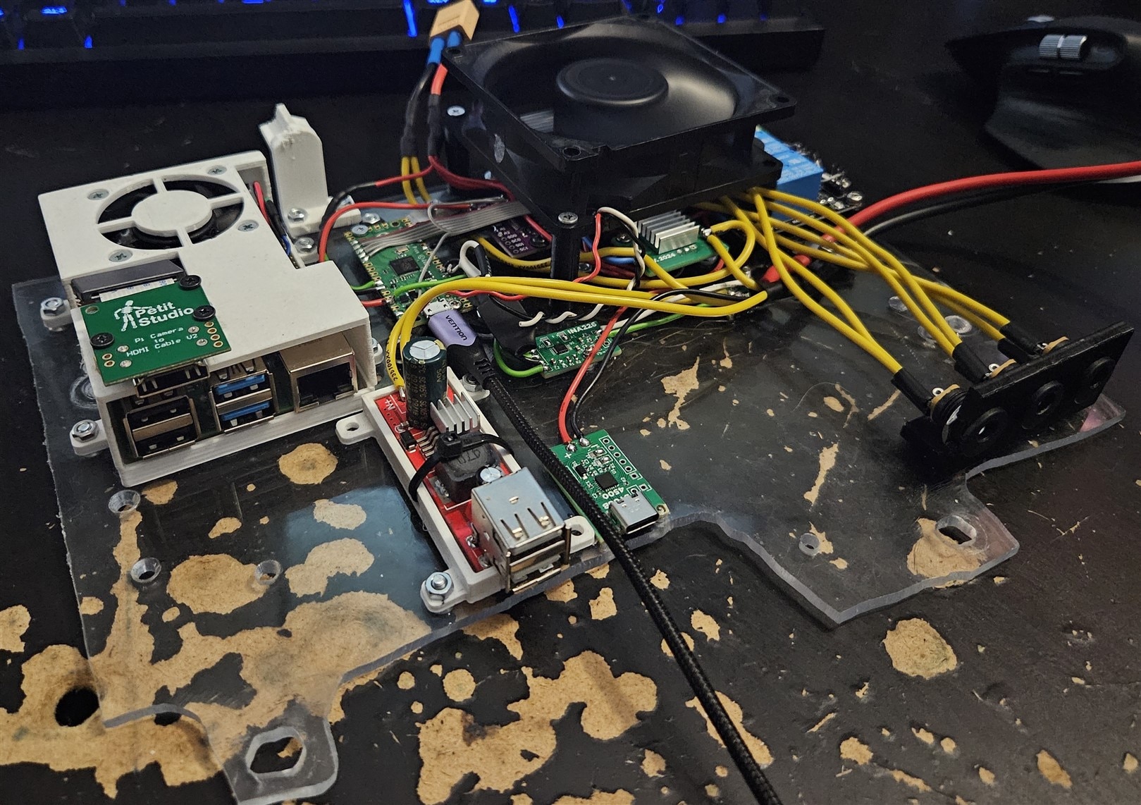
        {
            digitalWrite(RELAY1, HIGH);
            selectBQ(1);
            bq.enableMPPT(true);
            bq.setChargeCurrentLimit(4);
            bq.setInputCurrentLimit(4);
            bq.disableCharging(bq_mode0_disabled[1]);
        }
        // Car generator input mode
        else
        {
            digitalWrite(RELAY1, LOW);
            selectBQ(1);
            bq.enableMPPT(false);
            bq.setChargeCurrentLimit(4);
            bq.setInputCurrentLimit(generator_charge_current / 4);
            bq.disableCharging(bq_mode1_disabled[1]);
        }
    }

    // USB-PD primary, generator secondary
    else if (id == 2)
    {
        // USB-PD mode
        if (mode == 0)
        {
            digitalWrite(RELAY2, HIGH);
            selectBQ(2);
            bq.setChargeCurrentLimit(4);
            bq.setInputCurrentLimit(2.5); // TODO: this should depend on STUSB4500 negotiated power
            bq.disableCharging(bq_mode0_disabled[2]);
        }
        // Car generator input mode
        else
        {
            digitalWrite(RELAY2, LOW);
            selectBQ(2);
            bq.setChargeCurrentLimit(4);
            bq.setInputCurrentLimit(generator_charge_current / 4);
            bq.disableCharging(bq_mode1_disabled[2]);
        }
    }

    // Solar input primary, generator secondary
    else if (id == 3)
    {
        // Solar input mode
        if (mode == 0)
        {
            digitalWrite(RELAY3, HIGH);
            selectBQ(3);
            bq.enableMPPT(true);
            bq.setChargeCurrentLimit(4);
            bq.setInputCurrentLimit(4);
            bq.disableCharging(bq_mode0_disabled[3]);
        }
        // Car generator input mode
        else
        {
            digitalWrite(RELAY3, LOW);
            selectBQ(3);
            bq.enableMPPT(false);
            bq.setChargeCurrentLimit(4);
            bq.setInputCurrentLimit(generator_charge_current / 4);
            bq.disableCharging(bq_mode1_disabled[3]);
        }
    }
}
There is a voltage divider on the car generator input, which is connected to one of the ADC pins on the Pico. The relays are switched based on the voltage sensed on this pin. If the voltage from the generator exceeds 12.6V, it is assumed that the generator is running, and charging can begin. Relays are switched on one-by-one, with a small delay, to not immediately load down the generator. When the voltage drops below 12.6V, the relays are switched back to the secondary input, preventing the possibility of draining the car's own 12V battery.
class Generator
{
    static Averager<float, 10> voltageAverager;
public:
    // ADC voltage multiplier for generator voltage. If one volt is fed to the divider, this is the voltage on the ADC input
    static constexpr float GENERATOR_ADC_V_MULTIPLIER = 0.164;

    static float getRawGeneratorVoltage()
    {
        return (analogRead(ADC) * (3.3 / 1023)) * (1 / GENERATOR_ADC_V_MULTIPLIER);
    }

    static void tick() {
        voltageAverager.add(getRawGeneratorVoltage());
    }

    static float getGeneratorVoltage()
    {
        return voltageAverager.getAverage();
    }
};

Averager<float, 10> Generator::voltageAverager = Averager<float, 10>();
float generatorVoltage = Generator::getGeneratorVoltage();

// Start turning on chargers if generator voltage is above minimum threshold
if(generatorVoltage > GENERATOR_CHG_ON_V && altModeSeq == GENERATOR_OFF) {
  altModeSeq = GENERATOR_ON_BQ0_ON;
}

// Continue turning on chargers if generator voltage is above minimum threshold
if(generatorVoltage > GENERATOR_CHG_OFF_V && altModeSeq >= GENERATOR_ON_BQ0_ON) {
  altModeSeq = (GENERATOR_POWERON_SEQ)((int)altModeSeq + 1);
}

// Set BQ modes based on the current state
if(altModeSeq == GENERATOR_OFF) {
  chargers.setBQMode(0, 0);
  chargers.setBQMode(1, 0);
  chargers.setBQMode(2, 0);
  chargers.setBQMode(3, 0);
}
else if(altModeSeq == GENERATOR_ON_BQ0_ON) {
  chargers.setBQMode(0, 1);
  chargers.setBQMode(1, 0);
  chargers.setBQMode(2, 0);
  chargers.setBQMode(3, 0);
}
else if(altModeSeq == GENERATOR_ON_BQ01_ON) {
  chargers.setBQMode(0, 1);
  chargers.setBQMode(1, 1);
  chargers.setBQMode(2, 0);
  chargers.setBQMode(3, 0);
}
else if(altModeSeq == GENERATOR_ON_BQ012_ON) {
  chargers.setBQMode(0, 1);
  chargers.setBQMode(1, 1);
  chargers.setBQMode(2, 1);
  chargers.setBQMode(3, 0);
}
else if(altModeSeq == GENERATOR_ON_BQ0123_ON) {
  chargers.setBQMode(0, 1);
  chargers.setBQMode(1, 1);
  chargers.setBQMode(2, 1);
  chargers.setBQMode(3, 1);
}
To estimate battery charge left, I made a 4W 4mOhm shunt resistor from two 8mOhm 2512 resistors in parallel, and connected them to an INA226. This lets me monitor both voltage and current, doing coulomb counting in software.
#include <Arduino.h>
#include <Wire.h>
#include "ina.h"

class Battery {
    static constexpr float FULLY_CHARGED_V = 14.375;
    float readings_per_hour;
public:
    INA226 ina;
    float current;
    float voltage;
    float remaining_wh;
    float max_capacity_wh;

    void begin(float battery_max_capacity_wh, TwoWire* i2c, uint8_t ina_address, float ina_shunt_ohms) {
        ina.begin(i2c, ina_address, ina_shunt_ohms, 0.0005);
        ina.setConversionTime(INA226_AVERAGE::AVERAGE_128, INA226_CONVERSION_TIME::_2116US, INA226_CONVERSION_TIME::_2116US);
        float reading_interval_secs = (128 * (2116 + 2116)) / 1000.0 / 1000.0;
        readings_per_hour = 3600.0 / reading_interval_secs;
        this->max_capacity_wh = battery_max_capacity_wh;
        remaining_wh = 0;
    }

    void tick() {
        if(ina.isConversionReady()) {
            current = -ina.readBusCurrent();
            voltage = ina.readBusVoltage();
            float change = (current * voltage) / readings_per_hour;
            remaining_wh += change;
            if(remaining_wh < 0) {
                remaining_wh = 0;
            }
            if(remaining_wh > max_capacity_wh || voltage >= FULLY_CHARGED_V) {
                remaining_wh = max_capacity_wh;
            }
        }
    }
};
All of the ADC readings from BQ25798 modules and the INA226 module, along with measured generator voltage are sent over the serial port as JSON to the host, for logging purposes:
JsonDocument doc;

doc["battery"]["voltage"] = battery.voltage;
doc["battery"]["current"] = battery.current;
doc["battery"]["remainingWh"] = battery.remaining_wh;

JsonArray json_chargers = doc["chargers"].to<JsonArray>();
for (int i = 0; i < 4; i++)
{
chargers.selectBQ(i);
JsonObject json_charger = json_chargers.add<JsonObject>();
json_charger["id"] = i;
json_charger["inputVoltage"] = chargers.bq.getInputVoltage();
json_charger["inputCurrent"] = chargers.bq.getInputCurrent();
json_charger["batteryVoltage"] = chargers.bq.getBatteryVoltage();
json_charger["chargeCurrent"] = chargers.bq.getChargeCurrent();
json_charger["temperature"] = chargers.bq.getDieTemperature();
}

// Add the generator and fan data
doc["generatorVoltage"] = Generator::getRawGeneratorVoltage();
doc["fanSpeed"] = FanControl::fanSpeed;
doc["forceBackupCharging"] = force_backup_charging;

serializeJson(doc, Serial);
Serial.print('\n');
BQ25798 Library
I need to clean up things a little, and add some miscellaneous functionality, but this works well for now.
#pragma once
#include <Wire.h>
enum BQ25798Watchdog
{
WD_DISABLED = 0b000,
WD_500MS = 0b001,
WD_1S = 0b010,
WD_2S = 0b011,
WD_20S = 0b100,
WD_40S = 0b101,
WD_80S = 0b110,
WD_160S = 0b111
};
enum BQ25798ADC
{
ADC_15BIT = 0b00,
ADC_14BIT = 0b01,
ADC_13BIT = 0b10,
ADC_12BIT = 0b11,
ADC_DISABLED = 0b100,
};
enum BQ25798MPPTVOCRatio
{
VOCPERCENT_0_5625 = 0,
VOCPERCENT_0_625 = 1,
VOCPERCENT_0_6875 = 2,
VOCPERCENT_0_75 = 3,
VOCPERCENT_0_8125 = 4,
VOCPERCENT_0_875 = 5,
VOCPERCENT_0_9375 = 6,
VOCPERCENT_1_0 = 7,
};
enum BQ25798MPPTVOCDelay
{
VOCDELAY_50MS = 0,
VOCDELAY_300MS = 1,
VOCDELAY_2S = 2,
VOCDELAY_5S = 3
};
enum BQ25798MPPTVOCInterval
{
VOCINTERVAL_30S = 0,
VOCINTERVAL_2M = 1,
VOCINTERVAL_10M = 2,
VOCINTERVAL_30M = 3
};
enum BQ25798ThermalRegulation
{
TREG_60C = 0,
TREG_80C = 1,
TREG_100C = 2,
TREG_120C = 3
};
enum BQ25798ThermalShutdown
{
TSHUT_150C = 0,
TSHUT_130C = 1,
TSHUT_120C = 2,
TSHUT_85C = 3
};
union BQ25798Status0 {
struct
{
bool VBUS_PRESENT_STAT : 1;
bool AC1_PRESENT_STAT : 1;
bool AC2_PRESENT_STAT : 1;
bool PG_STAT : 1;
bool __rsvd0 : 1;
bool WD_STAT : 1;
bool VINDPM_STAT : 1;
bool IINDPM_STAT : 1;
};
uint8_t raw;
};
union BQ25798Status1 {
struct
{
bool BC1_2_DONE_STAT : 1;
uint8_t VBUS_STAT : 4;
uint8_t CHG_STAT: 3;
};
uint8_t raw;
};
union BQ25798Status2 {
struct
{
bool VBAT_PRESENT_STAT : 1;
bool DPDM_STAT : 1;
bool TREG_STAT : 1;
uint8_t __rsvd0: 3;
uint8_t ICO_STAT: 2;
};
uint8_t raw;
};
union BQ25798Status3 {
struct
{
bool __rsvd0 : 1;
bool PRECHG_TMR_STAT : 1;
bool TRICHG_TMR_STAT : 1;
bool CHG_TMR_STAT : 1;
bool VSYS_STAT : 1;
bool ADC_DONE_STAT : 1;
bool ACRB1_STAT : 1;
bool ACRB2_STAT : 1;
};
uint8_t raw;
};
union BQ25798Status4 {
struct
{
bool TS_HOT_STAT : 1;
bool TS_WARM_STAT : 1;
bool TS_COOL_STAT : 1;
bool TS_COLD_STAT : 1;
bool VBATOTG_LOW_STAT : 1;
bool __rsvd0 : 3;
};
uint8_t raw;
};
union BQ25798Fault0 {
struct
{
bool VAC1_OVP_STAT : 1;
bool VAC2_OVP_STAT : 1;
bool CONV_OCP_STAT : 1;
bool IBAT_OCP_STAT : 1;
bool IBUS_OCP_STAT : 1;
bool VBAT_OVP_STAT : 1;
bool VBUS_OVP_STAT : 1;
bool IBAT_REG_STAT : 1;
};
uint8_t raw;
};
union BQ25798Fault1 {
struct
{
uint8_t __rsvd0 : 2;
bool TSHUT_STAT : 1;
bool __rsvd1 : 1;
bool OTG_UVP_STAT : 1;
bool OTG_OVP_STAT : 1;
bool VSYS_OVP_STAT : 1;
bool VSYS_SHORT_STAT : 1;
};
uint8_t raw;
};
class BQ25798
{
TwoWire *i2c;
public:
void begin(TwoWire* i2c)
{
this->i2c = i2c;
}
void reset()
{
i2c->beginTransmission(0x6B);
i2c->write(0x09);
i2c->endTransmission();
i2c->requestFrom(0x6B, 1);
uint8_t reset = i2c->read();
reset |= 0b01000000;
i2c->beginTransmission(0x6B);
i2c->write(0x09);
i2c->write(reset);
i2c->endTransmission();
}
void setWatchdog(BQ25798Watchdog wdSettings)
{
i2c->beginTransmission(0x6B);
i2c->write(0x10);
i2c->endTransmission();
i2c->requestFrom(0x6B, 1);
uint8_t wdt = i2c->read();
wdt &= 0b11111000;
wdt |= wdSettings;
i2c->beginTransmission(0x6B);
i2c->write(0x10);
i2c->write(wdt);
i2c->endTransmission();
}
void resetWatchdog()
{
i2c->beginTransmission(0x6B);
i2c->write(0x10);
i2c->endTransmission();
i2c->requestFrom(0x6B, 1);
uint8_t wdt = i2c->read();
wdt |= 0b00001000;
i2c->beginTransmission(0x6B);
i2c->write(0x10);
i2c->write(wdt);
i2c->endTransmission();
}
void setADC(BQ25798ADC adcSettings)
{
i2c->beginTransmission(0x6B);
i2c->write(0x2e);
i2c->endTransmission();
i2c->requestFrom(0x6B, 1);
uint8_t adc = i2c->read();
adc &= 0b01001111;
if (adcSettings != ADC_DISABLED)
{
adc |= adcSettings << 4;
adc |= 0b10000000;
}
i2c->beginTransmission(0x6B);
i2c->write(0x2e);
i2c->write(adc);
i2c->endTransmission();
}
float getChargeVoltage() {
i2c->beginTransmission(0x6B);
i2c->write(0x01);
i2c->endTransmission();
i2c->requestFrom(0x6B, 2);
uint16_t reg = ((uint16_t)i2c->read() << 8) | i2c->read();
return reg / 100.0;
}
void setChargeVoltage(float voltage) {
uint16_t reg = voltage * 100;
i2c->beginTransmission(0x6B);
i2c->write(0x01);
i2c->write((uint8_t)(reg >> 8));
i2c->write((uint8_t)(reg & 0xff));
i2c->endTransmission();
}
float getInputVoltage()
{
i2c->beginTransmission(0x6B);
i2c->write(0x35);
i2c->endTransmission();
i2c->requestFrom(0x6B, 2);
uint16_t vbus_mv = ((uint16_t)i2c->read() << 8) | i2c->read();
return vbus_mv / 1000.0;
}
float getBatteryVoltage()
{
i2c->beginTransmission(0x6B);
i2c->write(0x3b);
i2c->endTransmission();
i2c->requestFrom(0x6B, 2);
uint16_t vbat_mv = ((uint16_t)i2c->read() << 8) | i2c->read();
return vbat_mv / 1000.0;
}
float getChargeCurrent()
{
i2c->beginTransmission(0x6B);
i2c->write(0x33);
i2c->endTransmission();
i2c->requestFrom(0x6B, 2);
uint16_t chgcurrent = ((uint16_t)i2c->read() << 8) | i2c->read();
int16_t chgcurrent_signed = static_cast<int16_t>(chgcurrent);
return chgcurrent_signed / 1000.0;
}
float getInputCurrent() {
i2c->beginTransmission(0x6B);
i2c->write(0x31);
i2c->endTransmission();
i2c->requestFrom(0x6B, 2);
uint16_t chgcurrent = ((uint16_t)i2c->read() << 8) | i2c->read();
int16_t chgcurrent_signed = static_cast<int16_t>(chgcurrent);
return chgcurrent_signed / 1000.0;
}
float getDieTemperature()
{
i2c->beginTransmission(0x6B);
i2c->write(0x41);
i2c->endTransmission();
i2c->requestFrom(0x6B, 2);
uint16_t tdie = ((uint16_t)i2c->read() << 8) | i2c->read();
int16_t tdie_signed = static_cast<int16_t>(tdie);
return tdie_signed * 0.5;
}
void disableTS(bool disable)
{
i2c->beginTransmission(0x6B);
i2c->write(0x18);
i2c->endTransmission();
i2c->requestFrom(0x6B, 1);
uint8_t tsctrl = i2c->read();
if (disable)
tsctrl |= 1;
else
tsctrl &= 0b11111110;
i2c->beginTransmission(0x6B);
i2c->write(0x18);
i2c->write(tsctrl);
i2c->endTransmission();
}
void setChargeCurrentLimit(float current) {
uint16_t chgcurrent = current * 100; //10mA resolution
if(chgcurrent > 500) { //5A absolute max
chgcurrent = 500;
}
if(chgcurrent < 5) { // 50mA minimum
chgcurrent = 5;
}
i2c->beginTransmission(0x6B);
i2c->write(0x03);
i2c->endTransmission();
i2c->requestFrom(0x6B, 2);
uint16_t chgreg = ((uint16_t)i2c->read() << 8) | i2c->read();
chgreg &= 0b1111111000000000;
chgreg |= chgcurrent;
i2c->beginTransmission(0x6B);
i2c->write(0x03);
i2c->write((uint8_t)(chgreg >> 8));
i2c->write((uint8_t)(chgreg & 0xff));
i2c->endTransmission();
}
float getChargeCurrentLimit() {
i2c->beginTransmission(0x6B);
i2c->write(0x03);
i2c->endTransmission();
i2c->requestFrom(0x6B, 2);
uint16_t chgcurrent = ((uint16_t)i2c->read() << 8) | i2c->read();
return chgcurrent / 100.0;
}
void setInputCurrentLimit(float current) {
int chgcurrent = current * 100;
if(chgcurrent > 330) { //3.3A absolute max
chgcurrent = 330;
}
if (chgcurrent < 10) // 100mA minimum
{
chgcurrent = 10;
}
i2c->beginTransmission(0x6B);
i2c->write(0x06);
i2c->endTransmission();
i2c->requestFrom(0x6B, 2);
uint16_t chgreg = ((uint16_t)i2c->read() << 8) | i2c->read();
chgreg &= 0b1111111000000000;
chgreg |= chgcurrent;
i2c->beginTransmission(0x6B);
i2c->write(0x06);
i2c->write((uint8_t)(chgreg >> 8));
i2c->write((uint8_t)(chgreg & 0xff));
i2c->endTransmission();
}
float getInputCurrentLimit() {
i2c->beginTransmission(0x6B);
i2c->write(0x06);
i2c->endTransmission();
i2c->requestFrom(0x6B, 2);
uint16_t chgcurrent = ((uint16_t)i2c->read() << 8) | i2c->read();
return chgcurrent / 100.0;
}
void enableChargingSafetyTimers(bool enable) {
i2c->beginTransmission(0x6B);
i2c->write(0x0E);
i2c->endTransmission();
i2c->requestFrom(0x6B, 1);
uint8_t chgctrl = i2c->read();
if(enable) {
chgctrl |= 0b00111000;
}
else {
chgctrl &= 0b11000111;
}
i2c->beginTransmission(0x6B);
i2c->write(0x0E);
i2c->write(chgctrl);
i2c->endTransmission();
}
void enableTermination(bool enable) {
i2c->beginTransmission(0x6B);
i2c->write(0x0F);
i2c->endTransmission();
i2c->requestFrom(0x6B, 1);
uint8_t chgctrl = i2c->read();
if(enable) {
chgctrl |= 0b00000010;
}
else {
chgctrl &= 0b11111101;
}
i2c->beginTransmission(0x6B);
i2c->write(0x0F);
i2c->write(chgctrl);
i2c->endTransmission();
}
void setPrechargeCurrent(float current) {
uint8_t current_reg = current / 0.04;
if(current_reg > 50) {
current_reg = 50;
}
i2c->beginTransmission(0x6B);
i2c->write(0x08);
i2c->endTransmission();
i2c->requestFrom(0x6B, 1);
uint8_t chgctrl = i2c->read();
chgctrl &= 0b11000000;
chgctrl |= current_reg;
i2c->beginTransmission(0x6B);
i2c->write(0x08);
i2c->write(chgctrl);
i2c->endTransmission();
}
void forceMeasureVINDPM() {
i2c->beginTransmission(0x6B);
i2c->write(0x13);
i2c->endTransmission();
i2c->requestFrom(0x6B, 1);
uint8_t chgctrl = i2c->read();
chgctrl |= 0b00000001;
i2c->beginTransmission(0x6B);
i2c->write(0x13);
i2c->write(chgctrl);
i2c->endTransmission();
}
void setVINDPMVoltage(float voltage) {
uint8_t voltage_reg = voltage * 10;
if(voltage_reg > 220) {
voltage_reg = 220;
}
if(voltage_reg < 36) {
voltage_reg = 36;
}
i2c->beginTransmission(0x6B);
i2c->write(0x5);
i2c->write(voltage_reg);
i2c->endTransmission();
}
void enableMPPT(bool enable) {
i2c->beginTransmission(0x6B);
i2c->write(0x15);
i2c->endTransmission();
i2c->requestFrom(0x6B, 1);
uint8_t mppt = i2c->read();
if(enable) {
mppt |= 0b00000001;
}
else {
mppt &= 0b11111110;
}
i2c->beginTransmission(0x6B);
i2c->write(0x15);
i2c->write(mppt);
i2c->endTransmission();
}
void disableChargerUSBDetection(bool disable) {
i2c->beginTransmission(0x6B);
i2c->write(0x11);
i2c->endTransmission();
i2c->requestFrom(0x6B, 1);
uint8_t chgctrl = i2c->read();
if(disable) {
chgctrl &= 0b10111111;
}
else {
chgctrl |= 0b01000000;
}
i2c->beginTransmission(0x6B);
i2c->write(0x11);
i2c->write(chgctrl);
i2c->endTransmission();
}
void configureThermals(BQ25798ThermalRegulation regulation, BQ25798ThermalShutdown shutdown) {
uint8_t _regulation = regulation << 6;
uint8_t _shutdown = shutdown << 4;
i2c->beginTransmission(0x6B);
i2c->write(0x16);
i2c->endTransmission();
i2c->requestFrom(0x6B, 1);
uint8_t thermal = i2c->read();
thermal &= 0b00001111;
thermal |= (_regulation | _shutdown);
i2c->beginTransmission(0x6B);
i2c->write(0x16);
i2c->write(thermal);
i2c->endTransmission();
}
void configureMPPT(BQ25798MPPTVOCRatio ratio, BQ25798MPPTVOCDelay delay, BQ25798MPPTVOCInterval interval) {
uint8_t _interval = interval << 1;
uint8_t _delay = delay << 3;
uint8_t _ratio = ratio << 5;
i2c->beginTransmission(0x6B);
i2c->write(0x15);
i2c->endTransmission();
i2c->requestFrom(0x6B, 1);
uint8_t mppt = i2c->read();
mppt &= 0b00000001;
mppt |= (_interval | _delay | _ratio);
i2c->beginTransmission(0x6B);
i2c->write(0x15);
i2c->write(mppt);
}
void disableCharging(bool disable) {
i2c->beginTransmission(0x6B);
i2c->write(0x0F);
i2c->endTransmission();
i2c->requestFrom(0x6B, 1);
uint8_t chgctrl = i2c->read();
if(disable) {
chgctrl &= 0b11011111;
}
else {
chgctrl |= 0b00100000;
}
i2c->beginTransmission(0x6B);
i2c->write(0x0F);
i2c->write(chgctrl);
i2c->endTransmission();
}
BQ25798Status0 getStatus0()
{
i2c->beginTransmission(0x6B);
i2c->write(0x1b);
i2c->endTransmission();
i2c->requestFrom(0x6B, 1);
uint8_t status0 = i2c->read();
BQ25798Status0 status;
status.raw = status0;
return status;
}
BQ25798Status1 getStatus1()
{
i2c->beginTransmission(0x6B);
i2c->write(0x1c);
i2c->endTransmission();
i2c->requestFrom(0x6B, 1);
uint8_t status1 = i2c->read();
BQ25798Status1 status;
status.raw = status1;
return status;
}
BQ25798Status2 getStatus2()
{
i2c->beginTransmission(0x6B);
i2c->write(0x1d);
i2c->endTransmission();
i2c->requestFrom(0x6B, 1);
uint8_t status2 = i2c->read();
BQ25798Status2 status;
status.raw = status2;
return status;
}
BQ25798Status3 getStatus3()
{
i2c->beginTransmission(0x6B);
i2c->write(0x1e);
i2c->endTransmission();
i2c->requestFrom(0x6B, 1);
uint8_t status3 = i2c->read();
BQ25798Status3 status;
status.raw = status3;
return status;
}
BQ25798Status4 getStatus4()
{
i2c->beginTransmission(0x6B);
i2c->write(0x1f);
i2c->endTransmission();
i2c->requestFrom(0x6B, 1);
uint8_t status4 = i2c->read();
BQ25798Status4 status;
status.raw = status4;
return status;
}
BQ25798Fault0 getFault0()
{
i2c->beginTransmission(0x6B);
i2c->write(0x20);
i2c->endTransmission();
i2c->requestFrom(0x6B, 1);
uint8_t fault0 = i2c->read();
BQ25798Fault0 fault;
fault.raw = fault0;
return fault;
}
BQ25798Fault1 getFault1()
{
i2c->beginTransmission(0x6B);
i2c->write(0x21);
i2c->endTransmission();
i2c->requestFrom(0x6B, 1);
uint8_t fault1 = i2c->read();
BQ25798Fault1 fault;
fault.raw = fault1;
return fault;
}
void printStatus0(BQ25798Status0 status0, char* pre = nullptr) {
Serial.print(pre);
Serial.print("IINDPM_STAT: ");
Serial.println(status0.IINDPM_STAT ? "In IINDPM regulation or IOTG regulation" : "Normal");
Serial.print(pre);
Serial.print("VINDPM_STAT: ");
Serial.println(status0.VINDPM_STAT ? "In VINDPM regulation or VOTG regulation" : "Normal");
Serial.print(pre);
Serial.print("WD_STAT: ");
Serial.println(status0.WD_STAT ? "WD timer expired" : "Normal");
Serial.print(pre);
Serial.print("PG_STAT: ");
Serial.println(status0.PG_STAT ? "Power good" : "NOT in power good status");
Serial.print(pre);
Serial.print("AC2_PRESENT_STAT: ");
Serial.println(status0.AC2_PRESENT_STAT ? "VAC2 present" : "VAC2 NOT present");
Serial.print(pre);
Serial.print("AC1_PRESENT_STAT: ");
Serial.println(status0.AC1_PRESENT_STAT ? "VAC1 present" : "VAC1 NOT present");
Serial.print(pre);
Serial.print("VBUS_PRESENT_STAT: ");
Serial.println(status0.VBUS_PRESENT_STAT ? "VBUS present" : "VBUS NOT present");
}
void printStatus1(BQ25798Status1 status1, char* pre = nullptr) {
Serial.print(pre);
Serial.print("CHG_STAT: ");
switch(status1.CHG_STAT) {
case 0:
Serial.println("Not Charging");
break;
case 1:
Serial.println("Trickle Charge");
break;
case 2:
Serial.println("Pre-charge");
break;
case 3:
Serial.println("Fast charge (CC mode)");
break;
case 4:
Serial.println("Taper Charge (CV mode)");
break;
case 6:
Serial.println("Top-off Timer Active Charging");
break;
case 7:
Serial.println("Charge Termination Done");
break;
default:
Serial.println("Reserved");
break;
}
Serial.print(pre);
Serial.print("VBUS_STAT: ");
switch(status1.VBUS_STAT) {
case 0:
Serial.println("No Input or BHOT or BCOLD in OTG mode");
break;
case 1:
Serial.println("USB SDP (500mA)");
break;
case 2:
Serial.println("USB CDP (1.5A)");
break;
case 3:
Serial.println("USB DCP (3.25A)");
break;
case 4:
Serial.println("Adjustable High Voltage DCP (HVDCP) (1.5A)");
break;
case 5:
Serial.println("Unknown adaptor (3A)");
break;
case 6:
Serial.println("Non-Standard Adapter (1A/2A/2.1A/2.4A)");
break;
case 7:
Serial.println("In OTG mode");
break;
case 8:
Serial.println("Not qualified adaptor");
break;
case 11:
Serial.println("Device directly powered from VBUS");
break;
case 12:
Serial.println("Backup Mode");
break;
default:
Serial.println("Reserved");
break;
}
Serial.print(pre);
Serial.print("BC1_2_DONE_STAT: ");
Serial.println(status1.BC1_2_DONE_STAT ? "BC1.2 or non-standard detection complete" : "BC1.2 or non-standard detection NOT complete");
}
void printStatus2(BQ25798Status2 status2, char* pre = nullptr) {
Serial.print(pre);
Serial.print("ICO_STAT: ");
switch(status2.ICO_STAT) {
case 0:
Serial.println("ICO disabled");
break;
case 1:
Serial.println("ICO optimization in progress");
break;
case 2:
Serial.println("Maximum input current detected");
break;
default:
Serial.println("Reserved");
break;
}
Serial.print(pre);
Serial.print("TREG_STAT: ");
Serial.println(status2.TREG_STAT ? "Device in thermal regulation" : "Normal");
Serial.print(pre);
Serial.print("DPDM_STAT: ");
Serial.println(status2.DPDM_STAT ? "The D+/D- detection is ongoing" : "The D+/D- detection is NOT started yet, or the detection is done");
Serial.print(pre);
Serial.print("VBAT_PRESENT_STAT: ");
Serial.println(status2.VBAT_PRESENT_STAT ? "VBAT present" : "VBAT NOT present");
}
void printStatus3(BQ25798Status3 status3, char* pre = nullptr) {
Serial.print(pre);
Serial.print("ACRB2_STAT: ");
Serial.println(status3.ACRB2_STAT ? "ACFET2-RBFET2 is placed" : "ACFET2-RBFET2 is NOT placed");
Serial.print(pre);
Serial.print("ACRB1_STAT: ");
Serial.println(status3.ACRB1_STAT ? "ACFET1-RBFET1 is placed" : "ACFET1-RBFET1 is NOT placed");
Serial.print(pre);
Serial.print("ADC_DONE_STAT: ");
Serial.println(status3.ADC_DONE_STAT ? "Conversion complete" : "Conversion NOT complete");
Serial.print(pre);
Serial.print("VSYS_STAT: ");
Serial.println(status3.VSYS_STAT ? "In VSYSMIN regulation (VBAT < VSYSMIN)" : "Not in VSYSMIN regulation (VBAT > VSYSMIN)");
Serial.print(pre);
Serial.print("CHG_TMR_STAT: ");
Serial.println(status3.CHG_TMR_STAT ? "Safety timer expired" : "Normal");
Serial.print(pre);
Serial.print("TRICHG_TMR_STAT: ");
Serial.println(status3.TRICHG_TMR_STAT ? "Safety timer expired" : "Normal");
Serial.print(pre);
Serial.print("PRECHG_TMR_STAT: ");
Serial.println(status3.PRECHG_TMR_STAT ? "Safety timer expired" : "Normal");
}
void printStatus4(BQ25798Status4 status4, char* pre = nullptr) {
Serial.print(pre);
Serial.print("VBATOTG_LOW_STAT: ");
Serial.println(status4.VBATOTG_LOW_STAT ? "The battery volage is too low to enable the OTG operation" : "The battery volage is high enough to enable the OTG operation");
Serial.print(pre);
Serial.print("TS_COLD_STAT: ");
Serial.println(status4.TS_COLD_STAT ? "TS status is in cold range" : "TS status is NOT in cold range");
Serial.print(pre);
Serial.print("TS_COOL_STAT: ");
Serial.println(status4.TS_COOL_STAT ? "TS status is in cool range" : "TS status is NOT in cool range");
Serial.print(pre);
Serial.print("TS_WARM_STAT: ");
Serial.println(status4.TS_WARM_STAT ? "TS status is in warm range" : "TS status is NOT in warm range");
Serial.print(pre);
Serial.print("TS_HOT_STAT: ");
Serial.println(status4.TS_HOT_STAT ? "TS status is in hot range" : "TS status is NOT in hot range");
}
void printFault0(BQ25798Fault0 fault0, char* pre = nullptr) {
Serial.print(pre);
Serial.print("IBAT_REG_STAT: ");
Serial.println(fault0.IBAT_REG_STAT ? "Device in battery discharging current regulation" : "Normal");
Serial.print(pre);
Serial.print("VBUS_OVP_STAT: ");
Serial.println(fault0.VBUS_OVP_STAT ? "Device in over voltage protection" : "Normal");
Serial.print(pre);
Serial.print("VBAT_OVP_STAT: ");
Serial.println(fault0.VBAT_OVP_STAT ? "Device in over voltage protection" : "Normal");
Serial.print(pre);
Serial.print("IBUS_OCP_STAT: ");
Serial.println(fault0.IBUS_OCP_STAT ? "Device in over current protection" : "Normal");
Serial.print(pre);
Serial.print("IBAT_OCP_STAT: ");
Serial.println(fault0.IBAT_OCP_STAT ? "Device in over current protection" : "Normal");
Serial.print(pre);
Serial.print("CONV_OCP_STAT: ");
Serial.println(fault0.CONV_OCP_STAT ? "Device in over current protection" : "Normal");
Serial.print(pre);
Serial.print("VAC2_OVP_STAT: ");
Serial.println(fault0.VAC2_OVP_STAT ? "Device in over voltage protection" : "Normal");
Serial.print(pre);
Serial.print("VAC1_OVP_STAT: ");
Serial.println(fault0.VAC1_OVP_STAT ? "Device in over voltage protection" : "Normal");
}
void printFault1(BQ25798Fault1 fault1, char* pre = nullptr) {
Serial.print(pre);
Serial.print("VSYS_SHORT_STAT: ");
Serial.println(fault1.VSYS_SHORT_STAT ? "Device in SYS short circuit protection" : "Normal");
Serial.print(pre);
Serial.print("VSYS_OVP_STAT: ");
Serial.println(fault1.VSYS_OVP_STAT ? "Device in SYS over voltage protection" : "Normal");
Serial.print(pre);
Serial.print("OTG_OVP_STAT: ");
Serial.println(fault1.OTG_OVP_STAT ? "Device in OTG over voltage" : "Normal");
Serial.print(pre);
Serial.print("OTG_UVP_STAT: ");
Serial.println(fault1.OTG_UVP_STAT ? "Device in OTG under voltage" : "Normal");
Serial.print(pre);
Serial.print("TSHUT_STAT: ");
Serial.println(fault1.TSHUT_STAT ? "Device in thermal shutdown protection" : "Normal");
}
void printAllStatus(char* pre = nullptr) {
BQ25798Status0 status0 = getStatus0();
BQ25798Status1 status1 = getStatus1();
BQ25798Status2 status2 = getStatus2();
BQ25798Status3 status3 = getStatus3();
BQ25798Status4 status4 = getStatus4();
BQ25798Fault0 fault0 = getFault0();
BQ25798Fault1 fault1 = getFault1();
Serial.print(pre);
Serial.println("==== STATUS ====");
printStatus0(status0, pre);
printStatus1(status1, pre);
printStatus2(status2, pre);
printStatus3(status3, pre);
printStatus4(status4, pre);
Serial.print(pre);
Serial.println("==== FAULT ====");
printFault0(fault0, pre);
printFault1(fault1, pre);
}
};
Assembly
A good place to mount all the electronics is the top of the glovebox, so I cut a piece of plexiglas to fit inside, and mounted all the electronics discussed so far to it.
I opted for adding a Raspberry Pi 4 as well, because the Cortex-A9 processors in the Zynq won't have enough performance to do everything I need, even with help from the FPGA.
To power the Pi 4, I mounted a 5V buck regulator as well, which also has two USB outputs in case I want to charge something from the lead acid pack.
The HDMI connector on top of the Pi 4 is an adapter that lets me use an HDMI cable to connect MIPI CSI/DSI devices, I'll use this to connect the Pi HQ camera that will be in the front of the car, while the webcam supplied will be in the back. The Arty Z7 will be connected to the Pi 4 through Ethernet.
The XT60 connector in the back, behind the fan, is the power input from the cigarette lighter socket, connected to input 1 on all the chargers. The cable on the right goes to the battery pack.
I also added 3 barrel jack connectors for the two solar panel inputs, and second battery input, along with an 80mm fan to cool the chargers. The fan is controlled through the Pico, and it is set up to automatically adjust its speed based on temperature.

