The core of the ADAS system will be an Object Recognition model, detecting traffic signs, lights, and speed limits. The two main features the blogs will be focusing on are traffic light change notifications and speeding warnings.
The Dataset
For training such an object recognition model, a vast dataset is required. I could not find anything ready-made that fits my usage, so the only option left is to make my own.
The first step is capturing a lot of driving footage. With the video streaming system implemented in my previous blog, this was made very simple. All I had to do was use my car as regular, and video files automatically started gathering on my server.
The next step is to extract frames(images) from the video. I could just extract every single frame, but that would result in millions of images, most of them not even containing objects I care about. My preferred method of doing this is playing the videos in VLC Media Player, and using its “Take video snapshot” feature. I rebound the keyboard shortcut for this to the “S” key, and all that’s left is to play the video at 3x speed and mash “S” whenever something interesting is visible. VLC will save the frames in .png format to my home folder, ready for labeling.
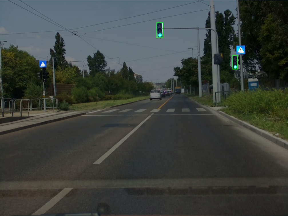
I used Roboflow for manually labeling the images, the free version was enough to do this. Going through every single image, a rectangle needs to be drawn over objects that I want the model to later recognize, and also given the correct label, identifying what sort of object it is.
The Strategy
For acceptable results, I need several thousand images for the training data, each correctly labeled. Doing this takes an insane amount of time and effort, which is not ideal.
To make this process less miserable, I decided to do the following:
- Find a really accurate model, not caring about inference speed or training time, only accuracy/precision. This will be referred to as the “foundation model”
- Label around 1000 images, then train the foundation model on them
- Use the trained foundation model to label another batch of 1000 images
- Go through the AI-labeled images and manually correct its mistakes
- Train the foundation model with 2000 images now
- Repeat
I chose YOLOv9 as the foundation model. It was more accurate than any other model I tested, including DETR and almost every YOLO version.
The model is available in several different sizes:
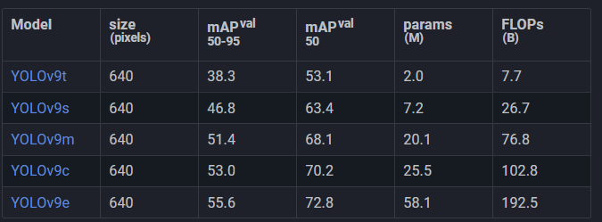
The bigger models take longer to train, require more memory, and do inference slower. This was not an issue though, since as mentioned earlier, this model will be used for dataset creation only, and not for running on the finished device.
To get the absolute best accuracy and precision, I chose the largest model, and trained it at a size of 1440, which corresponds to the resolution of the video output of my capture setup. This configuration requires a very high amount of VRAM though.
Training
Getting the training process to work without running out of memory required me to set the batch size to 4. This isn’t great, but not a huge problem either.
Here’s my attempt at an oversimplified explanation of what batch size does:
During training, a piece of training data(image) is taken and fed through the model. The output is then compared to the labels on the training data (the ground truth). The model’s parameters are then adjusted, so the output matches the expected output more closely. This is what happens with a batch size of 1.
With a batch size of, let’s say 4, instead of adjusting the model’s parameters after each image, the applied adjustment is the averaged adjustments from 4 images.
Having a larger batch size is therefore ideal, because the model will be updated to perform better on a variety of images at once, instead of performing better on one particular image.
Increasing batch size results in a huge increase in required VRAM to train though. The recommended default batch size for YOLO models is usually 16. Going above this most likely doesn’t bring any real benefits, even if there is sufficient memory.
Going under is possible, and might not even result in worse accuracy/precision, but the training process will be more unstable.
A batch size of 4 seems to be the minimum value that still achieves good results in my testing.
There are also some data augmentation settings that I changed. In most object recognition scenarios, it is possible to artificially increase the size of a dataset. For example, every image can be rotated 90, 180, and 270 degrees. This will quadruple the size of the dataset, and also “teach” the model to recognize rotated objects well.
The library I’m using for training (ultralytics) can automatically apply these augmentations during training on-the-fly, without actually having to generate and store these modified images.
The default augmentation settings were chosen to provide the best results for the most common scenarios, but that won’t work great for this project. Keep in mind, values specified here, like “20 degrees” or “10%” doesn’t mean that every image will be, let's say rotated by 10 degrees or 10%, but that a random value between 0 and that limit will be used.
Here are some of the available augmentations:
- Color/brightness adjustments (hsv_h, hsv_s, hsv_v): the defaults work well enough, the goal is to simulate different lighting conditions and camera settings, while keeping enough of the original color so it can be recognized. For example, changing the hue too much might turn a red traffic light into green, which the model would then recognize and green, then be penalized for during training, because it’s red according to the dataset.
- Rotation (degrees): the default setting is off, but I chose to enable it with a range of 15 degrees. Care must be taken not to rotate the images too much, as this could cut off objects, or make them potentially look like something else (for example, an upwards pointing arrow might turn into a sideways pointing one)
- Translate: move the images horizontally/vertically. The default option of 10% in any direction works well.
- Scale: zoom in on images. The default of 50% works well.
- Flip/mirror (flipud, fliplr): By default, fliplr(vertical mirroring) is enabled with a 50% chance. This is very bad for us, as we need to preserve the left-right “direction” of objects, like arrows.
- Mosaic: combines multiple images into a grid. The default is on, which is fine.
- Erasing: randomly deletes some portion of the image. This is on with 40% chance by default, and works well.
To find the best parameters, I wrote a small script that trains the smallest YOLOv9 model at a lower resolution, and compares multiple values for each of these settings. This isn’t perfect, as the large model might not behave the same way as the small one, and same for the resolution, but I do not have months to wait for a hyperparameter tune to finish, so it will have to do.
I ended up with this command to start the training with my selected settings:
yolo detect train data=dataset_1000/data.yaml model=yolov9e.pt epochs=300 patience=20 save_period=10 cache=ram device=1 imgsz=1440 batch=4 plots=True fliplr=0 degrees=15
Epochs is how long to train for, and patience means “if there’s no improvement in accuracy/precision after this many epochs, stop training”
Training time depends on the dataset size. At first, with the first 1000 images, it took about a day.
After repeating the steps described above for training, auto-labeling, manually correcting, and training again, I ended up with a dataset of almost 6000 images. I trained a model on this one last time, taking over a week to finish.
Final Model
The trained YOLOv9e model is way too compute intensive and slow to use in the final project, so a smaller and faster model will be used instead. My picks would either be YOLO-NAS, or the new YOLO11 models, which are very quick but still perform well. Ultimately, the model choice will be dictated by the hardware I end up using for running inference.
However, the real-time video streaming implemented before lets me run inference on the remote server, which is the same machine that was used for the training. This means that resource intensive models could still be used, although the latency of transmitting video makes it not ideal in many scenarios.
For now, I will be sticking to running a smaller model locally, on the Zynq FPGA.
Xilinx DPU
Xilinx has an IP block called the “DPU” available. It is an inference accelerator that connects over AXI to a host CPU running Linux. Many of the resource intensive parts of running inference can then be offloaded to the DPU.
Vivado version 2020.1 is used for compatibility reasons.
In the references section at the end, I have multiple resources that go into detail about this, so I’ll only give a quick overview.
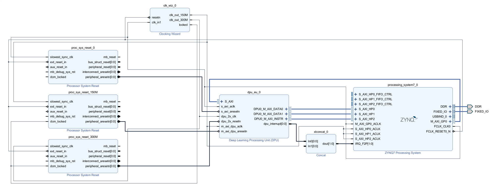
- The first step is to configure the PS(ARM CPU) and PL(FPGA) in Vivado.
- Add the Zynq Processing system, enable 3 AXI HP ports, and the PL to PS interrupts.
- Add the DPU, configure it with the desired settings, and hook it up to the AXI ports. The DPU has multiple configurations that determine inference speed, block RAM usage, and DSP usage. The Zynq-7020 is quite limited, so a relatively “lightweight” configuration has to be used.
- Add a Clocking Wizard to generate 150MHz and 300MHz clocks from the Zynq’s clock.
- Add Processor System Resets for the Zynq, 150MHz, and 300MHz clocks.
The final block diagram looks like this:
Then generate the bitstream, and export hardware.
Petalinux
Petalinux is a linux “distribution” made for Xilinx devices. It’s not really a distribution, it’s more of build system for creating customized OSes. It uses Yocto at its core, but simplifies the build process to a few commands.
As with the Vivado part, there are some resources linked below that describe what to do, so I’ll just very briefly summarize:
For compatibility reasons, an old Petalinux version has to be used, which requires Ubuntu 18.04 to work properly.
To enable DPU support, a few files need to be added to the Petalinux project, and a few settings changed in build configurations.
Building the OS gives us the bootloader files that need to be copied to a FAT32 partition at the start of an SD card, and the root filesystem, which needs to be extracted to an EXT4 partition on the same SD card.
After inserting the SD card into the Arty Z7, the boot process can be observed over UART, and the “root”/”root” credentials can be used to log in. SSH is also enabled by default, but an incorrect password error is shown once on each login, even if the password is correct. Some sort of security measure I guess?
During boot, the following is shown about the DPU:
[DPU][957]Found DPU signature addr = 0x4f000000 in device-tree
[DPU][957]Checking DPU signature at addr = 0x4ff00000,
[DPU][957]DPU signature checking done!
Linux can see the DPU, so that is promising.
Converting Models
For running models on the DPU, they have to be converted to a special format first. This is quite an involved process, that requires first converting to Tensorflow’s “Frozen Graph” format first, then quantized by a Xilinx tool (which takes many hours to complete), and then compiled into an .ELF file.
The guide mentioned before also describes this process in detail, but I won’t go into any details in this blog, as I'm not fully done with it myself, and it would mostly be duplicate information from the resources linked at the bottom. Also, maybe some issue comes up later while I'm waiting for quantization, that I can work on in the meantime. Foreshadowing is a literary device tha...
Trying Prebuilt Models
Both the Xilinx DNNDK and the guide mentioned previously includes prebuilt models along with the code to run them, so while the quantization process was running, I decided to try them.
The Xilinx examples didn’t work at all, reporting a mismatch between my DPU configuration and what they built the examples with.
So I tried the prebuilt examples from the guide. I ran the command, and… the Arty-Z7 reset on its own.
After going through the C++ code supplied with the examples, I removed everything unnecessary and added debug prints. The function that causes the Arty to reset is dpuRunTask().
This is not a good sign, as that function is provided by the Xilinx DPU libraries, and I cannot debug them easily.
However, it seemed weird that a userspace software issue would reset the Zynq without any trace of errors, or a kernel panic, or similar.
Hardware Issues
I noticed the red LED on the Arty turning off for a brief period when the reset happens. This could mean there is a power issue.
I tried powering the Arty with all kinds of power supplies, through USB with 5V, and from the barrel jack, with everything between 7V and 15V.
I probed the big MLCC capacitors around the Zynq-7020, and found this on the 1.0V rail during the reset:
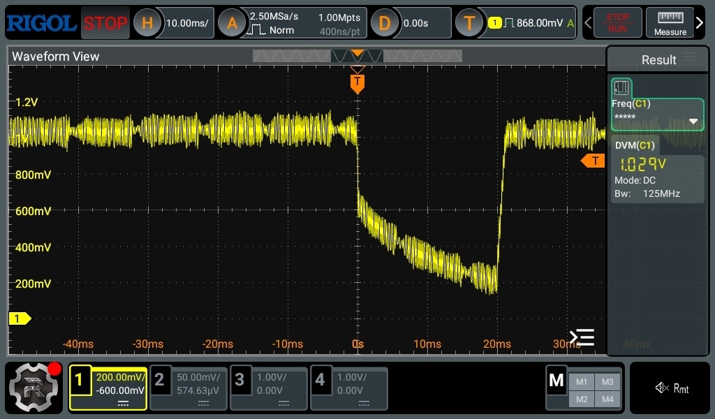
That doesn’t look good, but maybe the DC-DC converter is just powering off after the Zynq resets, as some enable signal is de-asserted, or something.
Let’s dig into the schematics:
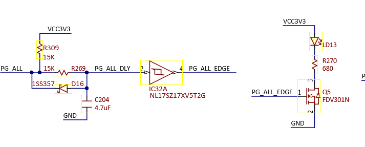
The LED is switched by a low-side FET, which is switched by PG_ALL_EDGE, which is essentially just PG_ALL. That seems to come from the main PMIC:
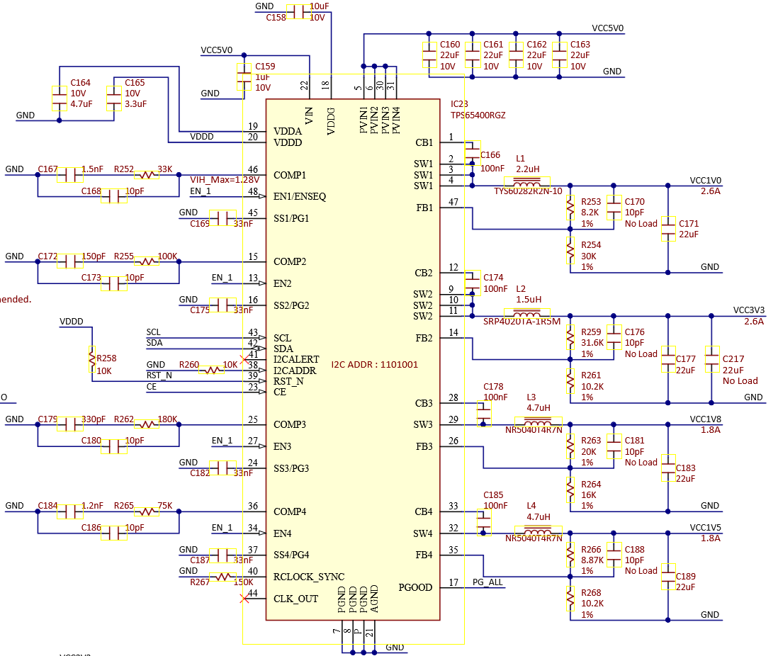
So the PMIC is reporting no power-good during the reset. This still doesn’t mean much, the PMIC could be turned off on purpose.
Looking at the schematic further, the only ways to turn it off are:
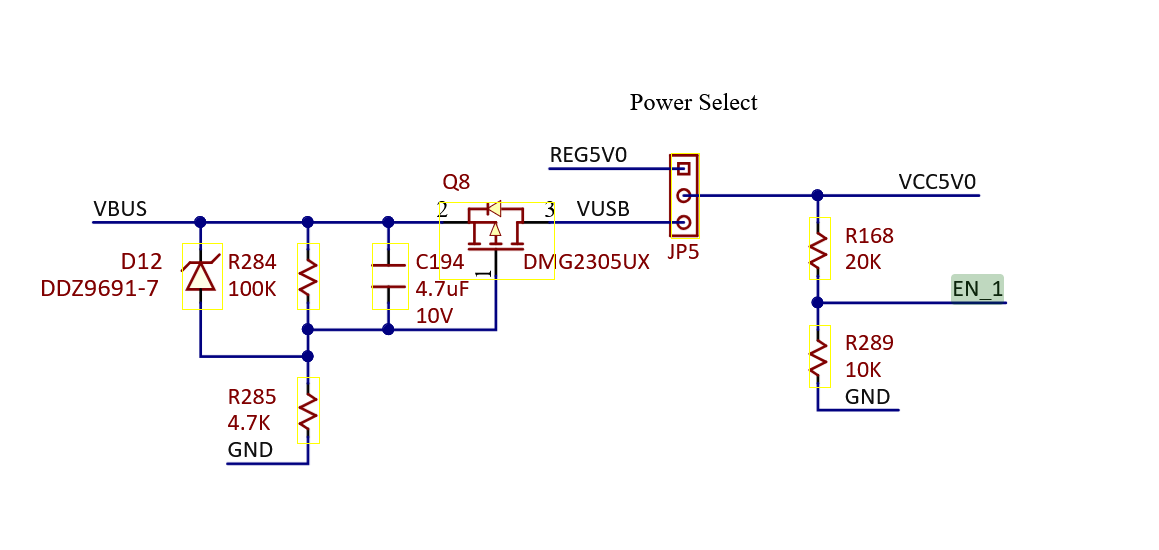
- Using the EN_1 signal, which is tied to all four buck converter enable pins on the PMIC
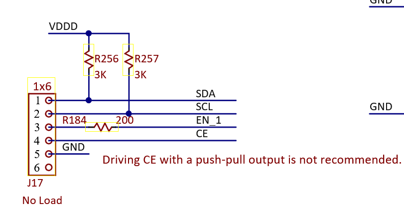
- Using the CE signal, which also disables all four buck converters along with the entire PMIC
- There is also an SMBus interface, but it is not connected to anything, other than a 1x6 header.
EN_1 is controlled only by the power source selection jumper, so that's ruled out.
CE is connected only to the same jumper that SMBus goes to, so that’s not it either.
This means that the PMIC is either turning off the 1V rail for some reason, or it cannot keep up with generating it.
The only idea I had was to add some bulk capacitance to the 1V rail, maybe it’s just a very brief transient that’s triggering some kind of overload protection in the PMIC.
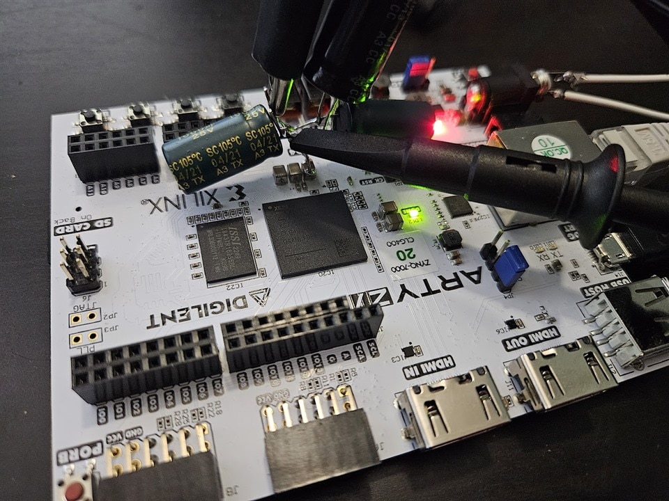
Unfortunately, the reset still happened after running the DPU code. However, the PMIC recovered within 20ms previously, but with the large amount of capacitance added, it took up to 10 seconds for it to bring the rail up to 1V again. I’m not sure this is useful information, but I found it interesting.
(I tried with a 1000uF low ESR cap initially, and then added more caps, up to about 10000uF total. The “recovery time” increased with capacitance)
SMBus Magic
My last hope was to use the SMBus interface to try and get some useful information. I hooked up an Arduino to be able to communicate with the PMIC.
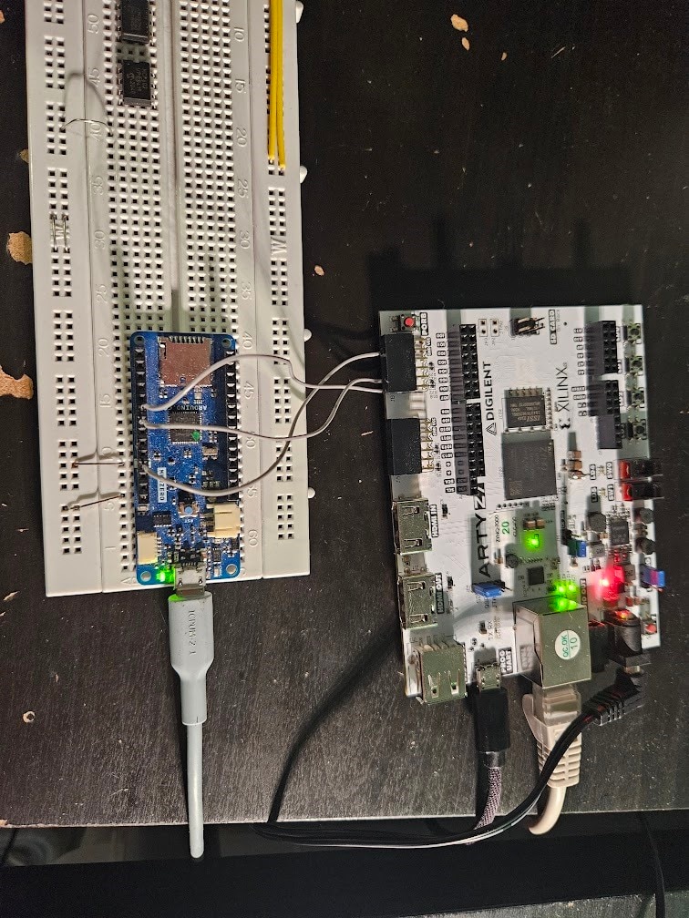
(the SMBus pins are under the second PMOD connector)
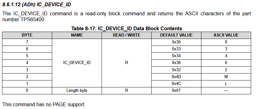
The first step was to try and get the device ID:
void getDevId() {
  Wire.beginTransmission(0x69);
  Wire.write(0xAD);
  Wire.endTransmission(false);
  Wire.requestFrom(0x69, 8);
  Serial.print("Device ID: ");
  for(int i = 0; i < 8; i++) {
    Serial.print(Wire.read(), HEX);
    Serial.print(" ");
  }
  Serial.println();
}

void setup() {
  Serial.begin(115200);
  Wire.begin();
  getDevId();
}

void loop() {}
I got this output:
Device ID: 7 4C 4D 32 36 34 33 30
Which is the expected value:
Then I checked what happens with STATUS_WORD during a reset:
byte getStatus() {
  Wire.beginTransmission(0x69);
  Wire.write(0x79);
  Wire.endTransmission(false);
  Wire.requestFrom(0x69, 2);
  byte upper = Wire.read();
  byte lower = Wire.read();

  return lower;
}

byte lastStatus = 0;
void loop() {
  //getDevId();
  byte status = getStatus();
  if(status != lastStatus) {
    Serial.print("Status: ");
    Serial.println(status, BIN);
    lastStatus = status;
  }

  delay(10);
}
During normal operation, the register was 0. When the reset happened, it became 11000 for a moment.
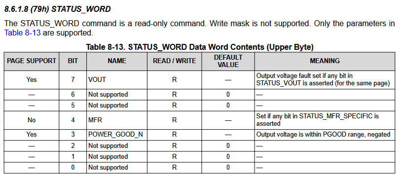
That means power good is no longer true, and something was set in STATUS_MFR_SPECIFIC.
Reading that register, we get 0 when normally operating, and 1 during a reset.
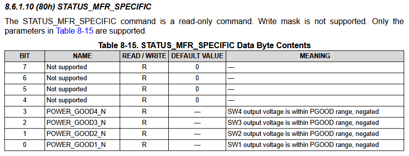
This confirmed that the issue is the 1V rail, which is SW1, but still no idea what’s actually happening.
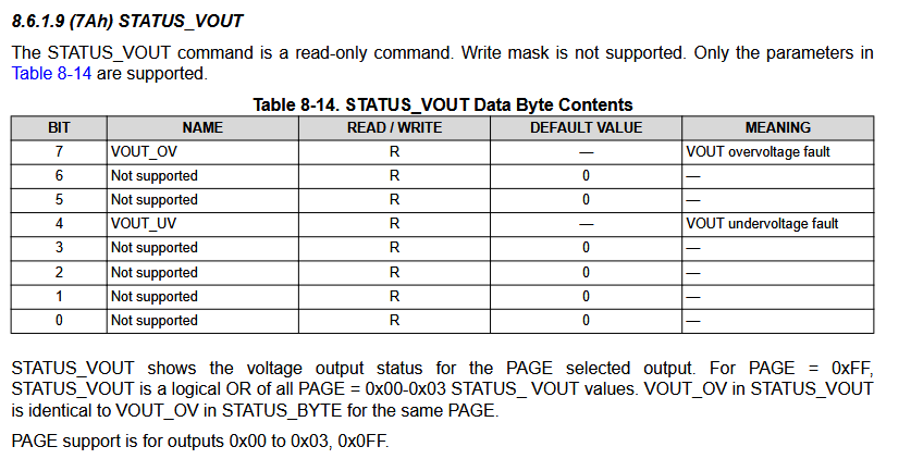
I tried reading STATUS_VOUT to see if it’s showing an under or overvoltage error, but it is always at 0.
The next most useful register looks to be STATUS_BYTE:
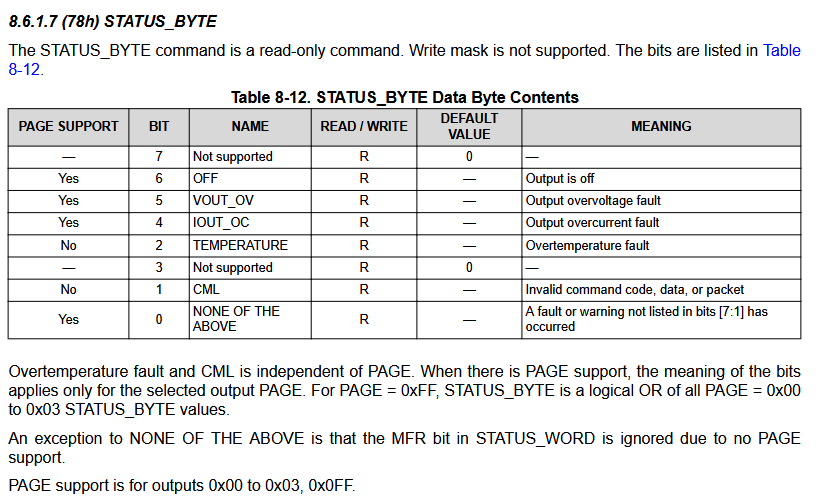
During reset, this register reads 1010011. Meaning:
- The output is off
- Overcurrent fault
- Something else too
Checking the IOUT_MAX register(after setting page=0), I get 1, meaning a 3A current limit is set for output 1:

Let’s try and set 5A and see what happens.
Wire.beginTransmission(0x69);
Wire.write(0xD9);
Wire.write(0b100);
Wire.endTransmission();
Even after doing this, the register stays at 1, meaning 3A. A reset doesn’t help either. Looking further into the datasheet, there is a WRITE_PROTECT register.
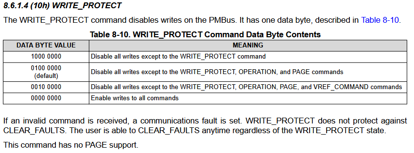
I tried writing any of the values listed in the datasheet, but no matter what I did, it stayed on 1000000.
However, I did attempt to change the current limit again, and surprisingly, it worked! Let’s try running the DPU example again on the Arty.
-----------------------------
Class name: bicycle     [ID]:1
-----------------------------
Class name: truck     [ID]:7
-----------------------------
Class name: dog     [ID]:16
Woo! It works. We can now use the DPU to accelerate inference.
Back to the PMIC, as we need to save the new current limit. I ended up setting it to the maximum(6A), just to make sure. I'm not 100% sure this is a great idea, but whatever.
To save to the built-in flash, all that’s needed is writing to address 0x11.
Here's the entire Arduino code that disables write protection temporarily, selects page 0 (essentially tells the PMIC that we want to configure / get data from SW1), and sets the current limit to 6A
#include <Arduino.h>
#include <Wire.h>


void setup() {
  Serial.begin(9600);
  Wire.begin();
  delay(100);

  // Select page 0
  Wire.beginTransmission(0x69);
  Wire.write(0x00);
  Wire.write(0x00);
  Wire.endTransmission();
  delay(100);

  // Disable protection
  Wire.beginTransmission(0x69);
  Wire.write(0x10);
  Wire.write(0x00);
  Wire.endTransmission();
  delay(100);

  // set 6A current limit for SW1
  Wire.beginTransmission(0x69);
  Wire.write(0xD9);
  Wire.write(0b00000100);
  Wire.endTransmission();
  delay(100);

  // Save settings
  Wire.beginTransmission(0x69);
  Wire.write(0x11);
  Wire.endTransmission();

  delay(5000);
}

byte lastStatus = 0;
void loop() {
  // Read current limit
  Wire.beginTransmission(0x69);
  Wire.write(0xD9);
  Wire.endTransmission(false);
  Wire.requestFrom(0x69, 1);
  byte status = Wire.read();

  if(status != lastStatus) {
    Serial.print("Current limit: ");
    Serial.println(status, BIN);
    lastStatus = status;
  }
}
And with that, the board is fixed. I disconnected both the Arduino and Arty from everything, and plugged the Arty back to see if the fix still works.
root@dpu_petalinux:~/yolo_pynqz2# ./yolo_image dog.jpg
-----------------------------
Class name: bicycle     [ID]:1
-----------------------------
Class name: truck     [ID]:7
-----------------------------
Class name: dog     [ID]:16
Yep! Everything is working as it should.
Conclusion
With the DPU and Arty now working, a custom model can be trained and converted to run on the DPU. With that ready, all that’s left is writing some code to process the results and issue audiovisual warnings and alerts to the driver.
The Arty issues took a lot of time to troubleshoot and fix, so I’m a bit behind on this project, but hopefully I can get everything ready in time.
References
https://andre-araujo.gitbook.io/yolo-on-pynq-z2
https://github.com/wutianze/dnndk-pynqz2
http://www.aiotlab.org/teaching/fpga/DPU%20on%20PYNQ-Z2_Vivado.pdf
