Introduction
The main idea is create an image processor for feature enhancement on the live acquisition from a microscope. The first stage is create a general purpose image processor with classical techniques and continuos system improving. Most of the required material are shown in the image above, all the materials provided and some additional peripherals in the Pmod connection to reduce the complexity. On the other hand, if it is required additional hardware, it must be added to the project.
The main objective of Metallography, as a science, is analyze and take decisions about the constitution and structure of metals and alloys. This is done in order to get the quality or especial functionalities of materials. According to ASM, the analisys could be in low magnification in optical microscopes from 20x, and raising up to 1,000,000x in electron mycroscopes. The actual project has interest in optical approach to adapt a microscope HMDI output to enhance features in the image acquisition and processing.
| {gallery}mSamples |
|---|
|
IMAGE TITLE: THEN IMAGE DESCRIPTION |
|
IMAGE TITLE: THEN IMAGE DESCRIPTION |
|
IMAGE TITLE: THEN IMAGE DESCRIPTION |
|
IMAGE TITLE: THEN IMAGE DESCRIPTION |
The images avobe were acquired with a general purpose microscope with incident polarized light source. according to the polarization angle, some features could be improved or visible and all these features require a clasification and enhancement to make decisions about the uses of the materials. In this case, the camera output, which is HDMI, will be inserted on the board and the output must be visualized in a dedicated monitor to mount an analisys terminal
Tests
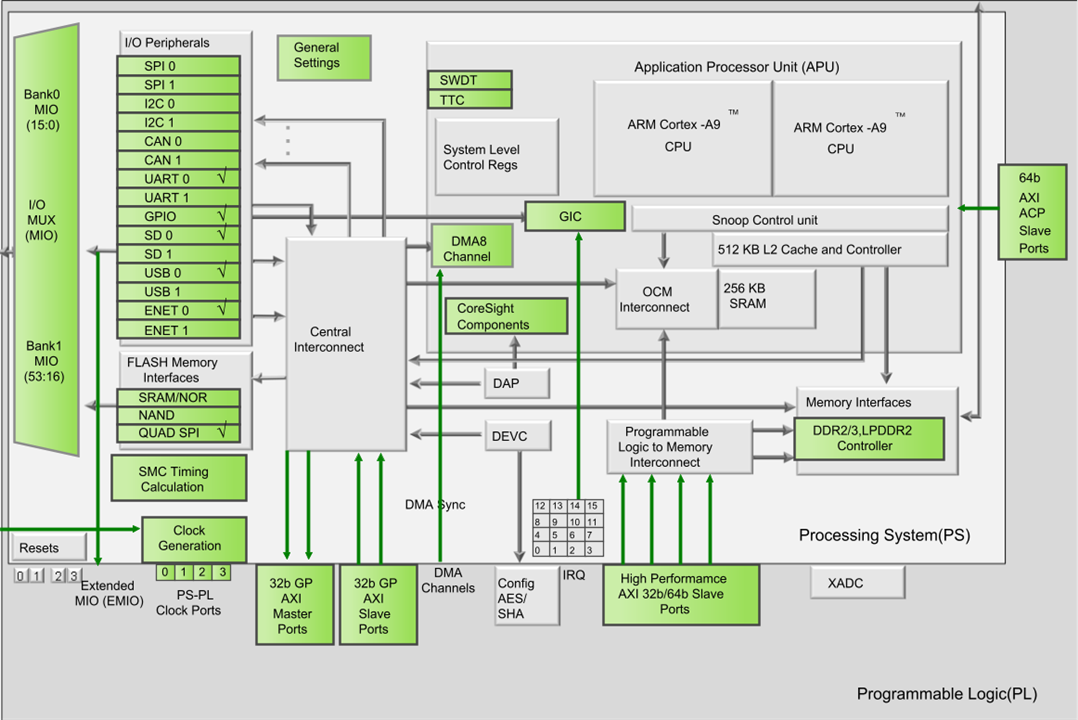
An initial test of the board is using only the Hard Processor (HP). This device contains a rich peripheral system, it has UART, USB, Ethernet and more peripherals available to operate without the Programmable Logic (PL) assistance.

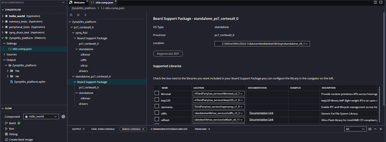
For the actual project the PL interface is not required, consequently, the PL Fabric Clock is deactivated and the Master AXI interface is deactivated also. It is needed verify the connection of UARTx in order to communicate to the computer. Nowadays, the Vitis software has a new interface and the drivers had been updated. The Classical Vitis is deprecated and will be removed in future releases. This means that the last interface must be used for new designs. This interface create componens one-by one, an important difference with the classical where the platform and application could be created on the same process.
The creation of the plarform brings a set of files, and like other projects this must be compiled in order to have a functional architecture for software implementation. You are able to review the Board Support Package to get more information about the supported libraries and examples to use.

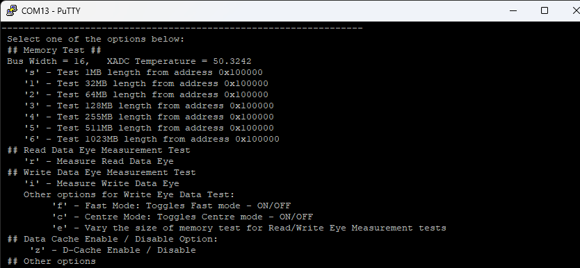
This time I created a zynq_dram_test project from the examples available, this in order to test the 512 MB of DDR3 RAM included in the board. If you try to write the program directly in the board, you must get Memory read error at 0xF8F00208. Cannot halt processor core, timeout. Because the board load the connections from the QSPI, we are not able to test the hard processor in the Vitis software. To solve it, the QSPI jumper must be removed and set in the JTAG option.

After continuous test in the DRAM in the option 5, which made a test over 511 MB of RAM, the board raised up its temperature. This conducted to me for the consideration of mount an temperature dissipator. The board reached about 50°C, this could limitate the behavior of the final project and we are made more test in order to avoid unspected operations.

Another test was based on the output of HDMI. In order to test the usage and HDMI port functionality, the example provided of the HDMI output was updated to the 2024.1 version of the development platform. Unfortunately, the software requires mayor revisions for the usage in the Vitis 2024.1, consequently, the Vitis Classic 2024.1 was used for this test. A Mandelbrot set pattern generator was used for the visualization in a monitor. The pattern generator uses the following code.
xil_printf("Newest Pattern\n");
static _Complex zn, C;
center = 2*width/3 + height/2*I;
unsigned int n = 0;
for(u32 c = 0; c < width; c++){
	iPixelAddr = 3*c;
	for(u32 r = 0; r < height; r++){
		zn = 0 + 0*I;
		n = 0;
		C = ((c + r*I - center))/250;
		while((cabs(zn) < 2) & (n < 20)){
			zn = cpow(zn, 21) + C;
			n++;
		}
		frame[iPixelAddr] = 51*(n%5);
		frame[iPixelAddr + 1] = 12.75*(20 - n);
		frame[iPixelAddr + 2] = 12.75*n;

		iPixelAddr += stride;
	}
}
Xil_DCacheFlushRange((unsigned int) frame, DEMO_MAX_FRAME);
In this case, the complex header file must be added and link the math ABI for the correct usage of the code block. The code was added in one of the cases of the pattern generator, and the output, which was captured with a USB converter, is shown below.
This test bring some ideas of the platform capacity and possible challenges to take in account to solve the data processing algorithms required for the feature enhancement in the microscope camera.

-

dougw
-
Cancel
-
Vote Up
0
Vote Down
-
-
Sign in to reply
-
More
-
Cancel
-

pandoramc
in reply to dougw
-
Cancel
-
Vote Up
0
Vote Down
-
-
Sign in to reply
-
More
-
Cancel
Comment-

pandoramc
in reply to dougw
-
Cancel
-
Vote Up
0
Vote Down
-
-
Sign in to reply
-
More
-
Cancel
Children