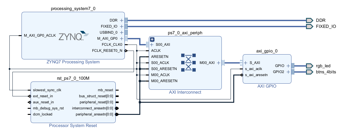
Sometimes it is neccessary to use of soft components in order to meet specific processing tasks. In this scenario, the interface with the RGB Leds and buttons for data capture and software based behavior synthesis is implemented to test an AXI peripheral. An AXI GPIO solves the commented situation, we take the information generated from an external interface, process it through software, and create a physical phenomenon. Not only adding the peripheral solves an specific problem, but it is necessary to know the memory location for data sharing between the Hard-Processor (HP) and the Programmable Logic (PL). As shown in the architecture above, the PS generates reset states and clock source to synchronize al the logic elements involved. Moreover, a communication referee is also required. For this, the AXI matrix interconnect is the mosr feasible interface for the connection between the processor and the peripheral. On the other hand, the processor system has its own fixed ports DDR memory and IO interfaces.
For the platform testing, an arbitrary example meets the requirements to debug the interface since we are able to make hot programming if the peripheral without the defined software. This allows us to take advantage of the known architecture and make changes to the memory and see the effects over the datapath in the hardware.
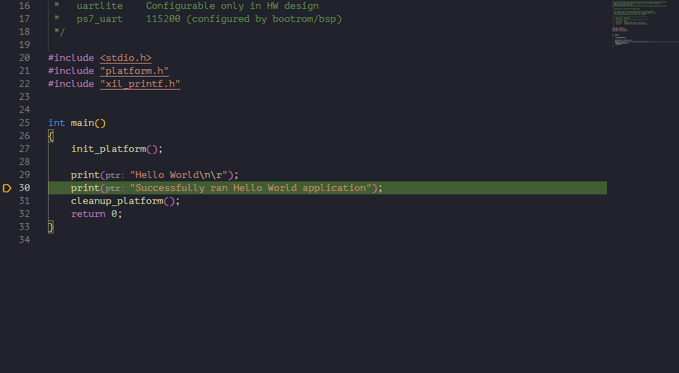
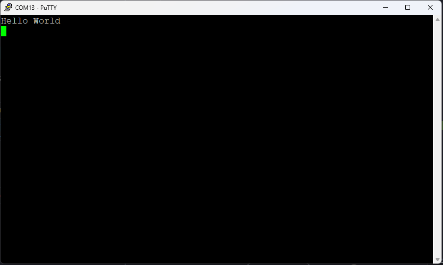
Regardless of the base code, in this exercise the hello world example is used to debug the platform. For the general purpose testing, we are able to pause the execution and create a memory viewer interface to visualize and edit memory contents.
| {gallery}My Gallery Title |
|---|
|
Putty Console: Hello world application paused |
|
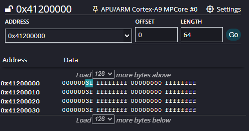
Memory Viewer: Base address of AXI GPIO |
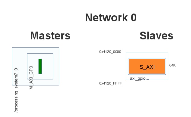
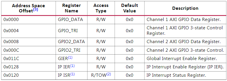
For the actual purposes is required the memory map pf the peripheral and the meaning of each bit. Each external element uses a bit that could be input, for buttons or switches, or output, for each LED connected to the port. Since the base address of the peripheral is 0x41200000, the memory viewer must be located on that value. This auxiliary memory pointer allows reading and writing of the values of each word available word in the memory. If the memory address is not reached for architecture limitations, the debugger will notify that there is no data to show, but this will not cause errors like writting code to an invalid memory address.
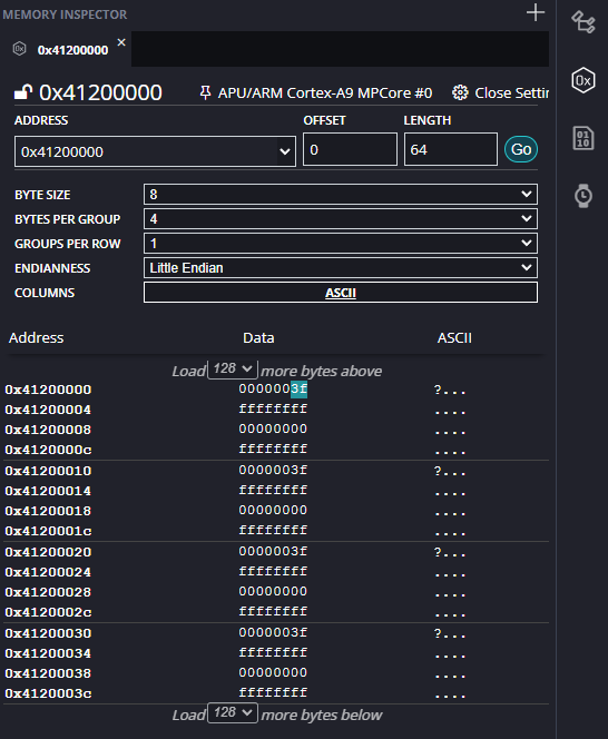
The implemented AXI GPIO has dual configuration, one for outputs and one for inputs. Here, the developer is able to read the values from the buttons and write data to the RGB LEDs. On the other hand, the developer, in a hot write way, can configure the memory viewer to improve the data visualization and edition. The modification of the peripheral behavior does not requires the processor in running state since the peripheral is core independent. Most of the actual architectures have a Little Endian data storage, consequently, this configuration should be applied in the viewer. A 0x00 write in the Least Significant Byte (LSB) will clear the data and this is illustrated with the LEDs in off state. In order to turn on a LED, a One must be written in the corresponding bit, for example, the value 0x14 will activate the green LED (LD5) and the red LED (LD4).
| {gallery}Hot write |
|---|
|
Memory Viewer: Little Endian Word Configuration |
|
Architecture Viewer: Register Map |
|
AXI GPIO Memory Map: AXI GPIO Memory Map |
Once the behavior is validated, the developer is able to read or write to the peripheral registers. The header file xil_io.h contains interfaces for general purpose I/O on the peripherals. If the user knows the base address of the peripheral, he/she can write or read the data available in the registers. In order to avoid misunderstandings about the peripheral location, the xparameters.h header file contains all the peripherals, hard or soft, base addresses. This results in the following sample code,
#include <xil_io.h>
#include "xparameters.h"

int main(void){
    uint32_t btnIn;
    uint32_t ledState;
    while(1){
        ledState = Xil_In32(XPAR_AXI_GPIO_0_BASEADDR);
        btnIn = Xil_In32(XPAR_AXI_GPIO_0_BASEADDR + 8);
        if(btnIn & 0x08){
            ledState &= ~0x07;
            ledState |= (btnIn & 0x07);
        }else{
            ledState &= ~0x38;
            ledState |= (btnIn & 0x07) << 3;
        }
        Xil_Out32(XPAR_AXI_GPIO_0_BASEADDR, ledState);
    }
}
The code above has the feature of the LED selection to modify the color representation of the data. In addition to it, the user can interact through the button panel and modify the color in accordance.
Once the architecture is understood, the developer can implement a new software abstraction layer to simplify the hardware access for data sharing. This will be implemented and improved in the next blog.

