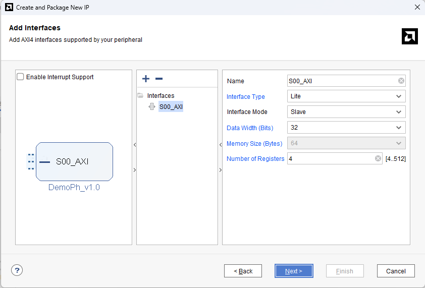
The IP catalog is really wide in terms of logical blocks with AXI interface for system integration with the Hard Processor (Zynq7) or Soft Processor (Microblaze V). In the last blog, an AXI GPIO was integrated to share data between the HP and the Programmable Logic (PL), but sometimes the required behavior could not meet the specifications with the available AXI catalog. With this in mind, it is necessary to design our custom logic with an interface to the processor for configuration and data transfer in the both devices. This brings us to the use of the Create and Package New IP, available in the Tools menu. For our purposes, the Create a new AXI4 peripheral is selected since our project will not be a part of a new IP as a whole, but a new device will be added to the current project. To achieve a device compatibility, the data width must be 32-bit, but a 64-bit interface could be used according to the architecture. On the other hand, the new IP will work according to the configuration registers, consequently, a Lite Slave interface is chosen because the communication between the processor and the soft peripheral is not a high priority.
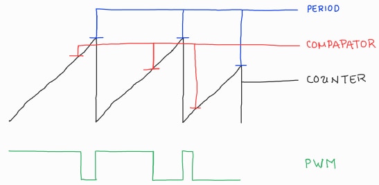
For this process, a PWM generator will be created and only will only have the behavior of a counter until the PERIOD value is met, and a COMPARATOR register generates a high state when the counter starts, and a low state when a comparison occurs. Finally, the processor is able to query the COUNTER value to monitor the process, but the interface does not allow writing to the register. The described behavior is as follows,
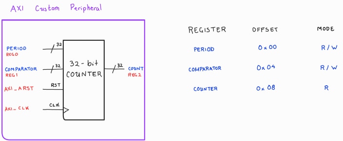
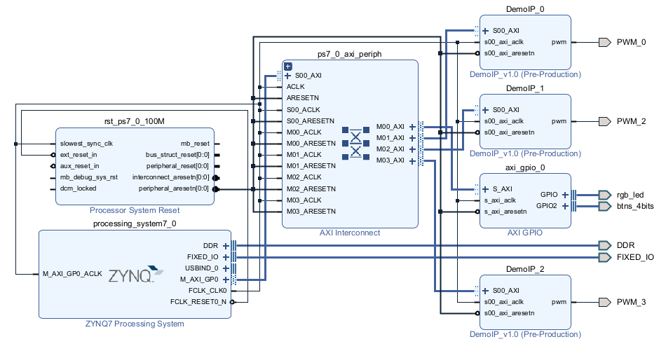
As the image shows, the frequency and duty cycle are configured by the writing to the PERIOD and COMPARATOR registers, but this is not possible directly. In the first step, the logic must be described and connected to the logic communication from an AXI4 interface, which is created from the IP wizard, and the interfaces must be instantiated at the appropriate location. A high level view is shown below, where an instance of our logic block is created and the wiring is made by the available registers in the template. According to our configuration, the DemoIP block is created with 4 memory locations, which is the minimum configurable in the IP wizard, for the data storage and behavior configuration of the behavior. Remember! the addressing is Byte wide, but the data width is 32 bits, consequently, the memory offset is in multiples of four Bytes.
In this case, the PWM generator has the following description,
module pwm_gen (
	input aclk,
	input resetn,
	input [31:0] period,
	input [31:0] comparator,

	output reg [31:0] counter,
	output pwm
);

	always @(posedge aclk)
		if (!resetn)
			counter <= 0;
		else
			if (counter < period)
				counter <= counter + 1;
			else
				counter <= 0;

	assign pwm = (comparator > counter)? 1'b1: 1'b0;

endmodule
Once the IP is packaged, the user can create many instances as the logic resources are available. For the newest platform, the DemoIP will be instantiated three times.
Since the PWM_n terminals are not available in the default configuration, this terminal must be configured with a XDC file. Here, the pins are configured in two Arduino terminals and one in the LED0 to validate the configuration visually.
set_property -dict { PACKAGE_PIN R14    IOSTANDARD LVCMOS33 } [get_ports { PWM_0 }]; #IO_L6N_T0_VREF_34 Sch=LED0
set_property -dict { PACKAGE_PIN T15   IOSTANDARD LVCMOS33 } [get_ports { PWM_2  }]; #IO_L5N_T0_34            Sch=CK_IO5
set_property -dict { PACKAGE_PIN R16   IOSTANDARD LVCMOS33 } [get_ports { PWM_3  }]; #IO_L19P_T3_34           Sch=CK_IO6
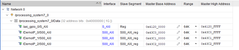
Finally, the Base Address for Custom IP, by default, starts in the address 0x43C00000. On the other hand, the AXI GPIO holds the provided base address from the last project. Below, the memory map is shown.
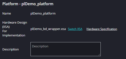
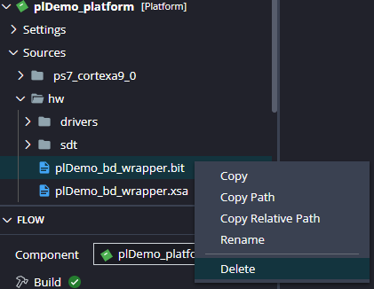
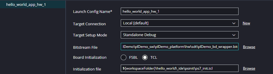
Before the programming of a new application, the platform must be updated in the Vitis Unified IDE. To do it, the first step is change of the XSA platform definition. When the hardware is exported in Vivado, all the definitions and the newest .bit file is grouped for the platform definition, but Vitis has a bug and the XSA swithching is not sufficient enough to redefine the architecture. The second step is remove the current bit file from the Sources>hw Vitis component, and import the last synthesis of the architecture available in the PROJECT.runs folder from the Vivado project. When the last step is made, clean and compile the Platform component. This will create the new export folder where the .bit file is available in the last version. Finally, the Application component launch.json must be updated to use that bit file, now we know the file location in the platform and the Bitstream File field must be updated.
| {gallery}Update Process |
|---|
|
Switch XSA: Update the platform definition |
|
Bitstream replacement: Delete the current Bitstream and import the newest |
|
Bitstream File location: Update the Bitstream location in the Application component |
|
Bitstream verification: If the Bitstream replacement is success, then the files must not differ |

In the software perpective, we can create a pair of files PWMGen.c and PWMGen.h for the configuration management. Here, there are two perspectives for configuration, Time and Duty Cicle. For the frequency configuration, we only need the relationship between the AXI frequency and the desired Frequency, consequently, the PERIOD register must be configured as,
![]()
and the COMPARATOR register has two methods: the duty, using a percentage of the PERIOD register, and time, the relationship between the desired time and the AXI clock. All methods and test can be viewed in the codes below
#ifndef __PWMGEN_H__
#define __PWMGEN_H__

#include <xil_types.h>

void DemoFrequency(UINTPTR Addr, u32 Frequency);
void DemoDuty(UINTPTR Addr, float percent);
void DemoTime(UINTPTR Addr, float time);

#endif
#include "PWMGen.h"
#include "xparameters.h"
#include <xil_types.h>

#ifndef FCPU
#define FCPU 100000000UL
#endif

void DemoFrequency(UINTPTR Addr, u32 Frequency){
    u32 Period = FCPU/Frequency;
    *((volatile u32 *)Addr) = Period;
}

void DemoDuty(UINTPTR Addr, float percent){
    u32 Comparator = percent*(*((volatile u32 *)Addr));
    *((volatile u32 *)(Addr + 4)) = Comparator;
}

void DemoTime(UINTPTR Addr, float time){
    u32 Comparator = time*FCPU;
    *((volatile u32 *)(Addr + 4)) = Comparator;
}
#include <xil_io.h>
#include <xil_types.h>
#include "xparameters.h"
#include "PWMGen.h"

int main(void){
    uint32_t btnIn;
    uint32_t ledState;

    DemoFrequency(XPAR_DEMOIP_0_BASEADDR, 1);
    DemoDuty(XPAR_DEMOIP_0_BASEADDR, .5);

    DemoFrequency(XPAR_DEMOIP_1_BASEADDR, 50);
    DemoTime(XPAR_DEMOIP_1_BASEADDR, 1e-3);

    DemoFrequency(XPAR_DEMOIP_2_BASEADDR, 1000);
    DemoDuty(XPAR_DEMOIP_2_BASEADDR, .75);

    while(1){
        ledState = Xil_In32(XPAR_AXI_GPIO_0_BASEADDR);
        btnIn = Xil_In32(XPAR_AXI_GPIO_0_BASEADDR + 8);
        if(btnIn & 0x08){
            ledState &= ~0x07;
            ledState |= (btnIn & 0x07);
        }else{
            ledState &= ~0x38;
            ledState |= (btnIn & 0x07) << 3;
        }
        Xil_Out32(XPAR_AXI_GPIO_0_BASEADDR, ledState);
    }
}
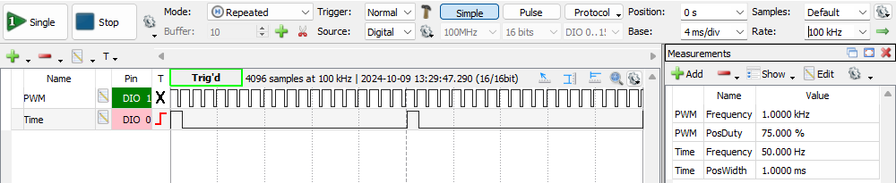
The main code holds the beavior implemented in the last blog and the methods generates the waveforms below, proving the implemented code reflects the mathematical and logic reasoning to bring a Hardware Abstraction Layer (HAL) for our Custom IP