


The PYNQ (Python Productivity for Zynq) Framework
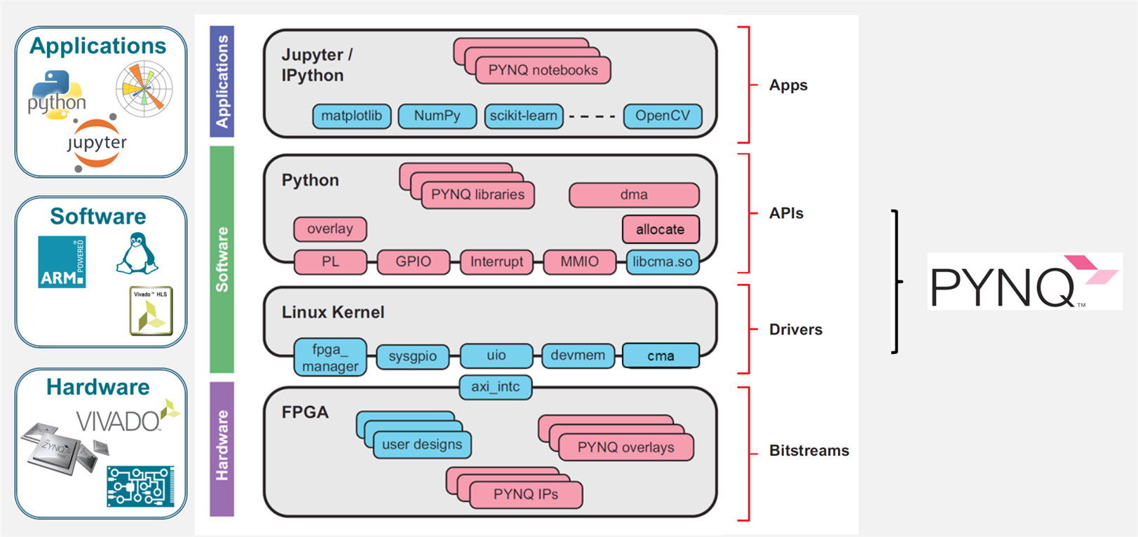
PYNQ overlays use a combination of .bit, .hwh, and optionally .tcl files to reconfigure the programmable logic (PL) on a Xilinx Zynq SoC and provide a seamless interface for Python-based interaction with the hardware. Here's a detailed breakdown of how each file plays a role:
1. .bit File: The Bitstream
- Purpose:
The.bitfile contains the binary configuration data for programming the FPGA (PL). It is generated during the hardware design flow in Vivado and defines the placement and routing of logic elements, interconnects, and other resources in the PL. - Role in PYNQ:
When an overlay is loaded in PYNQ, the.bitfile is used to configure the FPGA hardware design into the PL:from pynq import Overlay overlay = Overlay("/path/to/your/overlay.bit")- This step reconfigures the PL to match the desired hardware architecture.
- The
.bitfile defines the physical behavior of the hardware but does not expose its structure to Python directly.
2. .hwh File: Hardware Handoff
- Purpose:
The.hwhfile is an XML-like metadata file generated alongside the.bitfile by Vivado. It describes the hardware design's internal structure, including:- AXI interfaces.
- Address maps.
- Clock connections.
- Configuration registers of hardware IPs.
- Role in PYNQ:
- PYNQ uses the
.hwhfile to parse the hardware's architecture and automatically map the hardware IPs to Python objects. - For example, when you access
overlay.axi_dma, PYNQ knows how to interact with the AXI DMA IP block because the.hwhfile provides its address map and interface details. - Without the
.hwhfile, you would need to manually provide these details, making the design less user-friendly.
- PYNQ uses the
3. .tcl File: Tcl Script (Optional)
- Purpose:
The.tclfile is a Vivado script that describes how the hardware design was constructed. It includes:- The IP block configurations.
- Connections and parameters.
- Design constraints.
- Role in PYNQ:
- The
.tclfile is optional and not directly used by PYNQ at runtime. However, it is helpful during the development or debugging process for regenerating or modifying the Vivado project. - It can also be used for advanced workflows, such as modifying an overlay dynamically or automating FPGA design customization.
- The
How These Files Work Together:
-
Development in Vivado:
- You design the hardware, integrate IP cores, configure interfaces, and generate the
.bitand.hwhfiles. - Optionally, you generate the
.tclfile for reproducibility or further customization.
- You design the hardware, integrate IP cores, configure interfaces, and generate the
-
Overlay Creation:
- The
.bitand.hwhfiles are packaged together as an overlay for use in PYNQ.
- The
-
Loading the Overlay:
- The
.bitfile configures the PL with the desired design. - The
.hwhfile allows PYNQ to understand the design, automatically map hardware IPs, and provide a Python API for interacting with them.
- The
-
Python Integration:
- PYNQ abstracts the hardware details using the
.hwhmetadata. Users can control the hardware from Python without needing low-level details:dma = overlay.axi_dma # Access the AXI DMA block dma.sendbuffer # Start sending data through DMA - The
.hwhfile enables these high-level Python APIs to interact seamlessly with the hardware.
- PYNQ abstracts the hardware details using the
Why is This Powerful?
-
Dynamic Reconfiguration:
Overlays can be swapped dynamically by loading different.bitfiles during runtime, making PYNQ versatile for multiple applications without rebooting. -
Ease of Use:
The.hwhfile removes the need for manual address mapping and register configuration, providing Python libraries that abstract complex FPGA interactions. -
Rapid Prototyping:
By combining these files with Python, PYNQ enables hardware acceleration for complex applications with minimal overhead in software and hardware integration.
This approach streamlines FPGA development, making it accessible even for software developers unfamiliar with low-level FPGA programming.
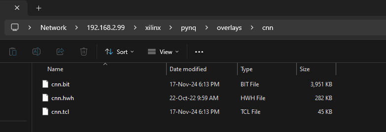
The Bitstream, Hardware handoff, and the TCL file for the block design are placed inside a newly created directory in Overlays directory.
How is the overlay programmed?
-
Communication with FPGA:
- The Zynq SoC includes an ARM processor (PS) that communicates with the FPGA fabric (PL) via a programming interface.
- The PYNQ framework uses the Xilinx FPGA Manager (or a similar driver) to send the
.bitfile from the Linux filesystem to the FPGA's configuration memory.
-
Configuration Memory Programming:
- The
.bitfile is streamed to the FPGA configuration memory through the Configuration Access Port (CAP). - This process resets the PL and configures it with the new hardware design.
- The
-
Verification and Completion:
- After programming, the FPGA reports a "done" signal to confirm successful configuration.
- If an
.hwhfile is present, it is parsed to map the hardware design's interfaces to Python objects.
The process is dynamic, meaning overlays can be swapped at runtime without rebooting the system.
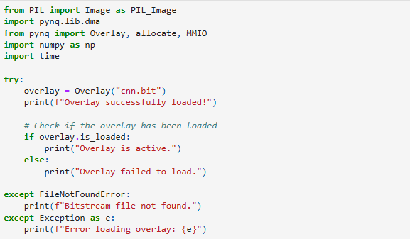
Given below is snipped that programs the custom overlay into the PL of Zynq
1. Loading the FPGA Bitstream
overlay = Overlay("cnn.bit")
print(f"Overlay successfully loaded!")
Overlay("cnn.bit"): Loads the specified bitstream file (cnn.bit) onto the FPGA. This file contains the hardware design for your CNN accelerator.overlay: Represents the loaded bitstream and provides access to its components (DMA engines, MMIO registers, etc.).- The print statement confirms that the overlay was loaded successfully.
2. Checking Overlay Status
if overlay.is_loaded:
    print("Overlay is active.")
else:
    print("Overlay failed to load.")
overlay.is_loaded: Checks whether the overlay has been successfully loaded onto the FPGA.- If the bitstream is loaded and active, it prints confirmation. Otherwise, it indicates failure.
3. Error Handling
except FileNotFoundError:
    print(f"Bitstream file not found.")
except Exception as e:
    print(f"Error loading overlay: {e}")
FileNotFoundError: Triggers if the specified bitstream file (cnn.bit) is not found in the working directory or specified path.Exception: Catches any other errors that may occur during the bitstream loading process and prints the error details.
Next, the same array used in Vitis IDE/Xilinx SDK to test the CNN HW accelerator is added as a python list.
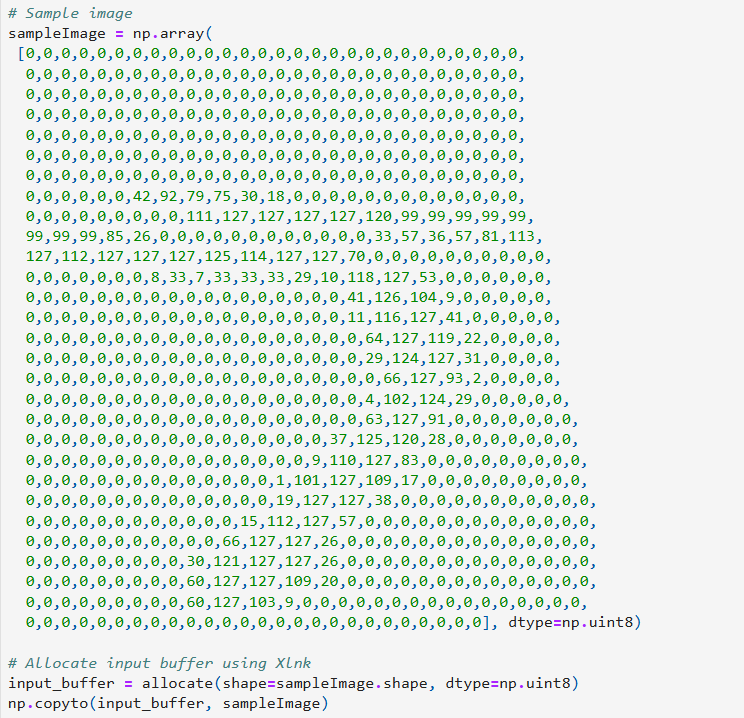
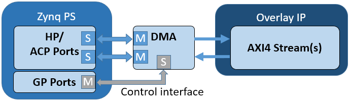
Using DMA to transfer the data into our custom IP
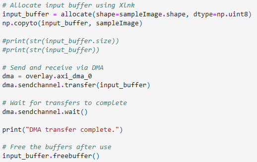
1. Input Buffer Allocation
input_buffer = allocate(shape=sampleImage.shape, dtype=np.uint8)
np.copyto(input_buffer, sampleImage)
allocate: Allocates a physically contiguous buffer in memory to be used for DMA transfer. This is critical for FPGA-to-CPU communication, as DMA requires contiguous memory regions.np.copyto: Copies the data from the preprocessed image (sampleImage) into the allocated buffer.- The buffer's shape and data type (
uint8) match the input data.
Note: sampleImage should already be resized and preprocessed (e.g., the 28x28 MNIST image).
2. DMA Transfer to the Accelerator
dma = overlay.axi_dma_0
dma.sendchannel.transfer(input_buffer)
dma.sendchannel.wait()
print("DMA transfer complete.")
overlay.axi_dma_0: Refers to the DMA instance configured in the FPGA bitstream (overlay.bit).dma.sendchannel.transfer(input_buffer): Initiates the transfer of data from the allocated input buffer to the hardware accelerator via the DMA engine.dma.sendchannel.wait(): Waits for the DMA transfer to complete before proceeding.
3. Freeing the Input Buffer
input_buffer.freebuffer()
- After the transfer is complete, the input buffer is freed to release the allocated memory.
4. Output Data Retrieval
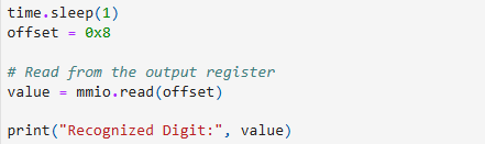
time.sleep(1)  # Small delay to ensure processing completion
offset = 0x8
value = mmio.read(offset)
print("Recognized Digit:", value)
time.sleep(1): Introduces a delay to allow the accelerator sufficient time to process the input data.offset = 0x8: Specifies the register offset for reading the output of the accelerator. This value depends on your hardware's register map.mmio.read(offset): Reads the result (recognized digit) from the specified register.value: Contains the recognized digit output by the accelerator.
Read AXI MMRs in PYNQ
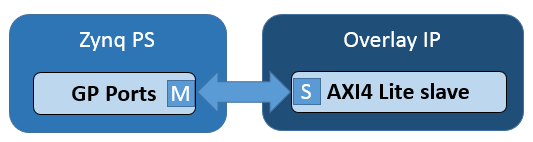
To read an MMIO (Memory-Mapped I/O) register in PYNQ, you can use the pynq.MMIO class. Here's a step-by-step guide:
1. Import the Required Module
from pynq import MMIO
2. Identify the MMIO Address and Size
- You need the base address and the size of the MMIO region. These are typically provided in the hardware specification (e.g., from a block design in Vivado).
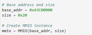
3. Create an MMIO Instance
Initialize an MMIO object with the base address and size:
mmio = MMIO(base_addr, size)
- Replace
base_addrwith the starting physical address of the MMIO region. - Replace
sizewith the size of the MMIO region in bytes.
4. Read from an MMIO Register
To read a value from a specific offset within the MMIO region:
value = mmio.read(offset)
- Replace
offsetwith the register's offset (in bytes) from the base address.
Give some time for CNN accelerator to complete processing.
Output
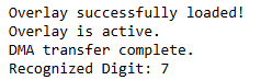
This output is expected (refer to the previous blog, where C was used to perform the same operation)
