Introduction
In this blog, I will bring up the Arty Z7 board and load some custom HDL design onto it using the Vivado Design suite.
What is Vivado?
Vivado Design Suite is a software suite developed by AMD for synthesis and analysis of hardware description language designs. It is an IDE with system-to-IC level tools. It is primarily used for FPGA and SoC development.
What tools does Vivado Design Suite offer?
Vivado Design Suite offers a comprehensive set of tools for FPGA and SoC design. Some of the features are:
- Design: We can create our own designs using HDL (Hardware Description Language), block diagrams, or high-level synthesis.
- Synthesis: Coverts the design into netlist and optimizes it.
- Place & Route: Maps the netlist into physical FPGA.
- Simulation: Verify the functionality of the design before implementing it on the FPGA.
- Debugging: Debug and analyze designs to make sure they follow the specifications.
- IP Integration: Facilitates integration of various IP blocks into our design.
Components of Vivado Design Suite.
Vivado also has some high-level design tools like Vitis HLS for C, C++ and SystemC synthesis and IP integrator.
- Vitis HLS: The High Level Synthesis compiler enables C, C++ & SystemC programs to be directly targeted into Xilinx devices without the need to manually create RTL.
- Vivado Simulator: It is a compiled-language simulator that supports mixed-language, tcl scripts, encrypted IP and enhanced verification.
- Vivado IP integrator: It allows us to quickly integrate and configure IP from the large Xilinx IP library.
- Vivado TCL store: It is a scripting system for developing add-ons to Vivado, and can be used to add and modify Vivado's capabilities.
Getting Started with the Arty Z7 board
In this section, I will plug in the board to the laptop and step by step go through the process of loading the program onto the board.
Requirements:
- Arty Z7 board
- Vivado Design Suite Installed
- USB Cable
To make sure that the board is working fine, I plugged it into the laptop using the USB cable. The preloaded program started running and the LEDs started blinking, that means the board is working fine.
Now, I can start building the project. This will be a simple project to make sure that the overall flow is working and I am not missing any drivers or other components. In this project, I will try to control the onboard LEDs with the buttons present on the board. This requires a little knowledge of HDL languages (like verilog, vhdl) and luckily I have that. I will use verilog for this project.
- Create a new project in Vivado. Give a project name and location.

- In the next window, select the type of project as RTL project.
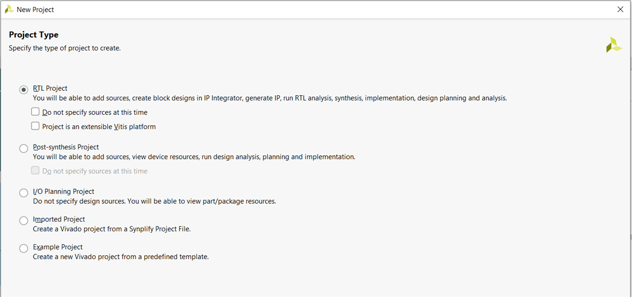
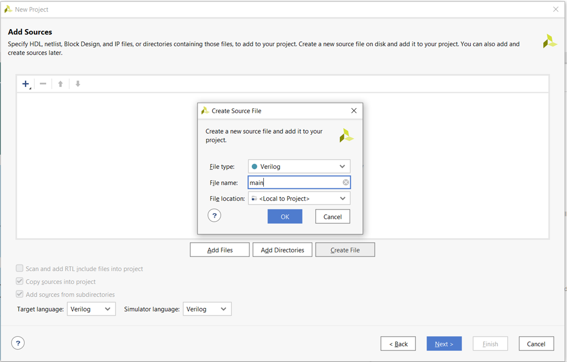
- Now, we will create a source file which will contain the RTL code. For that click on 'Create File'. A new window will open. Enter the file name and press ok. Then click on Next.
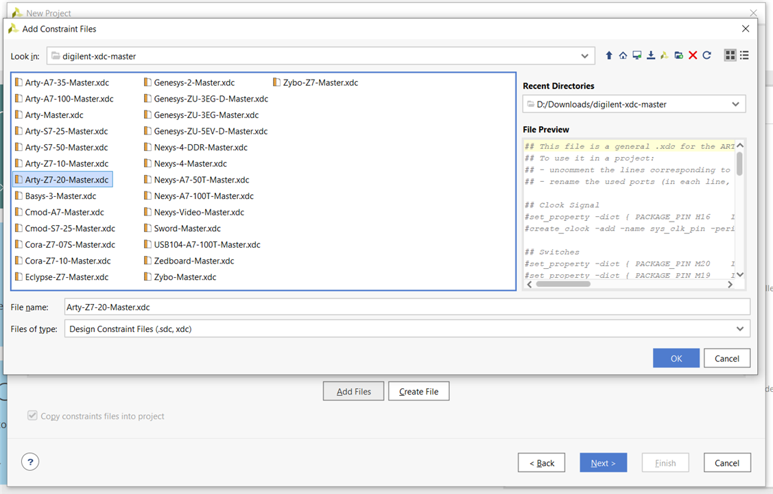
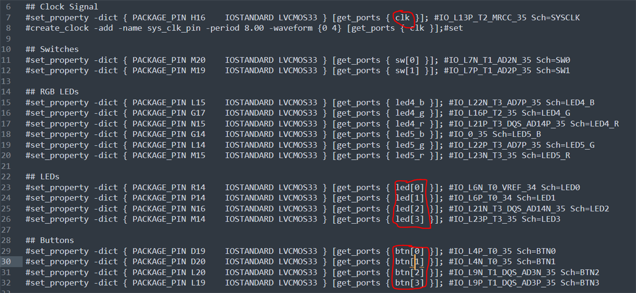
- Now, we will add the constraint file. The constraint file will be required to interface with the LEDs & Switches present on the board. Constraint files for Digilent boards can be downloaded from this link.
- Click on 'Add Files' in the new window. And select the proper constraint file according to the board. In my case, it is Arty-Z7-20-Master.xdc. Click on Next.
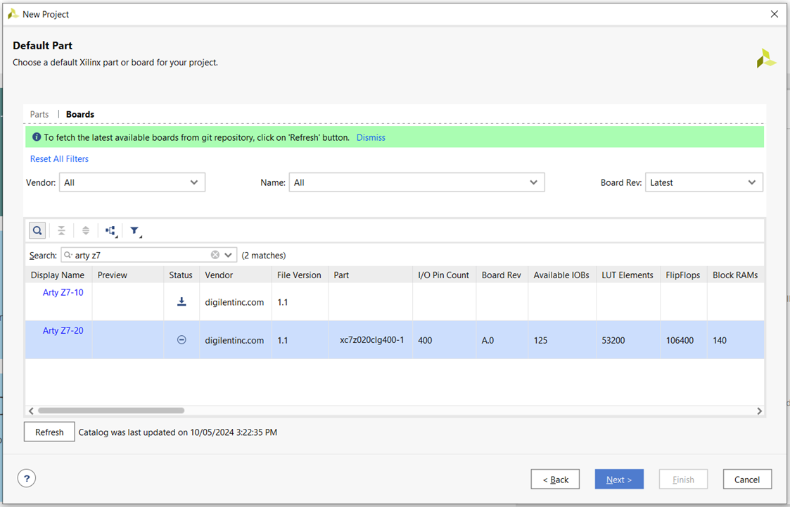
- Now, we will select the part number of our board. In the 'Default Part' window, select the 'Boards' tab. Click on the 'Refresh' button to get latest boards available from the repository. Select the proper board. I am selecting Arty Z7-20. One can also search for the board in the search bar. Install the board by clicking on download button in the 'Status' column if it is not already installed. Then click on next.
- Confirm the details in the project summary window. Then click on 'Finish'.

- It may take a few seconds to create the project.
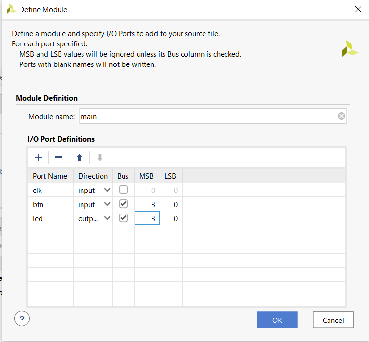
- After the project is created, a window will appear and it will ask to define the module. We can change the module name or keep it as default. We will need some input & output signals to get the clock and send output control signal to the LEDs.
There is one important thing to note. The signal names we are using must be the same as those defined in the constraint file. Here I have used the same names which are there in the constraint file by default. But if anyone wants to use different name, they can change the name in the constraint file and then use those in their module.
- 'clk' to get the input clock.
- 'btn[3:0]' 4 bit input signal to get the status of the onboard buttons. Each single bit represents one button.
- 'led[3:0]' 4 bit output signal to send signals to the LED.
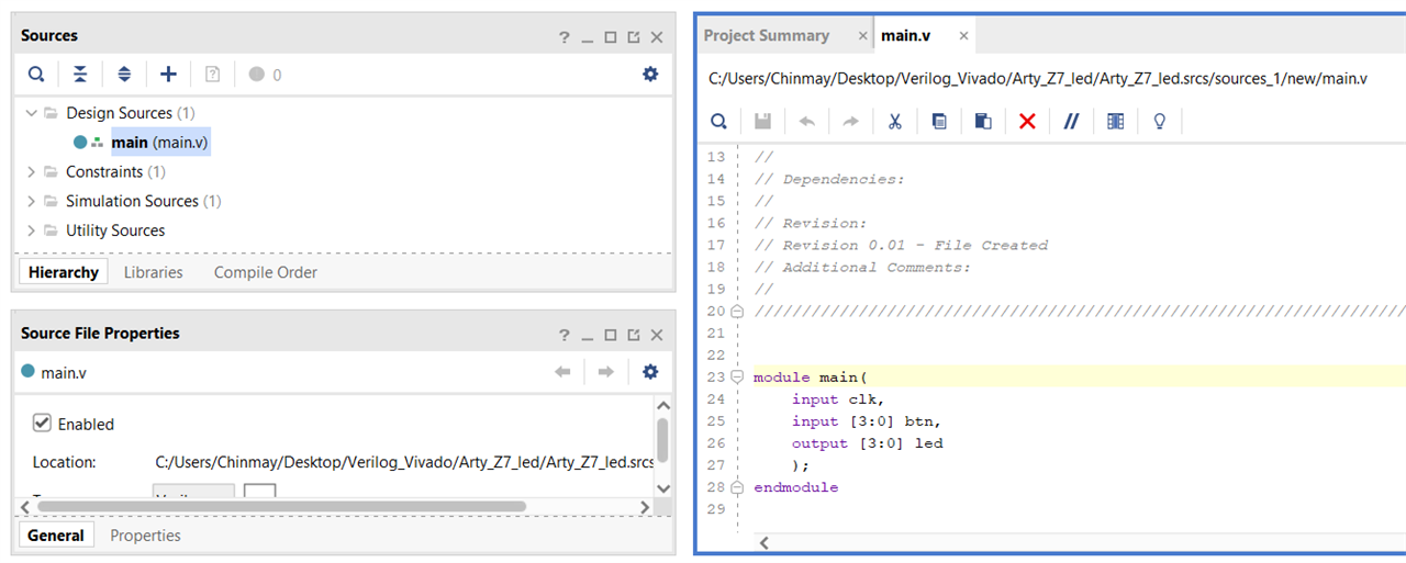
- Double clicking on the main.v file in the 'Sources' tab will open it for editing.
- Now, we will write the hdl code. So, the requirement is that when I press any one button out of {btn[3],btn[2],btn[1],btn[0]}, the corresponding led should turn on. And when the button is not pressed, it should turn off. The code is shown below:
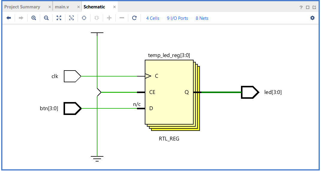
module main( input clk, input [3:0] btn, output [3:0] led ); reg [3:0] temp_led; always @(posedge clk) begin if(btn[0] == 1'b1) begin temp_led[0] = 1'b1; end else begin temp_led[0] = 1'b0; end if(btn[1] == 1'b1) begin temp_led[1] = 1'b1; end else begin temp_led[1] = 1'b0; end if(btn[2] == 1'b1) begin temp_led[2] = 1'b1; end else begin temp_led[2] = 1'b0; end if(btn[3] == 1'b1) begin temp_led[3] = 1'b1; end else begin temp_led[3] = 1'b0; end end assign led[3:0] = temp_led[3:0]; endmodule - Now, after writing the HDL code, we will get its circuit schematic by clicking on "Schematic" under the "RTL Analysis" drop down menu in the left pane. If there are no errors in the code, the schematic will be build successfully otherwise it will show the errors. My schematic is given below.
- Next, we will connect the board to the computer and run this code.
- Connect the board to the computer using a Micro USB cable. Some LEDs should be blinking on the board because of the preloaded code in it.
- Next step is to generate the bitstream. Actually, we need to run synthesis and implementation first but if we directly generate bitstream, it will automatically run them and then start generating the bitstream. Click on "Generate Bitstream" in the left pane. The following window will open.
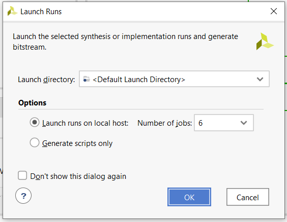
Select "Number of jobs" as your choice. The lower the number of jobs you choose, the more time it will take to generate the bitstream (but higher number of jobs will use more resources). Click on "OK".
The status of the process can be seen at top right corner of the window.
Some one line definitions:- Synthesis - It is a process to create logic from legal RTL.
- Implementation - It is the process of mapping a logical netlist to the physical array of a device
- Bitstream - It carries the information on which logical elements on the fabric should be configured and how in order to implement the target design.
- I got some failure while generating the bitstream. The error log reported some scary messages
as shown below.

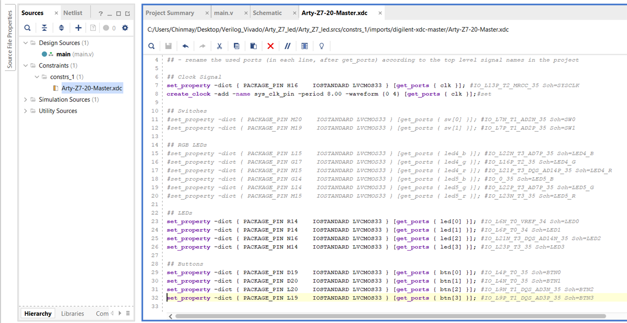
Since, the error message contained the term 'IOSTANDARD', I reviewed the constraint file because I remembered I had seen this term there. And it turned out that I had to uncomment the lines associated with the pins which I am using. It was written at the top of the file. So, I uncommented those lines in Vivado itself and tried to generate the bitstream again. This time it generated successfully.
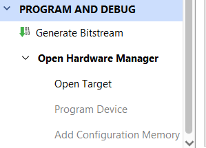
- Next, we want to connect to the board. For that, open the "Hardware Manager" from the left pane under "Program and Debug" drop down menu. Click on 'Open Target' and then 'Auto Connect'.
If it is able to successfully connect to the hardware, it will show the hardware details.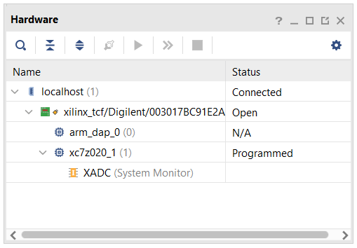
NOTE: Here I faced one issue. When I tried to do auto connect after plugging in my board to the computer, it couldn't recognize it and said 'no hardware target is open'. After doing a bit of search, I found the issue. I didn't have the latest drivers because of which it couldn't identify the board. But after updating the drivers, it worked fine. I followed the steps on this link. - After successfully connecting to the hardware, now we can load the program. For that, click on 'Program Device' under the Hardware Manager.
- Once the device is programmed successfully. We can test it by pressing various buttons. I have attached a short video below.
Summary
The Vivado Design Suite simplifies the process of building custom designs significantly. While I encountered a few issues along the way, the online community provided solutions for every problem I faced.
Reference

-

DAB
-
Cancel
-
Vote Up
0
Vote Down
-
-
Sign in to reply
-
More
-
Cancel
Comment-

DAB
-
Cancel
-
Vote Up
0
Vote Down
-
-
Sign in to reply
-
More
-
Cancel
Children