


|
EVA Guardian
Intelligent EV Battery Insight, Safety & Emergency Response System
|
EZ-EV CHALLENGE FINAL REPORT |
Author: Sumanth M N
Design Challenge: EZ-EV Design Challenge (element14 Community)
Project Name: EVA Guardian
GitHub Repository: github.com/ForgedCircuits/EVA-Guardian
Edge Impulse Studio Project: Edge Impulse Project #1076458
Project Video Walkthrough: YouTube: EVA Guardian
Executive Summary
As the world transitions rapidly toward clean electric mobility, electric two-wheelers and light EVs have become the backbone of urban transit. However, most modern light EV instrumentation remains fundamentally reactive—displaying simple battery percentage bars and generic warning lights only after a critical fault or breakdown has already occurred. Furthermore, in severe collision scenarios where the main high-voltage traction rail is severed or tripped by safety contactors, the vehicle loses all power, leaving riders stranded without emergency communication.
EVA Guardian is an intelligent, distributed edge-computing platform designed to make electric vehicles truly self-aware, proactive, and resilient. Built for the element14 EZ-EV Design Challenge,
EVA Guardian Features:
- Distributed Dual-Brain Architecture: Decouples battery analytics from incident monitoring across two dedicated Arduino UNO Q microcontrollers communicating over an isolated differential RS-485 bus.
- On-Device Edge AI Motion Classifier: Trained with Edge Impulse to distinguish normal riding dynamics (turns, acceleration, speed breakers, potholes) from actual crashes and tip-overs with sub-5ms latency and zero cloud dependence.
- Hybrid State of Charge (SoC) Engine: Combines real-time Coulomb counting with automatic 60-second Open-Circuit Voltage (OCV) relaxation recalibration, eliminating voltage sag distortion and sensor drift.
- Automated 4-Step Hardware Fault Diagnostics: An intelligent protocol that autonomously isolates whether a communication blackout is caused by the master transceiver, slave transceiver, or a severed harness cable.
- Predictive Connector Degradation & Auto-Failover: Real-time dual-point voltage sensing detects contact resistance buildup (ΔV > 1000mV) before thermal damage occurs, coupled with a seamless redundant backup battery path governed by the core rule: "If transportation stops, communication must not."

Figure 1 — EVA Guardian Complete Hardware Setup: Battery Management Node, Incident Detection Node, RS-485 Differential Bus, and Onboard Visual Displays.
The Core Problem: Beyond Static Battery Bars
Most modern electric two-wheelers display two main numbers: Battery Percentage (%) and Estimated Range (km).
Under real riding conditions, however:
When accelerating or climbing hills, cell internal resistance causes terminal voltage to drop significantly. Simple voltage-based meters report a false battery drop, confusing riders.
Over months of road vibrations and environmental exposure, crimps and high-current connectors oxidize. Contact resistance increases, leading to I²R localized power dissipation, terminal melting, and fire risks that standard BMS boards never flag.
Simple acceleration threshold triggers produce massive false-alarm rates over bumpy terrain and potholes.
When a crash occurs and the main battery breaker trips, vehicle telematics die instantly, leaving injured riders unable to broadcast emergency location and crash telemetry.
EVA Guardian was engineered from the ground up to solve each of these failure modes.
System Architecture & Design Philosophy
Rather than routing all sensors to a single centralized microcontroller—creating a single point of failure—EVA Guardian decouples vehicle intelligence into two modular nodes:

Figure 2: EVA Guardian High-Level Technical Architecture

Figure 3 — Detailed Technical Architecture: Signal conditioning front-ends, dual Arduino UNO Q SBCs, RS-485 bus, and redundant battery failover routing
The Three Architectural Pillars:
- Decoupled Responsibilities: Battery chemistry tracking and vehicle motion dynamics operate at fundamentally different timescales (10 Hz vs. 42 Hz) and are managed by independent processors.
- Differential Industrial Bus (RS-485): High-current motor controllers generate severe electromagnetic interference (EMI). Differential signaling over twisted pair via Analog Devices ADM3068E transceivers ensures zero packet loss in harsh electrical environments.
- Isolated Redundant Power Architecture: The Safety Node contains its own power management circuit and backup 2S battery pack, completely independent of the main traction bus.
Hardware Engineering & Analog Signal Conditioning
Precision analytics require clean, calibrated sensor signals. The analog front-end (AFE) of the Battery Node was designed to maximize signal integrity on the Arduino UNO Q's 14-bit ADC (0−16383 counts).
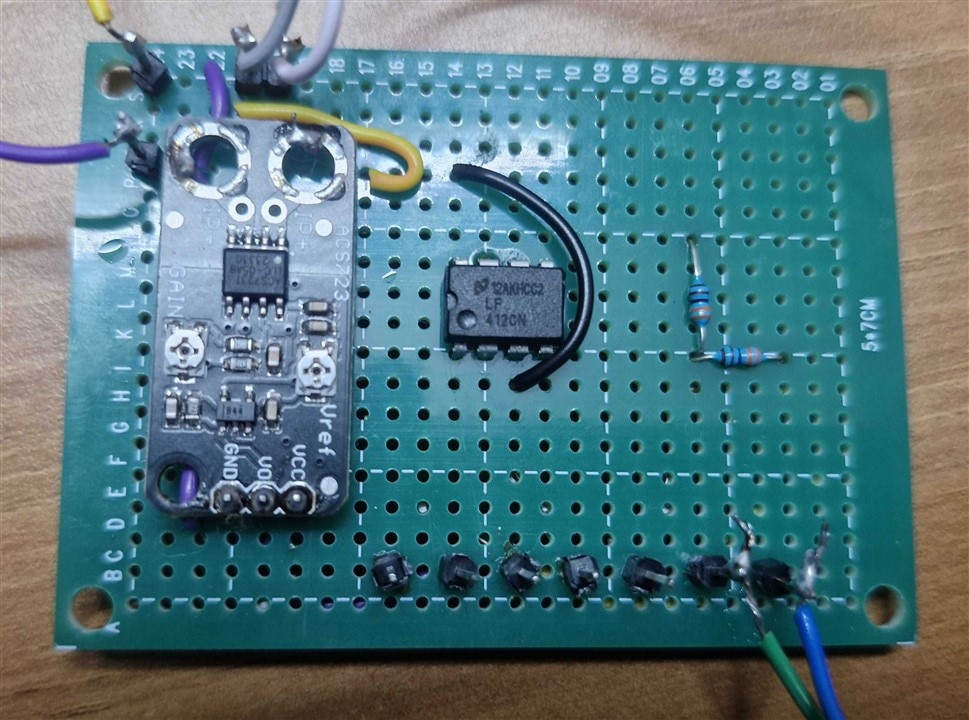
Figure 4: Precision Measurement Circuitry on Veroboard: LF412 buffer stage, ACS723 Hall-effect sensor, NTC bridge, and HX-2S-A2 protection module.
1. High-Impedance Pack Voltage Buffer (LF412)
Directly connecting a resistive divider to an ADC causes impedance loading errors. A precision divider (R1 = 6.8 kΩ, R2 = 3.0 kΩ) scales the 8.4V peak voltage down to a safe 2.57V. An LF412 dual JFET op-amp configured as a unity-gain voltage follower (10¹²Ω input impedance) isolates the divider, preventing ADC sampling charge-injection from skewing the measurement:
2. Isolated Bidirectional Current Measurement (ACS723)
An Allegro ACS723 Hall-effect linear current sensor is placed in series with the battery load:
- Galvanic isolation eliminates ground loop noise.
- Calibrated zero-current quiescent voltage: Vref ≈ 1.70 V.
- Sensitivity: S ≈ 1.336 V/A.
(Negative current indicates discharge through load; positive indicates charging).
3. Thermal Acquisition via Steinhart-Hart Equation
An NTC thermistor (10 kΩ nominal @ 25°C) is thermally bonded to the cells. The firmware converts resistance RNTC to temperature using the Steinhart-Hart β-parameter model:
Edge AI Motion Classification & Incident Detection
To eliminate false crash alarms caused by speed bumps and potholes, the Incident Detection Node utilizes on-device Edge Machine Learning.

Figure 5 — Edge Impulse Studio: 39-feature Power Spectral Density (PSD) extraction, 5-class motion dataset distribution, and validation confusion matrix.
Using the GY-91 (MPU6500 6-axis IMU) sampled at 42 Hz, approximately 11 minutes of real-world motion data was recorded across 5 distinct operational classes:
- Accident: High-g impact followed by rapid roll/tip-over and sustained tilt.
- Idle: Stationary with ambient engine/road rumble.
- Front and Back: Longitudinal acceleration and regenerative braking.
- Right and Left: Slalom cornering and banking angles.
- Up and Down: Transient vertical shocks from speed breakers and potholes.
Before feeding the neural network, the raw IMU stream passes through an Exponential Moving Average (EMA) filter (α = 0.25). An Edge Impulse Spectral Analysis block extracts 39 frequency-domain features, capturing the unique harmonic fingerprints of impacts versus bumps.
The classifier runs fully on-device on the Arduino UNO Q without cloud connectivity:
- Input Layer: 39 extracted PSD spectral features
- Dense Layer 1: 20 neurons (ReLU)
- Dense Layer 2: 10 neurons (ReLU)
- Dense Layer 3: 5 neurons (ReLU)
- Output Layer: 5 neurons with Softmax probability distribution
- Training Parameters: 50 epochs, learning rate = 0.0005 Adam optimizer.
Figure 6 — Interactive Displays: Electronic spirit-level water animation on Arduino UNO Q LED Matrix.
Battery Intelligence: The Hybrid SoC Algorithm
+─────────────────────────────────────────────────────────────────────────────+
| HYBRID SoC ALGORITHM LOGIC |
+─────────────────────────────────────────────────────────────────────────────+
| |
| 1. BOOT-UP: |
| • Read stabilized OCV from 14-bit ADC. |
| • Snap Coulomb counter (accumulatedAh) to OCV Lookup Table (LUT). |
| |
| 2. RUN-TIME DYNAMICS (Discharge / Charge): |
| • Coulomb Counting: ΔQ = I * Δt |
| • Charging Multiplier: 98% Coulombic efficiency |
| • Immunity to instantaneous voltage sags under motor PWM load |
| |
| 3. AUTOMATIC OCV RECALIBRATION: |
| • Rest Detection: Current |I| < 50 mA |
| • Relaxation Window: 60 continuous seconds at rest |
| • Action: Sync Coulomb Counter back to True Chemical OCV curve |
| • Zero Drift Accumulation over time! |
+─────────────────────────────────────────────────────────────────────────────+
Mathematical Formulation: During operation, charge is tracked second-by-second:
- η = 1.00 during discharge (I < 0)
- η = 0.98 during charge (I > 0) to account for Coulombic losses.
- When the vehicle rests (|I| < 50 mA) for trest ≥ 60 s, the chemistry stabilizes, and the algorithm recalibrates the Coulomb counter against the non-linear Open-Circuit Voltage Lookup Table (OCV-LUT), eliminating sensor drift.
Deterministic RS-485 Protocol & 4-Step Fault Diagnostics
Custom Binary Packet Framing: Inter-node communication follows a deterministic master-slave polling cycle every 2.0 seconds:
+-----------+-----------+---------------+---------+--------------------+---------+-----------+
| SOF [0] | SOF [1] | Payload Len | Command | Payload | CRC | EOF |
| 0x55 | 0xAA | (1 Byte) | (1 Byte)| (N Bytes) | (1 Byte)| 0xAA |
+-----------+-----------+---------------+---------+--------------------+---------+-----------+
Autonomous 4-Step Fault Diagnostic State Machine: When communication ceases for > 30 seconds, EVA Guardian executes an internal diagnostic sequence to isolate the exact failure point:

Figure — Autonomous 4-Step Fault Diagnostic Routine Flowchart
→ IDS RS-485 Transceiver Hardware Fault.
→ BMS RS-485 Transceiver Hardware Fault.
→ Communication Cable Fault / Disconnected Wire.
Power Harness Degradation & Automatic Power Failover
Contact Resistance Monitoring: Connectors develop contact resistance (Rcontact) through oxidation and vibration. EVA Guardian performs continuous dual-point differential voltage sensing:
ΔV = V_BMS - V_IDS = 0.65 V → [ WebUI Warning: "Connector Degradation Detected!" ]
Physical Scale Demonstrator & WebUI Dashboard
To validate EVA Guardian in a realistic physical environment, a scale-model electric vehicle chassis was constructed:
- Spatial Separation: Rear compartment houses the primary 2S battery pack, HX-2S-A2 BMS, and Node 1 electronics.
- Cockpit Integration: Front compartment houses the Incident Detection Node, backup battery pack, power transfer relay, and onboard matrix display.
- Harness Routing: Distinct cable channels for high-current power lines and differential RS-485 twisted pairs.
- Live WebUI Dashboard: Real-time web browser interface providing comprehensive telemetry: live pack voltage, current, temperature, SoC%, SoH%, 3D orientation visualizer, connector health status, and diagnostic error codes.
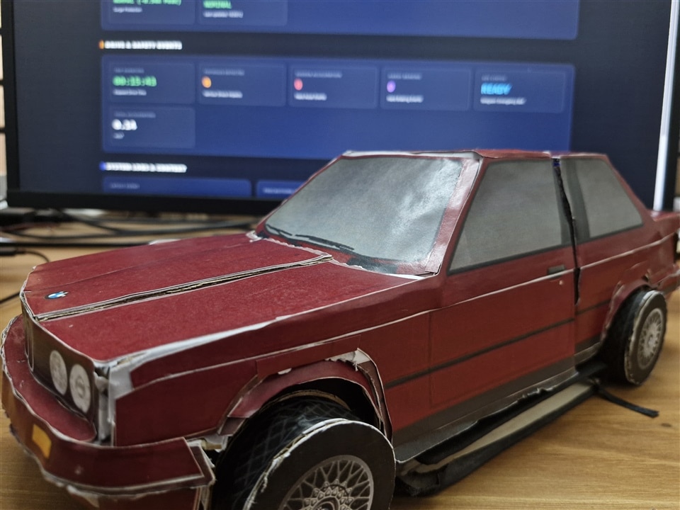
Chassis & Harness Routing: Assembled scale EV demonstrator with the live system telemetry dashboard |
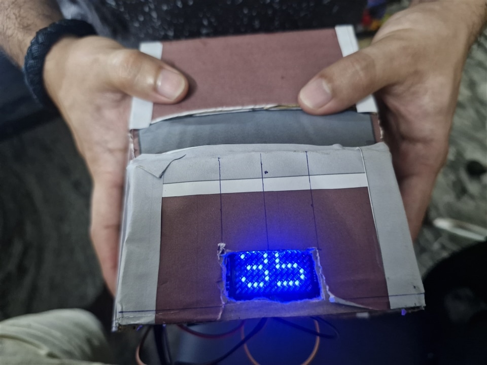
Rear Powertrain & BMS Node: Integrated rear matrix display actively rendering telemetry data on the scale model. |

Hardware Integration: Spatial separation of high-power traction rails and differential RS-485 communication bus. |
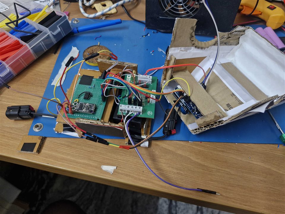
BMS Module: 2S Li-ion pack, HX-2S protection board, and analog signal conditioning module. |

Battery Telemetry View: Real-time pack voltage, SOC%, SOH%, current, temperature, and connector health. |

Incident Telemetry View: Continuous monitoring of abnormal motions, suggesting precautionary measures |
Experimental Validation & Fault Injection Testing
The entire system was subjected to rigorous stress tests and deliberate fault injection:
Complete Video Demonstration Suite
The complete hardware validation and fault-injection scenarios have been recorded and documented in detail:
Bill of Materials (BOM)
| # | Part Number | Manufacturer | Description | Qty | Reference / Link |
|---|---|---|---|---|---|
| 1 | ABX00162 | Arduino | ARDUINO UNO Q 2GB RAM 16GB EMMC | 2 | element14 • UNO Q SBC |
| 2 | EVAL-ADM3068EEBZ | Analog Devices | EVAL BOARD FOR ADM3068E RS-485 | 2 | element14 • ADM3068E Eval |
| 3 | MX150 Receptacle | Molex | Cable Assembly, MX150 Receptacle to Free End, 2 Ways, 600 mm | 3 | element14 • MX150 Cable |
| 4 | ACS723 Module | Smart Elex | SmartElex Current Sensor Breakout - ACS723 (Low Current ±5A) | 1 | Robu.in • ACS723 Breakout |
| 5 | L298N Motor Driver | Smart Elex | SmartElex 2x2A DC Dual Motor Controller V2 (L298N) | 1 | Robu.in • L298N Driver |
| 6 | 18650 Battery Charger | Generic | 2S 8.4V 2A 18650 Lithium Battery Charger Module Type C | 1 | Robu.in • 2S Type-C Charger |
| 7 | 18650 Li-ion Cells | Generic | 18650 Capacity Li-ion Battery Cells | 4 | — |
| 8 | Battery Holder | Generic | 18650 x 2 Battery Holder with Cover and On/Off Switch | 2 | — |
| 9 | HX-2S-A2 BMS | Generic | HX-2S-A2 Circular 2S 8.4V BMS 18650 Protection Board | 2 | Robu.in • HX-2S-A2 Module |
| 10 | LF412 | Texas Instruments | LF412 Dual JFET Input Operational Amplifier IC DIP-8 | 1 | Robu.in • LF412 Op-Amp |
| 11 | 5V SPDT Relay | Generic | 5V SPDT Relay IC | 1 | — |
| 12 | 5V Relay Module | Generic | 5V 4-Channel Relay Module | 2 | Robu.in • 4-Ch Relay |
| 13 | GY-91 IMU | Generic | GY-91 MPU6500 + BMP280 7DOF IMU Sensor Module | 1 | Robu.in • GY-91 Sensor |
| 14 | NTC Thermistor | Generic | 10k Ohm NTC Thermistor (Steinhart-Hart Calibrated) | 1 | Robu.in • 10k NTC |
Lessons Learned, Challenges & Future Roadmap
Technical Challenges Overcome:
Implementing unity-gain LF412 op-amp buffers and firmware-level Exponential Moving Average (EMA) filtering reduced measurement noise by over 90%.
Relying on single-frame IMU spikes caused potholes to mimic accidents. Transforming data into the frequency domain via Power Spectral Density (PSD) in Edge Impulse and requiring a 3-consecutive-window confirmation completely eliminated false triggers.
Concurrently updating sensor telemetry, running neural network inference, and refreshing the LED matrix initially caused display artifacts. Implementing Zephyr RTOS mutexes resolved all resource contention.
Conclusion & Acknowledgments
EVA Guardian demonstrates that smart, predictive, and crash-resilient safety features do not require expensive automotive supercomputers. By combining low-cost embedded hardware (Arduino UNO Q), thoughtful analog circuit design, robust differential communication (RS-485), and lightweight on-device Machine Learning (Edge Impulse), we can build electric vehicles that are genuinely self-aware.
From detecting microscopic contact resistance degradation to autonomously isolating severed cables and preserving emergency communication through a crash, EVA Guardian sets a new benchmark for light electric vehicle safety.
Note: The formatting and styling is done using AI.
Actually I dont know anything about HTML,CSS and all, just found a way like in e14 blog we can edit the html source of the blog post so tried it out
How is it looking !!!!
Project Links & Resources
GitHub Repository: https://github.com/ForgedCircuits/EVA-Guardian.git
Edge Impulse Studio: https://studio.edgeimpulse.com/public/1076458/live
Project Video Playlist: https://youtube.com/playlist?list=PLZW8QVft8LFI&si=9F5fQt6vnm0wEl0R
Top Comments