


Project GEPARD V5.0: Final Summary, Scope Creep, and Engineering Retrospective
After weeks of aggressive CAD modeling, 3D printing failures, strict power routing, bare-metal coding, and an absolute gauntlet of hardware troubleshooting, Project GEPARD has officially reached the end of its Build 1 phase for the Element14 EZ-EV Smart Transportation Challenge.
GEPARD (Ground EV Perception and Autonomous Routing Dock) was never intended to be a simple remote-controlled toy. My overarching goal was to engineer a scaled-down, autonomous UGV (Unmanned Ground Vehicle) prototype that could serve as a modular testbed for operational analytics, energy efficiency testing, and security simulations. I set out to replicate the end-to-end lifecycle of an industrial electric vehicle within a 1-foot-tall footprint.
What follows is the complete story of this build: the initial dream, the crushing reality of scope creep, the countless mechanical pivots, the sponsor hardware that made it possible, and the hardware graveyard I left behind.
1. The Initial Vision and The Trap of Scope Creep
When I first drafted the blueprint for GEPARD, my ambition vastly outpaced my experience. I envisioned a Tri-Node Intelligence Pipeline:
-
Node 1 (The Edge): The rover, executing autonomous obstacle avoidance and visual SLAM.
-
Node 2 (The Router): A local PC running YOLOv8 for zero-latency computer vision and an Ollama local LLM for auditory logic triage.
-
Node 3 (The Cloud): Gemini API handling multimodal reasoning to control smart home devices via voice.
I wanted it to autonomously dock using ArUco markers, act as a motion-detecting security sentinel, and log its own power telemetry dynamically. I tried to wire, code, and test all of these systems simultaneously.
This was my first and most fatal mistake: Massive Scope Creep. I spent dozens of hours hopelessly debugging a tangled, multi-node system where power bugs, logic-level mismatches, and software errors all overlapped. I had no idea if a sensor failure was due to a bad ground, a typo in my Python script, or a blown I2C bus. I learned the hard way that you must define a strict Minimum Viable Product (MVP)—in my case, just making the motors spin—and test one single circuit at a time before integrating it into a master chassis.
2. The Isolation Trap: A Lesson Learned
If there is one overarching takeaway from this entire experience, it is this: compared to the veteran engineers on the Element14 forum, I am at the absolute bottom of the robotics learning curve. And yet, I tried to build this entire complex machine in complete isolation.
When my I2C bus failed, when my tracks bound up, and when my compiler threw phantom errors, I put my head down and tried to brute-force the solution for days. I should have asked this community for help. You all have decades of experience, and my stubbornness cost me the most valuable resource in any design challenge: time. To any beginners reading this: pre-plan your build, and the moment you hit a wall, leverage the community.
3. Mechanical Forensics: Iterations, Tracks, and Wheels
The physical design of GEPARD went through five massive iterations, largely driven by the harsh realities of 3D printing and mechanical stress.
Monolithic vs. Split Hull: I initially tried to print the hull as a single monolithic piece. It continually failed on my Ender 3 V2 and wasted massive amounts of filament. I pivoted to a 4-part split hull (Bottom Front/Back, Top Front/Back), utilizing brass heat-set inserts to bolt the framework together into a rigid structure.
RWD to FWD: I started with a Rear-Wheel Drive layout, but the dense mass of the Ziqqucu 3S2P battery box mounted in the rear caused severe tipping hazards during sudden acceleration. I redesigned the chassis to Front-Wheel Drive (FWD) so the heavy JGA25-370 propulsion motors would counterbalance the battery, neutralizing the tipping risk.
The Track vs. Wheel Dilemma: This was my biggest mechanical nightmare. I desperately wanted the "ripsaw" aesthetic and traction of 35mm TPU tank tracks. However, the friction and torque required to turn tracks tore my drivetrain apart:
-
Rear Axle Spacer Degradation: I designed cylindrical spacers for the rear idlers. The track friction ground these spacers to dust in hours, creating a severe slant that threw off the track tension entirely. I had to pivot to flat, circular pads to distribute the friction.
-
Front Sprocket Inward Camber: The tension of the tracks pulling on the front drive wheels migrated upwards, concentrating torque toward the roof of the 3D-printed axle housing. This progressively warped the alignment, causing the front wheels to camber inward and bind the motors. The constant battle of keeping the tracks tensioned without destroying the plastic chassis made me seriously consider pivoting entirely to a standard 4-wheel rover. FDM printing tolerances for tracked drivetrains require far more structural reinforcement at the motor mounts than I originally calculated.
4. Sponsor Hardware & The Split-Brain Architecture
This build would absolutely not have been possible without the hardware provided by the challenge sponsors.
The Arduino UNO Q (STM32 + QRB2210)
The UNO Q acted as the undisputed hero component of this build. By utilizing the Arduino_RouterBridge protocol, I leveraged its unique dual-brain architecture.
I assigned the STM32U585 microcontroller to act as the "spinal cord." It handles all the fast, deterministic hardware reflexes: reading the HC-SR04 ultrasonic sensors, managing hardware-level emergency stops, and outputting PWM signals to the TB6612 motor controller.
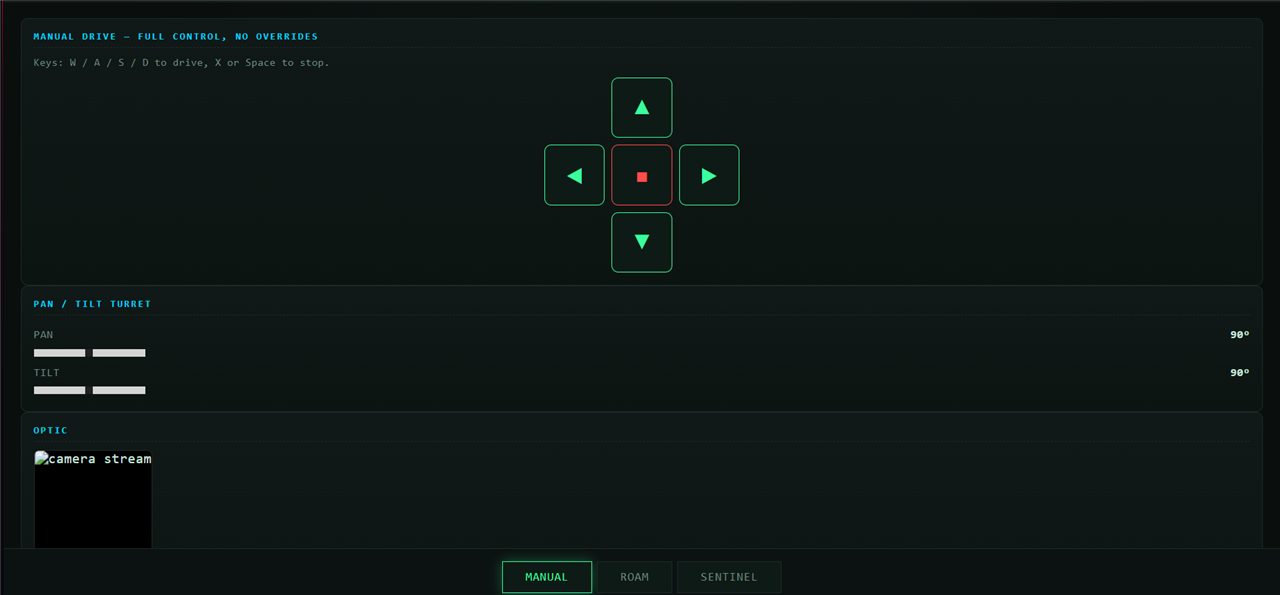
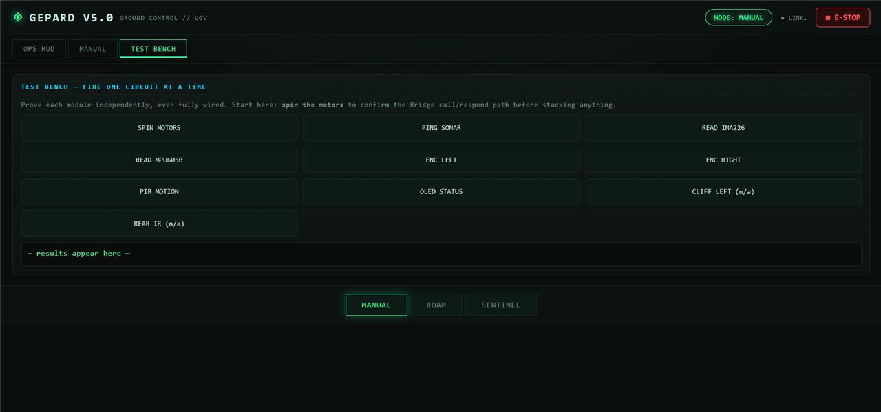
Meanwhile, the Qualcomm QRB2210 Linux SBC acts as the high-level brain. It runs a Python script that continuously listens for UDP drive commands from my laptop, passes those commands down to the STM32 via the Bridge, and broadcasts the returning sensor registry back to my custom Python GUI dashboard.
The ADI ADM3068E RS485 Transceivers
These transceiver boards are the cornerstone of the GEPARD autonomous docking architecture. You cannot safely leave live 12V power resting on exposed metal pogo pins—it is a massive fire hazard. To solve this, I designed a cold-launch relay system.
The ADM3068E boards facilitate a highly EMI-resistant cryptographic handshake between the rover and the dock. When the rover makes physical contact with the dock's 4-pin magnetic data array, it parasitically boots the dock's logic board. The RS485 handshake ensures that the dock verifies the identity of the rover. Only after verification does the dock trigger a 5V relay to close, safely sending the 12.85V charging power through the pins and into the rover.
5. The Hardware Graveyard and Software Black Boxes
My attempt to build a flawless telemetry system collided violently with the real world.
The Optical Encoder Failure: My odometry tracking relied on TCRT5000 IR sensors reading the negative space in the custom drive sprockets. This failed completely. The black PETG filament absorbed the IR light rather than reflecting it, and the 5 concave holes were spaced too closely together for the sensor to distinguish the gaps at speed. The encoder data returned mostly zeroes. Optics require high-contrast materials and perfect mathematical spacing.
The INA226 Telemetry Enigma: I intended to track power consumption using an INA226 I2C sensor. The sensor simply refused to communicate. I tested the raw silicon using a multimeter in Diode Mode and read a healthy 500mV drop across the SDA and SCL pins, proving the internal logic chip was alive. Yet, the I2C bus remained dead. The massive physical shunt resistor still worked flawlessly, passing the full 11.3V battery power to the motors as a "dumb bridge," but the data lines remained totally silent.
The Dead MPU6050 & Servo: Tracked vehicles suffer from severe heading drift, so I integrated an MPU6050 IMU. Without warning, the chip simply died. Shortly after, the MG90S micro-servo controlling my ultrasonic turret burned out on the bench, forcing a complete turret teardown.
The App Lab & Bridge Black Box: Working with the Arduino App Lab introduced constant environment quirks where it would state "Library Added," but the compiler would throw fatal missing-module errors. Furthermore, while the Arduino_RouterBridge worked syntactically to pass my UDP strings, the actual mechanics of how the Qualcomm chip parses data to the STM32 is a complete black box to me. Debugging bare-metal RTOS communication protocols without deep diagnostic tooling was terrifying.
6. The Final Real-Life Hurdle
Right before the final submission deadline, real life intervened. My house was hit by a sudden, severe mice and rat infestation. Securing my living space, cleaning, and dealing with the extermination wiped out my crucial remaining bench time.
This is exactly why the final electrical wiring for the dock's power supply could not be completed, and why my video demonstrations rely on an unpowered, mechanical Proof of Concept for the docking approach, and a focus on the structural integrity of the chassis and wireless UDP control.
7. Open Source Architecture & Reproducibility
A well-documented 80% complete project is infinitely more valuable to the engineering community than a poorly documented 100% complete project. Every file required to reproduce Project GEPARD is available below.
-
Code Repository: Project-Gepard Code Includes the bare-metal C++
sketch.ino, the Linux-sidemain.pyUDP router, the PC-side Python GUI, and telemetry dashboard scripts. -
3D CAD Files:Gepard CAD File Includes the 4-part split hull, turret, negative-space sprockets, and docking station.
System Wiring Diagram

8. Final Thoughts
I want to extend a massive thank you to Element14, Arduino, and Qualcomm for sponsoring this challenge and pushing me far out of my comfort zone. I took on a project whose scope was vastly too large for my current skill level, but the lessons I learned about mechanical tolerances, solderless power routing, and dual-brain logic routing are invaluable.
I am walking away from this challenge as a significantly better engineer. Thank you to everyone on the forum who followed this build, offered advice, and read through my debugging logs.
As I am away from my home due to extermenation going on please enjoy the videos I have used in previous posts I only brought my necessities to my friends house.
Images of HUD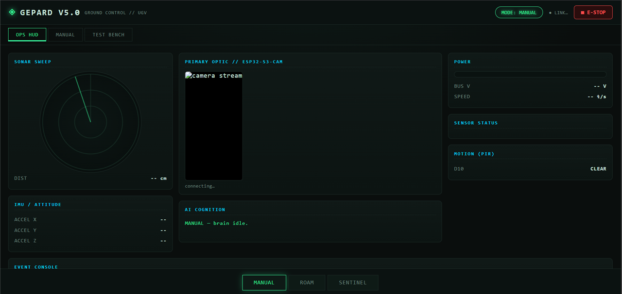
— John Htun