


Recap
I am building a robotic system that identifies the charging port on an EV and automatically moves a charger arm to plug the charger in.
Past Forum Posts:
The problem in technical terms
For a given car model, the charging port is always at the same height. But the driver can park closer or farther away, or stop too far forward or back. The robot needs to figure out exactly where the port is each time. Here is an Half AI , Half Photopea Edited picture to make things easier.

Robot needs to know its own position. That can come from joint encoders, stepper step counts from a home position, Lidar, or vision. I chose vision because a single camera system can identify the car model, locate the charging port, and tell the robot where it is relative to the target - all at once. Aruco markers make the position-from-vision problem much more tractable.
What Are Aruco Markers
Aruco markers are square fiducial markers - basically printed QR-code-like patterns with a thick black border and a unique binary pattern inside. OpenCV has had native Aruco support for years and it works excellently. This is good especially since when i was using this during my Bachelors in engineering, I had to compile OpenCV from scratch t have Aruco. Here is a good video demo on how they work: https://www.youtube.com/watch?v=MlOy9qt_K4Y

I generated my markers at chev.me/arucogen using the Aruco MIP 36h12 dictionary. I chose this dictionary because the calibration board I got from Internet (https://github.com/PlusToolkit/PlusLibData/blob/master/ConfigFiles/OpticalMarkerTracker/aruco_calibration_board_a4.pdf) also uses this dictionary. Any dictionary works - the important thing is to use the same one for both calibration and detection.
Installing on Debian / Raspberry Pi
OpenCV comes with Aruco support built in. On Debian or Raspberry Pi OS (I am running Mainsail OS for Klipper as i am repurposing an existing RPi):
pip install opencv-python-headless
sudo apt install -y python3-picamera2
Camera Calibration
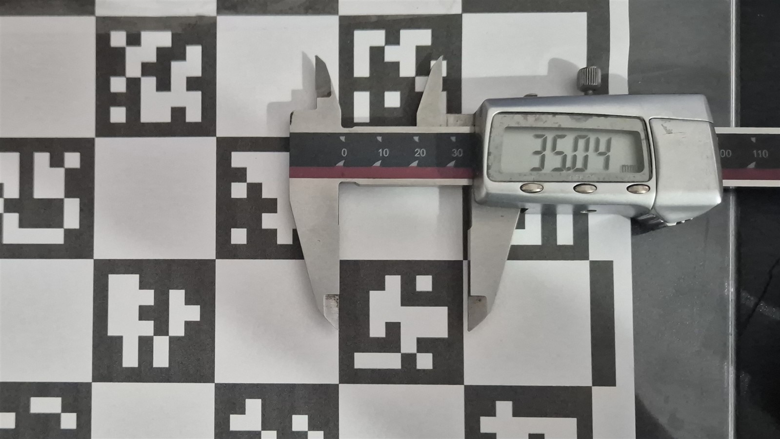
Before you can get an accurate 3D pose from a marker, you need to calibrate the camera. Every lens introduces distortion. I am not getting into details because I forgot the theory. But what I do know is that to calibrate, you need a known target. I used an 8×5 Aruco MIP 36h12 grid board with 35 mm markers which i found online.
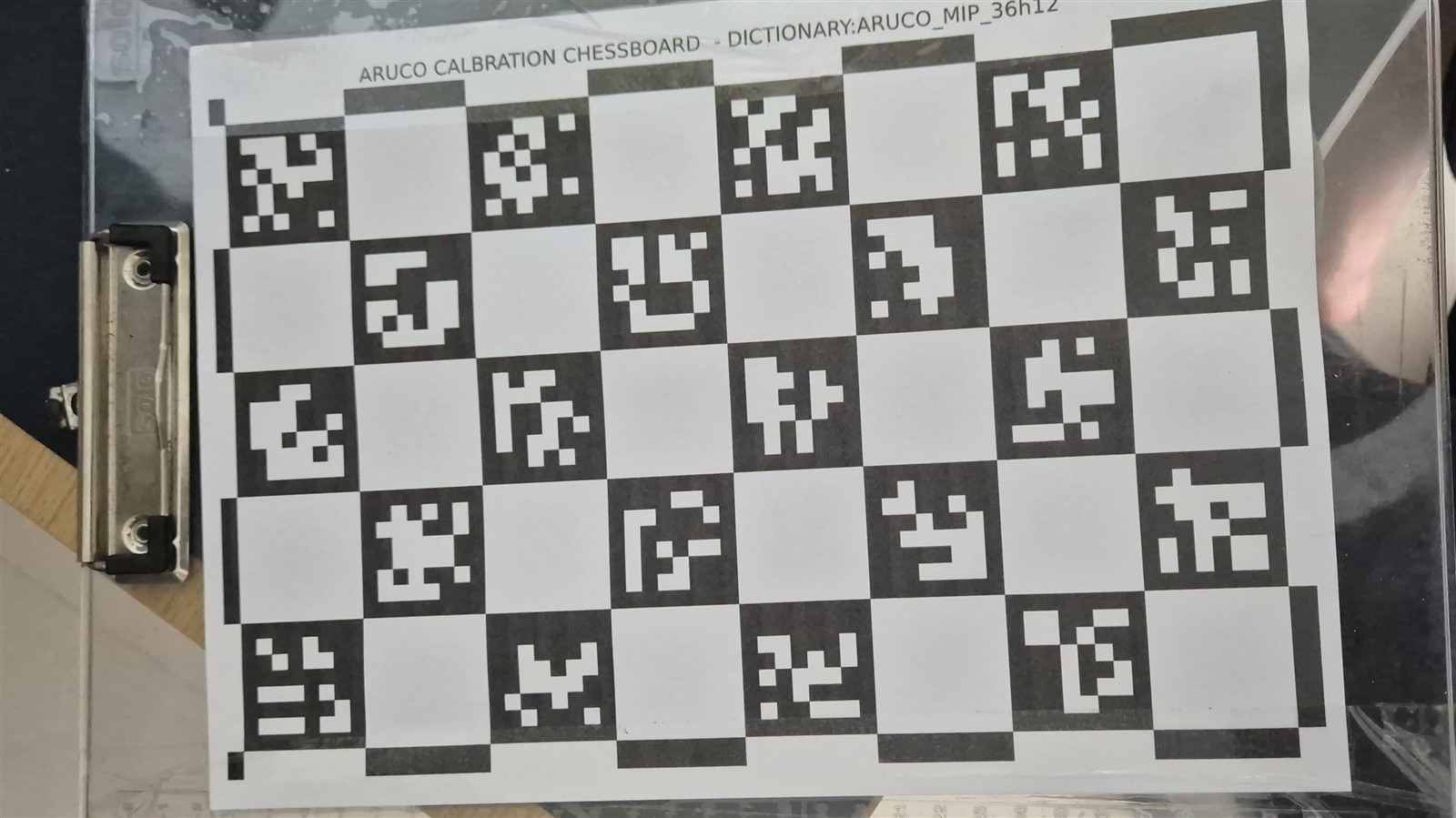
You show the board to the camera from different angles and distances - at least 5 frames, more is better. OpenCV's calibrateCamera then solves for the camera matrix and distortion coefficients by matching the known 3D corner positions on the board to where they appear in each image.
Calibration quality is measured by RMS reprojection error - how many pixels off the estimated corner positions are from the detected ones. Below 1.0 is good. Above that and your pose estimates will drift. Calibration only needs to be done once per camera and is saved to disk. After that it loads automatically on server start.
Step 1 - Just Get Markers Detected
The first script did nothing clever. Grab a frame, run the Aruco detector, print which IDs were found:
import cv2
from picamera2 import Picamera2

picam2 = Picamera2()
picam2.configure(picam2.create_preview_configuration(main={"size": (640, 480)}))
picam2.start()

aruco_dict = cv2.aruco.getPredefinedDictionary(cv2.aruco.DICT_ARUCO_MIP_36h12)
params = cv2.aruco.DetectorParameters()
detector = cv2.aruco.ArucoDetector(aruco_dict, params)

frame = picam2.capture_array()
frame = cv2.cvtColor(frame, cv2.COLOR_RGBA2BGR)

corners, ids, _ = detector.detectMarkers(frame)
if ids is not None:
    print("Detected:", ids.flatten().tolist())
else:
    print("Nothing detected")
Hold up a marker, it prints the ID. Simple sanity check before building anything more complex.
For the actual server I tuned the detector parameters to be more robust under varying lighting conditions - wider adaptive threshold window, sub-pixel corner refinement:
_params = cv2.aruco.DetectorParameters()
_params.adaptiveThreshWinSizeMin = 3
_params.adaptiveThreshWinSizeMax = 53
_params.adaptiveThreshWinSizeStep = 4
_params.adaptiveThreshConstant = 7
_params.minMarkerPerimeterRate = 0.02
_params.maxMarkerPerimeterRate = 4.0
_params.polygonalApproxAccuracyRate = 0.05
_params.cornerRefinementMethod = cv2.aruco.CORNER_REFINE_SUBPIX
detector = cv2.aruco.ArucoDetector(aruco_dict, _params)
Sub-pixel corner refinement (CORNER_REFINE_SUBPIX) is worth turning on - it measurably improves pose accuracy because solvePnP is very sensitive to where exactly the corners land.
Step 2 - Streaming Frames Over the Network
Running code on the Pi and squinting at SSH output is not great for development. I wanted to see the camera feed on my laptop. So I built a TCP server on the Pi that grabs frames, detects markers, draws them on the frame, and sends the JPEG plus a JSON payload with the marker data.
The protocol is simple: a 4-byte length prefix, followed by a JSON metadata blob, followed by the JPEG bytes. The same framing is used in both directions.
def send_msg(conn, payload: dict, image: bytes = None):
    """Length-prefixed: [4B json_len][json][image_bytes]"""
    if image:
        payload["image_len"] = len(image)
    raw = json.dumps(payload).encode()
    header = struct.pack(">I", len(raw))
    conn.sendall(header + raw)
    if image:
        conn.sendall(image)

def recv_msg(sock):
    hdr = _recvall(sock, 4)
    if not hdr:
        return None, None
    (length,) = struct.unpack(">I", hdr)
    body = _recvall(sock, length)
    meta = json.loads(body.decode())
    image = None
    if meta.get("image_len", 0) > 0:
        image = _recvall(sock, meta["image_len"])
    return meta, image
The streaming runs at full camera speed for data but sends JPEG images at only 4 FPS. There is no point sending 30 JPEGs per second over a home WiFi link when the pose data is what matters. Images are just for visual feedback.
On the client side, view.py connects, starts the stream, and renders the incoming frames in an OpenCV window while printing the pose table in the terminal:
send_cmd(sock, {"cmd": "stream_start"})
while True:
    meta, image = recv_msg(sock)
    if image:
        buf = np.frombuffer(image, dtype=np.uint8)
        frame = cv2.imdecode(buf, cv2.IMREAD_COLOR)
        cv2.imshow("DockBot", frame)
        if cv2.waitKey(1) & 0xFF == ord("q"):
            break
    print_table(meta.get("markers", []))
Step 3 - Camera Calibration Workflow
I added calibration commands to the server. The workflow from the client is:
- Print or display the 8×5 Aruco MIP 36h12 board
- Send
cal_addwhile holding the board in view at different angles - tilt it, rotate it, bring it closer and farther - Collect at least 15 frames with good variation
- Send
cal_compute
elif action == "cal_add":
    frame = grab_bgr()
    corners, ids, _ = detector.detectMarkers(frame)
    if ids is not None and len(ids) >= 4:
        obj_pts, img_pts = cal_board.matchImagePoints(corners, ids)
        if obj_pts is not None and len(obj_pts) >= 4:
            with cal_lock:
                cal_frames.append((obj_pts, img_pts))
                count = len(cal_frames)
            send_msg(conn, {"status": "ok", "message": f"frame {count} added"}, ...)

elif action == "cal_compute":
    rms, mtx, dist, _, _ = cv2.calibrateCamera(
        obj_pts, img_pts, (FRAME_W, FRAME_H), None, None)
    if rms < 1.0:
        _save_calibration(mtx, dist)
        msg = f"RMS {rms:.4f} - saved to disk"
    else:
        msg = f"RMS {rms:.4f} ! too high - tilt/rotate board more and try again"
On the server, cal_add calls cal_board.matchImagePoints() to get 3D-to-2D point correspondences for that frame. cal_compute accumulates all frames and calls cv2.calibrateCamera():
If the RMS is below 1.0 the calibration is saved to disk and loaded automatically on the next server start.
Once calibrated, refineDetectedMarkers also kicks in. It uses the board geometry to recover markers that were just below the detection threshold - useful when part of the board is in shadow.
One thing to be careful about: the calibration board markers are 35 mm, but the dock markers I printed are 80 mm (larger because the camera may be placed further away in deployment). These are separate constants in the code:
CAL_MARKER_LENGTH = 0.035   # metres - calibration board markers
MARKER_LENGTH     = 0.080   # metres - dock markers used for pose estimation
Mixing them up gives you pose distances that are off by the ratio of the two sizes. The calibration board size is only used during calibration to define 3D object points. The dock marker size is used later for pose estimation.
Step 4 - Pose Estimation
Once the camera is calibrated, getting the 3D position of each marker is straightforward. The detect() function handles detection, refinement, pose estimation, and drawing all in one pass:
MARKER_OBJ_PTS = np.array([
    [-_half,  _half, 0],
    [ _half,  _half, 0],
    [ _half, -_half, 0],
    [-_half, -_half, 0],
], dtype=np.float32)

def detect(frame):
    corners, ids, rejected = detector.detectMarkers(frame)
    if camera_matrix is not None:
        corners, ids, rejected, _ = cv2.aruco.refineDetectedMarkers(
            frame, cal_board, corners, ids, rejected,
            cameraMatrix=camera_matrix, distCoeffs=dist_coeffs
        )
    markers = []
    if ids is not None:
        cv2.aruco.drawDetectedMarkers(frame, corners, ids)
        for i, mid in enumerate(ids.flatten()):
            if int(mid) not in ALLOWED_IDS:
                continue
            entry = {"id": int(mid), "corners": corners[i][0].tolist()}
            if camera_matrix is not None:
                img_pts = corners[i][0].astype(np.float32)
                _, rvec, tvec = cv2.solvePnP(
                    MARKER_OBJ_PTS, img_pts, camera_matrix, dist_coeffs,
                    flags=cv2.SOLVEPNP_IPPE_SQUARE,
                )
                cv2.drawFrameAxes(frame, camera_matrix, dist_coeffs, rvec, tvec, _half)
                entry["tvec"] = tvec.flatten().tolist()
                entry["rvec"] = rvec.flatten().tolist()
            markers.append(entry)
    return markers
SOLVEPNP_IPPE_SQUARE is the right solver for square planar targets - it gives two solutions and picks the better one. The translation vector tvec is the X, Y, Z position of the marker centre relative to the camera in metres. Z is depth (straight ahead), X is left/right, Y is up/down.
drawFrameAxes draws the 3D coordinate axes on each detected marker in the live stream so you can immediately see the orientation of each marker - satisfying to watch when it works.
Detection is filtered to IDs 0 through 7. Any stray detections from other sources are silently dropped.
The client prints a live-updating pose table from the stream data:
If you notice closely, you'll see the estimation of pose are quite off by a large magnitude. That's when it hit me that the size of markers used to calibrate (35mm) is not the same as the one using to estimate pose (80mm) . So I changed the code to compensate for it at this point.
The XYZ Plot
To verify the pose estimate is stable, I wrote a separate script that connects to the server and live-plots the X, Y, Z components of marker ID 0 over time using matplotlib. The network receiver runs in a background thread and pushes data into a queue; the animation callback drains it:
def receiver(host, port, q: queue.Queue):
    sock = socket.socket(socket.AF_INET, socket.SOCK_STREAM)
    sock.connect((host, port))
    send_cmd(sock, {"cmd": "stream_start"})
    while True:
        meta, _ = recv_msg(sock)
        if meta is None:
            break
        for m in meta.get("markers", []):
            if m["id"] == MARKER_ID and "tvec" in m:
                q.put((time.monotonic(), m["tvec"]))

def update(_frame):
    while not q.empty():
        t, (x, y, z) = q.get_nowait()
        ts.append(t - t0); xs.append(x); ys.append(y); zs.append(z)
    # drop data older than 10 seconds
    cutoff = time.monotonic() - t0 - HISTORY_S
    while ts and ts[0] < cutoff:
        ts.popleft(); xs.popleft(); ys.popleft(); zs.popleft()
    ...

ani = animation.FuncAnimation(fig, update, interval=50, blit=True)
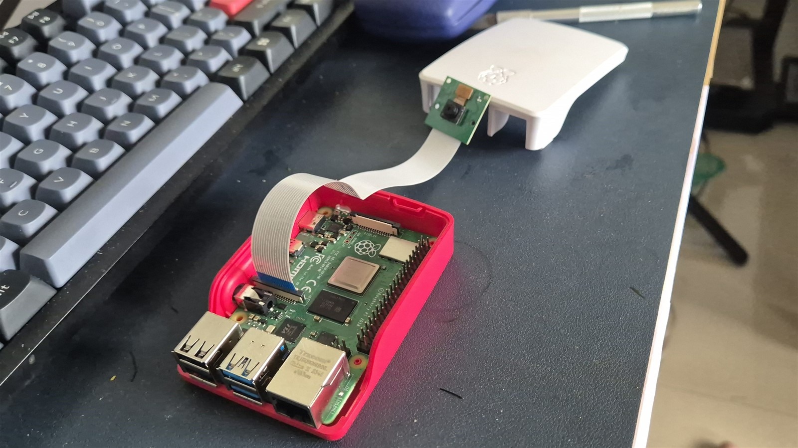
Holding a marker steady and watching the lines tells you immediately how stable the calibration is. A wobbly line means more calibration frames or better angle variation are needed. Obviously, it's not perfect, But I will improve it after integration, as I need to hold the camera steady first. For now, it's resting over the Rpi Case.
Code
The Full code for this can be found under post2 folder at https://gitlab.com/arvindsa/dockbot-e14-challenge
Final Notes
There was a time I had to compile OpenCV from source just to get Aruco support. Now a single pip install does it. Now that I can reliably locate markers in 3D space, the next step is the physical robot - the gantry hardware.


