


Building the Technical Architecture: From EV Battery Intelligence to Emergency Safety
In my previous post: Part EV Guardian - Part 1,
I introduced EVA Guardian and the motivation behind the project — an intelligent EV platform designed not just to monitor a vehicle, but to help understand its battery condition, detect abnormal vehicle behaviour, and provide assistance during an emergency.
In this post, I want to move one step deeper.
After defining the problem and the overall vision, the next question is:
How can I actually build this system using the hardware available to me?
For this challenge, I decided to divide EVA Guardian into two interconnected systems:
- Battery Management System (BMS) & Battery Profiling Node
- Incident Detection & Safety Node
The two systems have different responsibilities, but they work together through an RS485 communication link.
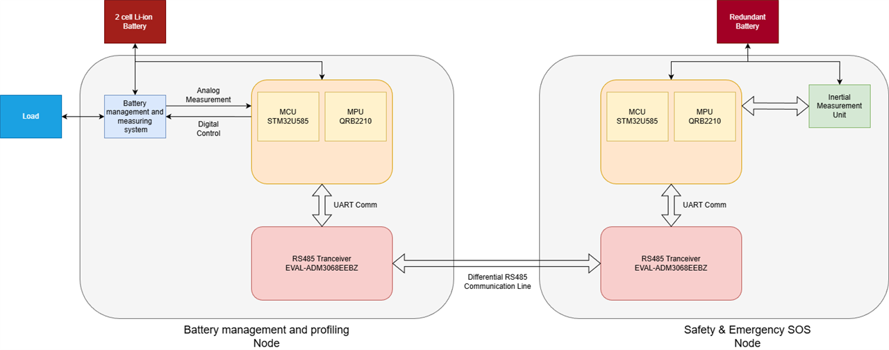
Figure 1: High level block diagram
1. Battery Management & Profiling Node
The first part of EVA Guardian is responsible for understanding what is happening inside the battery system.The prototype uses a 2S 18650 Li-ion battery configuration, together with an HX-2S-A2 battery protection board.The HX-2S-A2 provides the basic battery protection layer, while the Arduino UNO Q sits above it as the intelligent monitoring and analytics layer.This distinction is important.The protection hardware is responsible for fundamental battery safety, while my software will focus on understanding the battery's behaviour.
The battery node therefore brings together:
- 2S 18650 battery pack
- HX-2S-A2 BMS
- ACS723 current sensor
- LF412-based voltage measurement circuit
- NTC temperature sensing
- 2S Li-ion charger
- L298N-controlled load
- Relay-based switching
- Arduino UNO Q
- ADM3068E RS485 interface
Each component has a specific role in creating the battery intelligence system.
2. Understanding Battery Current
One of the most important parameters in the battery system is current.I am using the ACS723 current sensor to measure the current flowing through the battery/load system.This allows the Arduino UNO Q to understand how heavily the battery is being loaded and how the current changes during different operating conditions.Together with battery voltage, current also allows me to calculate power and energy consumption.
This provides the foundation for monitoring parameters such as:
- Battery power
- Charging power
- Discharging power
- Energy consumption
- Peak current
- Load behaviour
- Charging and discharging efficiency
Instead of looking at battery voltage alone, the system can therefore start building a much more complete picture of how the battery is actually being used.
3. Battery Voltage and Temperature
Current is only one part of the story.The battery voltage is measured through the LF412-based analogue signal conditioning circuit, allowing the voltage to be safely acquired by the Arduino UNO Q's ADC.The system will continuously monitor the battery voltage during both charging and discharging.Temperature is another critical parameter.An NTC thermistor is used to monitor the battery temperature, particularly during high-current operation and charging.This becomes useful when multiple parameters are considered together.For example, a high current by itself may be completely normal.But if the system observes:
High current + rapid temperature rise + unusual voltage behaviour
then the event becomes much more interesting from a battery-health perspective.This combination of electrical and thermal information is what will eventually allow me to explore more advanced battery analytics and machine learning.
4. Creating Controlled Battery Conditions
To understand the battery properly, I need to expose it to different operating conditions.This is where the L298N motor driver and load become useful.The load can be controlled to create different discharge conditions, while the Arduino UNO Q monitors the resulting battery behaviour.By changing the load, I can generate different current profiles and observe how the battery responds.The 2S charger provides the corresponding charging side of the experiment.
This gives me a controlled environment in which I can study:
- Charging behaviour
- Discharging behaviour
- Different load conditions
- Current variations
- Voltage response
- Temperature response
- Energy consumption
These measurements will eventually become the foundation for battery profiling and ML-based analysis.
5. The Arduino UNO Q – Intelligence Layer
The Arduino UNO Q is at the heart of the battery node.Its role is much more than simply reading sensor values.
It will acquire and process:
- Battery voltage
- Battery current
- Battery temperature
- Charging/discharging status
- Load condition
From this information, the system can build higher-level battery information such as:
- State of Charge
- Power
- Energy consumption
- Efficiency
- Battery operating history
- Abnormal operating conditions
As the project progresses, I also plan to use the collected battery data to investigate machine-learning-based State of Health estimation, anomaly detection and predictive maintenance.This is where the project moves from traditional battery monitoring toward the intelligent battery concept introduced in my previous post.
6. Incident Detection & Safety Node
The second half of EVA Guardian focuses on something equally important:
What happens when the vehicle itself behaves unexpectedly?
For this, I am using a second Arduino UNO Q together with the GY-91 sensor module.The GY-91 provides an MPU6500 accelerometer and gyroscope, along with the BMP280 pressure and temperature sensor.For the initial implementation, the MPU6500 is the primary sensor for vehicle motion analysis.
The system will use the IMU data to investigate events such as:
- Abrupt acceleration
- Harsh braking
- Sudden impacts
- Excessive vibration
- Potholes
- Speed breakers
- Sharp turns
- Sudden stops
- Vehicle tip-over
- Potential accident scenarios
The goal is not simply to trigger an alarm whenever acceleration crosses a fixed threshold.Real-world vehicle motion is much more complicated than that.A speed breaker, pothole and accident can all create large acceleration peaks.Therefore, the challenge is to teach the system to distinguish between these different events.This is where the machine-learning aspect of the safety node becomes important.
7. From IMU Data to Incident Detection
The incident detection node will initially collect the accelerometer and gyroscope data from the GY-91.The data can then be stored and labelled according to different vehicle conditions.
For example:
- Normal movement
- Acceleration
- Braking
- Harsh braking
- Turning
- Pothole
- Speed breaker
- Sudden impact
- Tip-over
This dataset can then be used to train an ML model.My planned approach is to collect the data using the Arduino UNO Q, generate the dataset, train and validate the model using EdgeImpulse, and deploy it back onto the Arduino UNO Q.The eventual objective is to perform the inference locally at the edge.This means the vehicle does not have to continuously depend on a cloud service just to determine whether an abnormal motion event has occurred.
8. Why a Second Battery?
The safety node also has its own 2S 18650 battery and HX-2S-A2 protection system.This is an important part of the overall safety philosophy.In a conventional vehicle architecture, the primary battery is responsible for powering almost everything.But consider a situation where the primary battery or its power path becomes unavailable following an accident.If the safety system also depends entirely on that same battery, the vehicle could lose its ability to communicate exactly when communication becomes most important.EVA Guardian therefore explores a separate battery-backed power path for the safety node.
The objective isn't to keep the vehicle running.Instead, the backup source is intended to support essential functions such as:
- Safety monitoring
- Emergency communication
- SOS operation
- Basic diagnostics
The philosophy is simple:
If the vehicle cannot continue moving, the safety system should still be able to communicate.
9. Automatic Power Switching
The second node includes an automatic power switching relay arrangement.Under normal conditions, the safety system can operate from its primary power source.If that source becomes unavailable, the switching circuit can transfer the system to the redundant battery.This provides an additional layer of resilience to the safety system.The important point here is that the redundant battery isn't intended to be another traction battery.It is an emergency energy reserve for the electronics that need to remain alive when everything else has stopped.
10. Communication Between the Two Nodes
The two systems need to communicate because battery condition and vehicle safety cannot always be considered independently.For this purpose, I am using Analog Devices ADM3068E RS485 transceiver evaluation boards.
The Battery Management Node can share information such as:
- Battery voltage
- Battery current
- Battery temperature
- State of Charge
- State of Health
- Power
- Energy consumption
- Battery warnings
- Battery anomaly status
The Safety Node can provide:
- Motion state
- Acceleration information
- Gyroscope information
- Incident classification
- Incident confidence
- Emergency status
The RS485 connection therefore acts as the communication backbone between the two intelligent nodes.
11. Why RS485?
The choice of RS485 is also intentional.The objective of EVA Guardian is not just to create a demonstration where two boards exchange data.I want to explore an architecture that can eventually be extended into a distributed EV monitoring system.RS485 provides a robust differential communication interface and gives the architecture room for future expansion.
For example, additional nodes could eventually be introduced for:
- Motor monitoring
- Thermal monitoring
- Charging system monitoring
- Additional battery packs
- Environmental sensing
- Other vehicle diagnostics
This modular approach makes it easier to expand the system without redesigning the entire architecture.
12. Bringing Everything Together
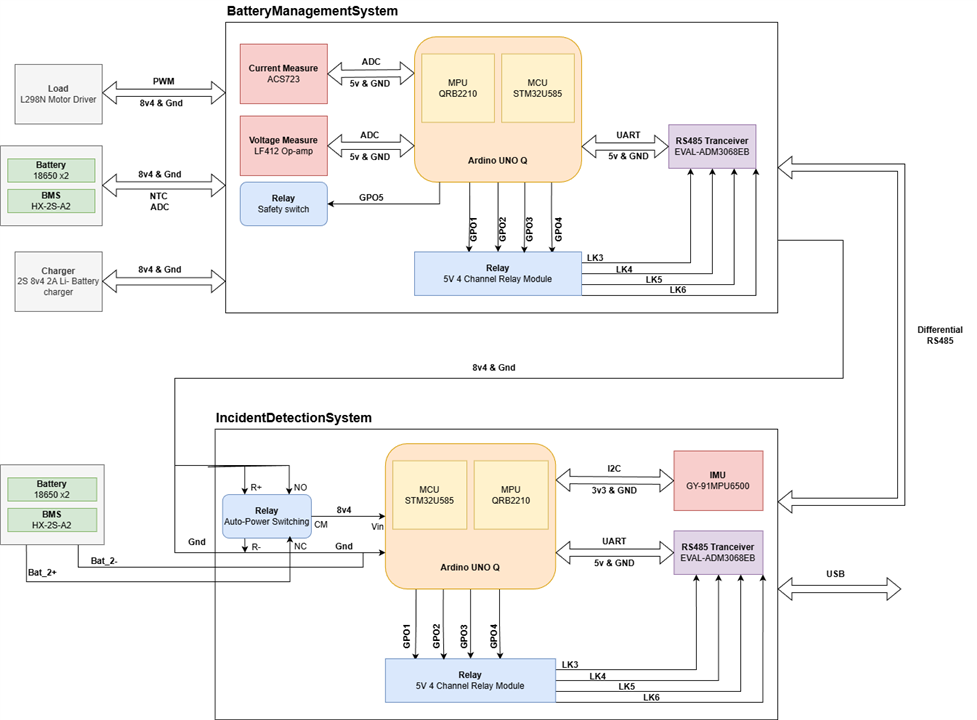
Figure 2: Technical Architecture
This is where the two nodes become a single system.During normal operation, the Battery Management Node continuously monitors the battery.The voltage, current and temperature sensors provide the raw information required to understand the battery's electrical and thermal behaviour.The Arduino UNO Q processes this information and gradually builds a battery profile.At the same time, the Safety Node continuously monitors vehicle movement through the GY-91.The two systems communicate over RS485, allowing the master node to maintain an overall view of the vehicle.The master node can therefore receive information about:
- Battery condition
- Battery health
- Battery energy consumption
- Temperature
- Vehicle motion
- Incident status
- System faults
If the battery begins behaving abnormally, the battery node can raise a warning.If the vehicle experiences an unusual motion event, the safety node can classify it.The master node can then combine the information from both systems before moving into the emergency response process.
13. From Detection to Emergency Response
One of the most important design decisions is that the ML model should not directly trigger an SOS message.Suppose the ML model identifies a potential accident.That event should first pass through an additional verification layer.
The system can consider factors such as:
- Impact magnitude
- Duration of the event
- Vehicle movement after the event
- Vehicle orientation
- Repeated abnormal motion
- ML confidence
- Battery/system condition
This helps differentiate a genuine emergency from events such as a pothole or speed breaker.Once the event has been sufficiently verified, the master node can initiate the emergency workflow.The redundant battery system can ensure that the safety electronics continue operating even if the primary power source has failed.The ultimate objective is to allow the system to communicate an emergency event and location through a consumer smartphone, without requiring a dedicated cellular modem as part of the prototype.
14. How the System Will Evolve
The architecture has been designed so that the project can be developed in stages.Initially, I will focus on making the basic battery monitoring system reliable.Once voltage, current and temperature measurements are working correctly, I can start collecting battery behaviour data.That data will then be used for battery profiling and eventually ML-based analysis.In parallel, the incident detection node will begin with raw IMU acquisition.After sufficient data has been collected, I can start developing and validating the incident classification model.Finally, both systems will be brought together through RS485 and integrated with the LabVIEW interface and emergency workflow.This incremental approach is important because it ensures that each part of the system is understood and validated before moving to the next stage.
Bringing the Vision from Part I to Reality
In my first post, I discussed the problem I wanted EVA Guardian to address.The problem wasn't simply battery monitoring.It was about making an EV more aware, reliable and resilient.With this architecture, I am now starting to translate that idea into actual hardware.
The Battery Management Node focuses on one question:
"How healthy is the energy system, and is it behaving as expected?"
The Safety Node focuses on another:
"What is happening to the vehicle, and is the situation becoming dangerous?"
And the communication and emergency architecture brings these two perspectives together.The result is intended to be more than a collection of sensors.It is an attempt to build an intelligent safety ecosystem where the system can sense → understand → decide → respond.Here are my github repo and youtube explanatroy video for the better understanding
Github Repo: https://github.com/ForgedCircuits/EVA-Guardian.git
Youtube: The Technical Architecture of EV Guardian
